AES-100 ADSL-Ethernet Switch August 2001 User’s Guide
AES-100 User’s Guide Copyright Copyright © 2001 by ZyXEL Communications Corporation. The contents of this publication may not be reproduced in any part or as a whole, transcribed, stored in a retrieval system, translated into any language, or transmitted in any form or by any means, electronic, mechanical, magnetic, optical, chemical, photocopying, manual, or otherwise, without the prior written permission of ZyXEL Communications Corporation. Published by ZyXEL Communications Corporation.
AES-100 User’s Guide ZyXEL Limited Warranty ZyXEL warrants to the original end user (purchaser) that this product is free from any defects in materials or workmanship for a period of up to two (2) years from the date of purchase.
AES-100 User’s Guide Interference Statements and Warnings FCC Interference Statement: This device complies with Part 15 of the FCC rules. Operation is subject to the following two conditions: (1) This device may not cause harmful interference. (2) This device must accept any interference received, including interference that may cause undesired operations. FCC Warning! This equipment has been tested and found to comply with the limits for a Class A digital device, pursuant to Part 15 of the FCC Rules.
AES-100 User’s Guide Customer Support If you have questions about your ZyXEL product or desire assistance, contact ZyXEL Communications Corporation offices worldwide, in one of the following ways: Contacting Customer Support When you contact your customer support representative, have the following information ready: ♦ Product model and serial number. ♦ Firmware version information. ♦ Warranty information. ♦ Date you received your product.
AES-100 User’s Guide Table of Contents Copyright .............................................................................................................................................................................................................ii ZyXEL Limited Warranty.................................................................................................................................................................................iii Interference Statements and Warnings ..............
AES-100 User’s Guide 3.4.1 Uptime Command....................................................................................................................... 3-2 3.4.2 Version Command ...................................................................................................................... 3-2 3.4.3 Restart Command........................................................................................................................ 3-3 3.4.4 Passwd Command ...................................
AES-100 User’s Guide 5.3.2 Status Command..........................................................................................................................5-1 Chapter 6 Bridge Configuration............................................................................................................................................................ 6-1 6.1 Bridge Port Numbers ...........................................................................................................................
AES-100 User’s Guide 8.4.2 Trap Add Command.................................................................................................................... 8-5 8.4.3 Trap Delete Command................................................................................................................. 8-5 8.4.4 Trap Flush Command.................................................................................................................. 8-5 8.4.5 Trap List Command ......................................
AES-100 User’s Guide List of Figures Figure 1-1 MTU Application..........................................................................................................................................................................1-3 Figure 1-2 ISP Application.............................................................................................................................................................................1-4 Figure 2-1 AES-100 Front Panel ........................................
AES-100 User’s Guide Table 11-8 Troubleshooting the SNMP Server .........................................................................................................................................11-3 Table 11-9 Troubleshooting Telnet..............................................................................................................................................................
AES-100 User’s Guide Preface Congratulations on your purchase of the AES-100 ADSL-Ethernet Switch. This preface introduces you to the AES-100 and discusses the organization and conventions of this user’s guide. It also provides information on other related documentation. About the AES-100 The AES-100 is an ADSL (Asymmetrical Digital Subscriber Line) to Ethernet switch. It allows you to multiplex traffic from up to 16 ADSL lines to an Ethernet network before it is forwarded to the Internet.
AES-100 User’s Guide Chapter 1 Getting to Know the AES-100 This chapter describes the key features, benefits and applications of your AES-100. The AES-100 is an ADSL (Asymme trical Digital Subscriber Line) to Ethernet switch. It aggregates traffic from up to 16 ADSL lines to Ethernet. ADSL allows the coexistence of broadband data service and conventional voice service over the same telephone wire. When deployed together with ZyXEL’s ADSL modems, e.g., P642M, and WAN routers, e.g.
AES-100 User’s Guide • Up to 4096 MAC entries address table Protocol • Multiple Protocols over AAL5 (RFC 1483) Management • Remote configuration backup/restore and firmware upgrade • SNMP manageable • Text-based management locally via console port and remotely via telnet • TFTP (Trivial File Transfer Protocol) for transferring firmware and configuration files Security 1-2 • Password protection for system management • Port-based VLAN Getting to Know the AES-100
AES-100 User’s Guide 1.2 Benefits 1.2.1 MTU Application The following diagram depicts a typical application of the AES-100 is in a large residential building, or multiple tenant unit (MTU), that leverages the existing phone line wiring to provide Internet access to all tenants. A tenant connects a computer to the phone line in a unit using an ADSL modem. The other end of the phone line is connected to a port on the AES-100.
AES-100 User’s Guide 1.2.2 ISP Application The AES-100 can also be used by an Internet Service Provider (ISP) as an IP DSLAM. The AES-100 terminates all of the ADSL ATM circuits and converts the traffic to IP packets. All IP traffic goes directly to the ISP’s internal Ethernet network, before being routed to the Internet. Figure 1-2 ISP Application 1.2.3 Compact Design for Limited Space The AES-100 occupies only 1.5 U of standard Telco rack space.
AES-100 User’s Guide • Each network module has eight RJ-11 ports to the CO side and eight RJ-11 ports to the USER side • Each network module has one 10 M Ethernet port • Each network module has one RS-232 console port for local configuration and management Dimensions • In mm: 440 (W) x 320 (L) x 66 (H) Weight • 6.
AES-100 User’s Guide Chapter 2 Hardware Overview This chapter gives a brief introduction to the AES-100 hardware. 2.1 Unpacking the AES-100 Before installing, check to see that all the components of the AES-100 are included in the package. 2.
AES-100 User’s Guide Figure 2-1 AES-100 Front Panel 2.3.1 Front Panel Ports The following table describes the ports on the front panel of an AES-100 network module. Table 2-1 Front Panel Ports of an ADSL Network Module PORTS DESCRIPTION LAN The LAN port is a 10 Mbps Ethernet port for connection to a router. CONSOLE The CONSOLE port is an RS-232 port for configuring the AES-100. USER 1-8 The USER port connects to the user (subscriber) ADSL equipment.
AES-100 User’s Guide of your computer. You can use an extension RS -232 cable if the enclosed one is too short. After the initial setup, you can modify the configuration remotely through telnet connections. 2.5 ADSL Port Connections The line from the user carries both the ADSL and the voice signals.
AES-100 User’s Guide Connect the female end of the power cord to the power receptacle on the rear panel of your AES-100 (just to the right of the warning sticker) as seen next. Connect the other end of the cord to a power outlet. Make sure that no objects obstruct the airflow of the fans (located on the side of the unit).
AES-100 User’s Guide Chapter 3 Software Configuration This section describes the general software configuration of the AES-100 through the command line interface. 3.1 Command Line Interface The AES-100 uses text command lines as the user interface for software configuration. Before discussing the details of configuration, the rules of the commands are listed below. 1. The command keywords are in regular courier font. 2. The command keywords must be entered exactly as shown, i.e.
AES-100 User’s Guide 3.3 Command Structure The system uses a two-level command structure. The commands related to one subsystem are grouped under a primary command of that subsystem, e.g., to configure the ADSL parameters, you must first ente r the ADSL subsystem by entering the adsl command. When you are in a subsystem, the system reminds you by including the subsystem name in the command prompt, e.g., 192.168.1.1 adsl > To get back to the top level prompt from a subsystem, use the home command. 3.3.
AES-100 User’s Guide 3.4.3 Restart Command Syntax: restart The restart command instructs the system to perform a warm start, i.e., restarting the system without turning the power on and off. It is very important that you remember your password. If you forget it, refer to the Troubleshooting section for help. 3.4.4 Passwd Command Syntax: passwd The passwd command changes the management password. The management password is used for authentication at console or telnet login.
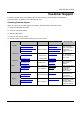
AES-100 User’s Guide Chapter 4 ADSL Configuration The ADSL (Asymmetrical Digital Subscriber Line) subsystem allows you to configure and monitor the ADSL ports. 4.1 ADSL Standards The AES-100 supports both the G.lite and the G.dmt standards. G.lite is intended to minimize the cost for the consumer market. Table 4-1 ADSL Standards STANDARD MAXIMUM DOWNSTREAM MAXIMUM UPSTREAM G.dmt 8160 Kbps 1024 Kbps G.lite 1536 Kbps 512 Kbps 4.2 Configured Vs.
AES-100 User’s Guide - Enable/Disable State: disabled - Maximum upstream speed: 512 Kbps - Maximum downstream speed: 2048 Kbps - Operational mode: auto 4.4 ADSL Commands 4.4.1 Config Save Command Syntax: config save The config save command saves the ADSL configuration into nonvolatile memory. 4.4.2 Disable Port Command Syntax: disable port where = port number, from 1 to 8 The disable port command forcibly disables the specified ADSL port.
AES-100 User’s Guide 4.4.4 Enable Port Command Syntax: enable port where = port number, from 1 to 8 The enable port command forcibly enables the specified ADSL port. The factory default of all ports is disabled. A port must be enabled before data transmission can occur. An enabled but disconnected ADSL port generates more heat than an operating port. To minimize heat generation and to enhance reliability, remember to disable a port when it is not in use. 4.4.
AES-100 User’s Guide tone 128-159: 44 44 44 34 44 34 43 44 33 43 34 33 33 33 33 34 tone 160-191: 43 33 33 34 34 33 23 33 33 33 22 33 33 33 33 33 tone 192-223: 33 33 33 23 22 33 33 33 23 33 33 33 22 23 22 32 tone 224-255: 22 22 22 22 20 22 22 22 20 0 0 0 0 0 0 0 US carrier load: number of bits per symbol(tone) tone 0- 31: 0 0 0 0 2 34 55 77 88 89 99 99 99 98 88 87 tone 32- 63: 0 0 0 0 0 0 0 0 0 0 0 0 0 0 0 0 The results can determine whether a given sub-carrier loop has suffi
AES-100 User’s Guide Total Transceiver Output Power : 8dB Current ATUR Information: Country code 0 Provider Code 01020304 Capabilities: g.dmt POTS overlap (Annex A) The results contain the operating modes, interleave delay, parity byte assignment, parity bytes per codeword, symbols per codeword and interleave depth.
AES-100 User’s Guide fe_loss_seconds/ne_loss_seconds : 0/0 fe_fec_seconds/ne_fec_seconds : 0/0 fast_trains : 0 fast_trains_fail : 0 These counts contain line performance data that has been accumulated since the system started. In the list above the definitions of near end/far end will always be relative to the ATU-C. Downstream (ds) refers to data from the ATU-C and upstream (us) refers to data from the ATU-R. 4.4.
AES-100 User’s Guide list port where = port number, from 1 to 8 The list port command shows the configured maximum upstream/downstream speeds, the mode (or standard), and enable/disable state of an individual ADSL port. 4.4.11 List Ports Command Syntax: list ports The list ports command shows the configured maximum speeds, modes and states of all ADSL ports. 4.4.
AES-100 User’s Guide = Maximum ADSL upstream speed in Kbps. = Maximum ADSL downstream speed in Kbps. = Operational mode; the available choices are glite, gdmt or auto. The set ports command sets the same maximum upstream/downstream speeds and the mode, or standard, for all ADSL ports. Note that the upstream speed must be less than or equal to the downstream speed. The mode parameter specifies the standard that the ports are allowed.
AES-100 User’s Guide Chapter 5 10 Mbps Ethernet Port Configuration The Ethernet subsystem allows you to configure and monitor the 10 Mbps Ethernet port. 5.1 10 Mbps Ethernet The AES-100 supports 10 Mbps Ethernet. In a 10 Mbps Ethernet, the duplex mode can be half duplex or full duplex. The Ethernet port uses the pre-configured duplex mode setting when making a connection, thus requiring you to check the setting of the peer Ethernet port in order to connect. 5.
AES-100 User’s Guide 5-2 10 Mbps Ethernet Port Configuration
AES-100 User’s Guide Chapter 6 Bridge Configuration The bridge subsystem allows you to configure and monitor the bridging and port-based VLAN functions of the AES-100. The AES-100 supports IEEE 802.1d transparent bridging; but not the static filtering feature or spanning tree protocol. The bridge learns the source MAC addresses of sender hosts by inspecting incoming Ethernet frames and recording the learned MAC addresses with their incoming port numbers into its filtering database.
AES-100 User’s Guide - Bridge port 9 (ADSL port 8) allowed to bridge port 1 (Ethernet port) only It is recommended that you do not alter these settings, or the AES-100 may not work correctly. The default VLAN settings allow each ADSL port to communicate back and forth with only the Ethernet port, and not with other ADSL ports. The following figure illustrates this. Figure 6-1 Default VLAN Settings 6.3 Bridge Commands 6.3.
AES-100 User’s Guide The filterage command sets or shows the aging out timer period of the filtering database. It is recommended that you use the default setting. If the time interval is reduced to a setting that is too short, it could increase broadcast traffic and reduce the available bandwidth. 6.3.4 Flush Command Syntax: flush [port] where [port] = bridge port number, from 1 to 9 The flush command flushes out the filtering database of the specified bridge port.
AES-100 User’s Guide The portfilter command sets or displays the port-based VLAN configuration. An example is shown next. 192.168.1.1 > bridge 192.168.1.
AES-100 User’s Guide The following figures illustrate the above example. Notice that ports 2 (ADSL port 1) and 3 (ADSL port 2) are able to communicate with each other, as well as with the Ethernet. All of the other ports will only be able to communicate with the Ethernet port. This first figure illustrates the first command line. Port 1 (the Ethernet port) is linked to all 8 ADSL ports. Figure 6-2 Example of Modified VLAN Port 1 The following figure illustrates the second command line.
AES-100 User’s Guide Figure 6-4 Example of Modified VLAN Port 3 This figure illustrates the fact that port 1 (the Ethernet port) is linked to ports 2 (ADSL port 1) and 3 (ADSL port 2). Ports 2 (ADSL port1) and 3 (ADSL port 2) are also linked to each other.
AES-100 User’s Guide Chapter 7 IP Configuration This chapter shows you how to configure the IP (Internet Protocol) parameters. The IP host implementation in the AES-100 allows you to manage it over the network. More often than not, you have more than one AES-100 for a particular installation. Before you start configuring the AES-100s, make sure that you 1. Plan ahead. 2. Have a complete diagram showing the whole network. 3. Record the IP parameters assigned to the equipment in your network. 7.
AES-100 User’s Guide Line 7 tells the system to restart, in order to make the IP address configuration take effect. The AES-100 does not need to be restarted after configuration of other items. For example, if you want the AES-100 to have 172.21.100.1 as the IP address, 255.255.255.0 for the subnet mask and 172.21.100.254 for the default gateway, you may use the following command sequence: 192.168.1.1> ip 192.168.1.1 ip> device delete ether 192.168.1.1 ip> device add ether ether //bridge 172.21.100.1 192.
AES-100 User’s Guide 7.2.2 Ping Command Syntax: ping [ []] This is an IP facility to check for network functionality by sending an echo request to another IP host and waiting for the reply. The host parameter specifies the IP address of the target. The optional ttl (time to live) limits the number of hops (routers) that the echo request can travel before it reaches the target. The size parameter specifies the size of the payload, i.e.
AES-100 User’s Guide Chapter 8 Remote Management This chapter shows you how to manage the AES-100 remotely. More often than not, you will have the AES-100 located remotely making its remote management very useful. 8.1 Management by Telnet After you have set up the IP parameters and connected the AES-100 to the network, you can manage it remotely with telnet. You can use any telnet client that you find convenient.
AES-100 User’s Guide Figure 8-1 SNMP Management Model An SNMP managed network consists of two main component types: agents and a manager. An agent is a management software module that resides in a managed device (the AES-100). An agent translates the local management information from the managed device into a form compatible with SNMP. The manager is the station through which network administrators perform network management functions. It executes operations that control and monitor the managed devices.
AES-100 User’s Guide access [] where = Specifies read-only/read-write permission. = Password needed to access the SNMP agent on the AES-100. [] = Optional IP address of the allowed SNMP manager. This command allows read-only or read-write access. If the IP address is specified, access is allowed for the manager station with that address only. 8.3.
AES-100 User’s Guide ♦ coldStart Trap (defined in RFC-1215) : This trap is sent at system start-up. ♦ authenticationFailure Trap (defined in RFC-1215) : This trap is sent if a request arrives with an invalid community string. ♦ linkUp Trap (defined in RFC-1215) : This trap is sent when an ADSL port is up. ♦ linkDown Trap (defined in RFC-1215) : This trap is sent when an ADSL port is down.
AES-100 User’s Guide 8.4.2 Trap Add Command Syntax: trap add [] where = The password used by the AES-100 to authenticate itself to the trap server. = The IP address of the trap server. [] = The optional port parameter is for specifying the UDP port number on the server in case it is different from the default of port 162. This command adds a trap server. 8.4.
AES-100 User’s Guide Chapter 9 Configuration Backup/Restore This chapter describes the process for backing up your user settings (configuration) from the AES-100 onto your computer and how to restore them to the AES-100. The AES-100 uses TFTP for configuration backup/restore through its built -in TFTP server. You can use any TFTP client to connect to the AES-100. Do not turn off the AES-100 during the updating process, as it may corrupt the firmware and make your AES-100 unusable. 9.
AES-100 User’s Guide 9.3 Configuration Backup You can backup all or some configuration files from the AES-100 to your computer. For example, to backup the configuration of ADSL ports and IP settings, the procedure on your computer is as follows: Step 1. Connect to the AES-100 with your favorite TFTP client. The command is generally tftp at the computer command prompt. Step 2. Set the binary mode. tftp> binary Step 3.
AES-100 User’s Guide tftp> put initadsl tftp> put resolve tftp> put tftpupdt.end where tftplock.key = The file that contains the SNMP write community string (password). tftpupdt.beg = An empty file (with no content). Marks the beginning of the restore process, used only in restoration. initadsl = The configuration file for ADSL ports. resolve = The configuration file for IP parameters. tftpupdt.end = An empty file (with no content). Marks the end of the restore process, used only in restoration.
AES-100 User’s Guide Chapter 10 Firmware Upload ZyXEL periodically releases new firmware for the AES-100 for bug fixes and enhancements. Please check the web site at www.zyxel.com every now and then for the latest firmware release. The AES-100 has two ways to update firmware; one is done through BOOTP/TFTP and the other uses TFTP.
AES-100 User’s Guide Step 2. Connect your AES-100’s console port to a computer’s serial port with an RS-232 cable. Step 3. Run any terminal emulation program, e.g., Windows’ built-in HyperTerminal, with the following parameters: - VT100 terminal emulation - 9600 bps - No parity, 8 data bits, 1 stop bit - No flow control Step 4. Run BootpTftp.exe, to bring up the following window.
AES-100 User’s Guide Step 5. Click the New button to create a MAC address entry. The Input Box window will pop up as shown next. Step 6. Input the MAC address of the AES-100 and then click OK. You can find the MAC address of the AES- 100 on its boot console. Figure 10-2 Input MAC Step 7. Set up the host address (the IP address you want to assign to the AES -100), server address (the IP address of this computer), net mask, gateway and filename (the new firmware name). Click Update Database .
AES-100 User’s Guide Figure 10-3 Database Edit Dialog Step 8. Choose Normal Bootp to enable normal BOOTP/TFTP functions. Figure 10-4 Enable BOOTP/TFTP Step 9. Restart the AES-100 and press any key within three seconds to get the following console window: SDRAM Testing . . . AES-100 Boot Loader, Feb 7 2001 12:06:03 Copyright © 2001 ZyXEL Communications Corp. Mac address 00:A0:C5:12:34:56 Figure 10-5 Enter Debug Mode Step 10. Enter atnb at the AES-100 boot console. Step 11.
AES-100 User’s Guide 10.2 TFTP Firmware Update on the AES-100 The AES-100 uses TFTP for firmware updates through its built-in TFTP server when the AES-100 is operational. To update the firmware, first download it from the ZyXEL web site and store it on your computer. You can use any TFTP client to connect to the AES-100. The procedure for TFTP update is similar to the procedure for restoring configuration.
AES-100 User’s Guide Chapter 11 Troubleshooting This chapter covers potential problems and possible remedies. After each problem description, some steps are provided to help you diagnose and solve the problem. 11.1 ADSL LED(s) An ADSL LED is not on. Table 11-1 Troubleshooting the ADSL LED(s) STEPS 1 CORRECTIVE ACTION Unplug the phone wire coming from the USER port of the AES-100 and connect the user’s ADSL modem or router directly to the USER port of the AES-100 using a different telephone wire.
AES-100 User’s Guide 11.3 ADSL LED(s) turn On and Off An ADSL LED turns on and off intermittently. Table 11-3 Troubleshooting a Non-Constant ADSL LED STEPS 1 CORRECTIVE ACTION Unplug the phone wire coming from the USER port of the AES-100 and connect the user’s ADSL modem or router directly to the USER port of the AES-100 using a different telephone wire. If the ADSL LED stays on, check for a problem with the building’s phone wire.
AES-100 User’s Guide 11.6 Password I forgot the password to my AES-100. Table 11-6 Troubleshooting the Password OPTIONS CORRECTIVE ACTION 1 Send a screen shot of your AES-100’s MAC address to your local distributor. 2 Refer to the BOOTP/TFTP Firmware Update section to update your firmware. All settings will return to default value, so any configurations you have made will be lost. 11.7 Remote Server The user’s computer behind the ADSL modem or router can not access a remote server.
AES-100 User’s Guide 11.9 Telnet I can not telnet into the AES-100. Table 11-9 Troubleshooting Telnet STEPS CORRECTIVE ACTION 1 Make sure that a telnet session is not already operating. The AES-100 will only accept one telnet session at a time. 2 Ping the AES-100 from your computer. If you are able to ping the AES-100 but are still unable to telnet, contact the distributor. If you cannot ping the AES-100, check the IP addresses in the AES-100 and your computer.
AES-100 User’s Guide Index A Connections AC INPUT ............................................................................... 2-4 ADSL Port ...........................................................................2-3 Access Flush Command........................................................ 8-3 Contacting Customer Support .................................................v Access List Command ...........................................................8-3 Copyright ............................
AES-100 User’s Guide General IP Commands..........................7-2, 9-1, 9-2, 10-1, 10-5 P GetNext .............................................................................8-2, 8-3 parity byte assignment ...........................................................4-4 glite ....................................................................................4-6, 4-7 parity bytes per codeword..................................................... 4-4 H Help Facility...................................
AES-100 User’s Guide Statistics Command ............................................................... 7-2 upstream (us) ...........................................................................4-5 Syntax Conventions ..................................................................xi Uptime Command ..................................................................3-2 System Commands................................................................. 3-2 USER port ......................................