ES-2108 Series Ethernet Switch User’s Guide Version 3.
ES-2108 Series User’s Guide Copyright Copyright © 2006 by ZyXEL Communications Corporation. The contents of this publication may not be reproduced in any part or as a whole, transcribed, stored in a retrieval system, translated into any language, or transmitted in any form or by any means, electronic, mechanical, magnetic, optical, chemical, photocopying, manual, or otherwise, without the prior written permission of ZyXEL Communications Corporation. Published by ZyXEL Communications Corporation.
ES-2108 Series User’s Guide Interference Statements and Warnings FCC Statement This switch complies with Part 15 of the FCC rules. Operation is subject to the following two conditions: 1 This switch may not cause harmful interference. 2 This switch must accept any interference received, including interference that may cause undesired operations. FCC Warning This equipment has been tested and found to comply with the limits for a Class A digital switch, pursuant to Part 15 of the FCC Rules.
ES-2108 Series User’s Guide Certifications 1 Go to www.zyxel.com 2 Select your product from the drop-down list box on the ZyXEL home page to go to that product's page. 3 Select the certification you wish to view from this page. Safety Warnings For your safety, be sure to read and follow all warning notices and instructions. • To reduce the risk of fire, use only No. 26 AWG (American Wire Gauge) or larger telecommunication line cord. • Do NOT open the device or unit.
ES-2108 Series User’s Guide ZyXEL Limited Warranty ZyXEL warrants to the original end user (purchaser) that this product is free from any defects in materials or workmanship for a period of up to two years from the date of purchase.
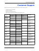
ES-2108 Series User’s Guide Customer Support Please have the following information ready when you contact customer support. • • • • Product model and serial number. Warranty Information. Date that you received your device. Brief description of the problem and the steps you took to solve it. METHOD SUPPORT E-MAIL TELEPHONE* WEB SITE FAX FTP SITE REGULAR MAIL LOCATION CORPORATE HEADQUARTERS (WORLDWIDE) CZECH REPUBLIC DENMARK FINLAND SALES E-MAIL support@zyxel.com.tw +886-3-578-3942 sales@zyxel.
ES-2108 Series User’s Guide METHOD SUPPORT E-MAIL TELEPHONE* WEB SITE SALES E-MAIL FAX FTP SITE info@pl.zyxel.com +48-22-5286603 www.pl.zyxel.com ZyXEL Communications ul.Emilli Plater 53 00-113 Warszawa Poland www.zyxel.ru ZyXEL Russia Ostrovityanova 37a Str. Moscow, 117279 Russia www.zyxel.es ZyXEL Communications Alejandro Villegas 33 1º, 28043 Madrid Spain www.zyxel.se ZyXEL Communications A/S Sjöporten 4, 41764 Göteborg Sweden www.ua.zyxel.com ZyXEL Ukraine 13, Pimonenko Str.
ES-2108 Series User’s Guide Table of Contents Copyright .................................................................................................................. 3 Interference Statements and Warnings.................................................................. 4 ZyXEL Limited Warranty ......................................................................................... 6 Customer Support ...................................................................................................
ES-2108 Series User’s Guide Chapter 3 Hardware Overview................................................................................................ 37 3.1 Front Panel Connection .................................................................................... 37 3.1.1 Console Port ........................................................................................... 38 3.1.2 Ethernet Ports .......................................................................................... 38 3.1.2.
ES-2108 Series User’s Guide 7.3 General Setup .............................................................................................. 63 7.4 Introduction to VLANs ...................................................................................... 65 7.5 IGMP Snooping ................................................................................................ 66 7.6 Switch Setup Screen 7.7 IP Setup ...................................................................................... 66 ...
ES-2108 Series User’s Guide Chapter 12 Bandwidth Control................................................................................................. 93 12.1 Bandwidth Control Setup ................................................................................ 93 Chapter 13 Broadcast Storm Control ...................................................................................... 95 13.1 Overview .....................................................................................................
ES-2108 Series User’s Guide Chapter 19 Static Route ...........................................................................................................111 19.1 Configuring Static Route ...............................................................................111 Chapter 20 Differentiated Services .........................................................................................113 20.1 Overview ............................................................................................
ES-2108 Series User’s Guide 22.9 HTTPS Example ............................................................................................ 131 22.9.1 Internet Explorer Warning Messages ................................................... 131 22.9.2 Netscape Navigator Warning Messages .............................................. 132 22.9.3 The Main Screen .................................................................................. 133 22.10 Service Port Access Control 22.11 Remote Management .......
ES-2108 Series User’s Guide 27.5.1 List of Available Commands ................................................................. 152 27.5.2 Detailed Command Information ........................................................... 153 27.6 Command Modes .......................................................................................... 154 27.7 Using Command History ................................................................................ 155 27.8 Saving Your Configuration .......................
ES-2108 Series User’s Guide 28.10.7 egress set .......................................................................................... 184 28.10.8 qos priority .......................................................................................... 185 28.10.9 name .................................................................................................. 185 28.10.10 speed-duplex .................................................................................... 186 Chapter 29 IEEE 802.
ES-2108 Series User’s Guide Product Specifications ........................................................................................ 207 Appendix B IP Subnetting.........................................................................................................211 Index......................................................................................................................
ES-2108 Series User’s Guide 18 Table of Contents
ES-2108 Series User’s Guide List of Figures Figure 1 Backbone Application .............................................................................. 30 Figure 2 Bridging Application ................................................................................ 30 Figure 3 High Performance Switched Application ................................................. 31 Figure 4 Tag-based VLAN Application ...................................................................
ES-2108 Series User’s Guide Figure 39 Static MAC Forwarding .......................................................................... 83 Figure 40 Filtering .................................................................................................. 85 Figure 41 Spanning Tree Protocol: Status ............................................................. 89 Figure 42 Spanning Tree Protocol: Configuration .................................................. 90 Figure 43 Bandwidth Control ................
ES-2108 Series User’s Guide Figure 82 Access Control: Remote Management .................................................. 136 Figure 83 Diagnostic .............................................................................................. 137 Figure 84 Clustering Application Example ............................................................. 139 Figure 85 Cluster Management: Status .................................................................
ES-2108 Series User’s Guide Figure 125 egress set Command Example ........................................................... 185 Figure 126 qos priority Command Example .......................................................... 185 Figure 127 name Command Example ................................................................... 186 Figure 128 speed-duplex Command Example ...................................................... 186 Figure 129 Tagged VLAN Configuration and Activation Example ................
ES-2108 Series User’s Guide List of Tables Table 1 Front Panel ............................................................................................... 38 Table 2 Front Panel LEDs ...................................................................................... 41 Table 3 Navigation Panel Sub-links Overview ....................................................... 45 Table 4 Web Configurator Screen Sub-links Details ..............................................
ES-2108 Series User’s Guide Table 39 DiffServ: DSCP Setting ........................................................................... 115 Table 40 Maintenance ........................................................................................... 117 Table 41 Filename Conventions ............................................................................ 121 Table 42 Access Control Overview ........................................................................ 123 Table 43 SNMP Commands ...........
ES-2108 Series User’s Guide Preface Congratulations on your purchase of the ES-2108 Series Ethernet Switch. This preface introduces you to the ES-2108 Series Ethernet Switch and discusses the conventions of this User’s Guide. It also provides information on other related documentation. About This User's Guide This manual is designed to guide you through the installation and configuration of your ES-2108 Series for its various applications.
ES-2108 Series User’s Guide Graphics Icons Key ES-2108 Series Computer Server Computer DSLAM Gateway Central Office/ ISP Internet Hub/Switch User Guide Feedback Help us help you. E-mail all User Guide-related comments, questions or suggestions for improvement to techwriters@zyxel.com.tw or send regular mail to The Technical Writing Team, ZyXEL Communications Corp., 6 Innovation Road II, Science-Based Industrial Park, Hsinchu, 300, Taiwan. Thank you.
ES-2108 Series User’s Guide CHAPTER 1 Getting to Know Your Switch This chapter introduces the main features and applications of the switch. 1.1 Introduction The switch is a stand-alone layer-2 Ethernet switch with eight 10/100Mbps ports. The ES2108-G and ES-2108PWR also includes one Gigabit/mini-GBIC port. The ES-2108-LC provides one mini-GBIC slot and one 100 Base-FX fiber optic port for optical uplinking. With its built-in web configurator, managing and configuring the switch is easy.
ES-2108 Series User’s Guide Queuing Queuing is used to help solve performance degradation when there is network congestion. Two scheduling services are supported: Strict Priority Queuing (SPQ) and Weighted Round Robin (WRR). This allows the switch to maintain separate queues for packets from each individual source or flow and prevent a source from monopolizing the bandwidth.
ES-2108 Series User’s Guide Cluster management (also known as iStacking) allows you to manage switches through one switch, called the cluster manager. The switches must be directly connected and be in the same VLAN group so as to be able to communicate with one another. • Configuration and Firmware Maintenance You can backup or restore the switch configuration or upgrade the firmware on the switch. 1.3 Hardware Features This section describes the ports on the switch.
ES-2108 Series User’s Guide The switch can be used standalone for a group of heavy traffic users. You can connect computers directly to the switch’s port or connect other switches to the switch. In this example, all computers can share high-speed applications on the server. To expand the network, simply add more networking devices such as switches, routers, computers, print servers etc. Figure 1 Backbone Application 1.4.
ES-2108 Series User’s Guide 1.4.3 High Performance Switched Example The switch is ideal for connecting two networks that need high bandwidth. In the following example, use trunking to connect these two networks. Switching to higher-speed LANs such as ATM (Asynchronous Transmission Mode) is not feasible for most people due to the expense of replacing all existing Ethernet cables and adapter cards, restructuring your network and complex maintenance.
ES-2108 Series User’s Guide Figure 4 Tag-based VLAN Application 1.4.4.2 VLAN Shared Server Example Shared resources such as a server can be used by all ports in the same VLAN as the server, as shown in the following example. In this example, only ports that need access to the server need belong to VLAN 1. Ports can belong to other VLAN groups too.
ES-2108 Series User’s Guide CHAPTER 2 Hardware Installation and Connection This chapter shows you how to install and connect the switch. 2.1 Freestanding Installation 1 Make sure the switch is clean and dry. 2 Set the switch on a smooth, level surface strong enough to support the weight of the switch and the connected cables. Make sure there is a power outlet nearby. 3 Make sure there is enough clearance around the switch to allow air circulation and the attachment of cables and the power cord.
ES-2108 Series User’s Guide 2.2 Mounting the Switch on a Rack This section lists the rack mounting requirements and precautions and describes the installation steps. 2.2.1 Rack-mounted Installation Requirements • Two mounting brackets. • Eight M3 flat head screws and a #2 Philips screwdriver. • Four M5 flat head screws and a #2 Philips screwdriver. Note: Failure to use the proper screws may damage the unit. 2.2.1.
ES-2108 Series User’s Guide Figure 8 Mounting the Switch on a Rack 2 Using a #2 Philips screwdriver, install the M5 flat head screws through the mounting bracket holes into the rack. 3 Repeat steps 1 and 2 to attach the second mounting bracket on the other side of the rack. 2.3 Wall-mounting Installation Do the following to hang your switch on a wall. Note: See the product specifications appendix for the size of screws (not included) to use and how far apart to place them.
ES-2108 Series User’s Guide 36 Chapter 2 Hardware Installation and Connection
ES-2108 Series User’s Guide CHAPTER 3 Hardware Overview This chapter describes the front panel and rear panel of the switch and shows you how to make the hardware connections. 3.1 Front Panel Connection The figure below shows the front panel of the switch.
ES-2108 Series User’s Guide The following table describes the port labels on the front panel. Table 1 Front Panel PORT DESCRIPTION CONSOLE Only connect this port if you want to configure the switch using the command line interface (CLI) via the console port. Eight 10/100 Mbps RJ-45 Ethernet Ports Connect these ports to a computer, a hub, an Ethernet switch or router. Gigabit Ethernet/ miniGBIC port This is not available on ES-2108.
ES-2108 Series User’s Guide An auto-crossover (auto-MDI/MDI-X) port automatically works with a straight-through or crossover Ethernet cable. 3.1.2.1 Default Ethernet Settings The factory default negotiation settings for the Ethernet ports on the switch are: • Speed: Auto • Duplex: Auto • Flow control: off 3.1.3 Mini-GBIC Slot This is a slot for mini-GBIC (Gigabit Interface Converter) transceivers. A transceiver is a single unit that houses a transmitter and a receiver.
ES-2108 Series User’s Guide Figure 13 Installed Transceiver 3.1.3.2 Transceiver Removal Use the following steps to remove a mini GBIC transceiver (SFP module). 1 Open the transceiver’s latch (latch styles vary). Figure 14 Opening the Transceiver’s Latch Example 2 Pull the transceiver out of the slot. Figure 15 Transceiver Removal Example 3.1.4 100 Base-FX Fiber-Optic Port This 100 Base-FX fiber-optic port is only available on the ES-2108-LC.
ES-2108 Series User’s Guide 3.2 Rear Panel The following figure shows the rear panel of the switch. The power receptacle is on the rear panel. Figure 16 Rear Panel 3.2.1 Power Connector Make sure you are using the correct power source as shown on the panel. To connect the power to the switch, insert the female end of power cord to the power receptacle on the rear panel. Connect the other end of the supplied power cord to the power source. Make sure that no objects obstruct the airflow of the fans. 3.
ES-2108 Series User’s Guide Table 2 Front Panel LEDs (continued) LED COLOR STATUS DESCRIPTION 1-8 (Ethernet ports) (ES2108PWR only) Green On The switch is supplying power to the connected device that supports PoE. Off No device is connected to this port or the switch is not supplying power via the Ethernet cable. Blinking The system is transmitting/receiving to/from a 10/100 Mbps Ethernet network. On The link to a 10/100 Mbps Ethernet network is up.
ES-2108 Series User’s Guide CHAPTER 4 The Web Configurator This section introduces the configuration and functions of the web configurator. This guide uses the ES-2108G screenshots as an example. The screens may vary slightly for different ES2108 models. Not all fields are available on all models. 4.1 Introduction The web configurator is an HTML-based management interface that allows easy switch setup and management via Internet browser. Use Internet Explorer 6.0 and later or Netscape Navigator 7.
ES-2108 Series User’s Guide Figure 17 Web Configurator: Login 4 Click OK to view the first web configurator screen. 4.3 The Status Screen The Status screen is the first screen that displays when you access the web configurator. The following figure shows the navigating components of a web configurator screen.
ES-2108 Series User’s Guide In the navigation panel, click a main link to reveal a list of submenu links.
ES-2108 Series User’s Guide The following table lists the various web configurator screens within the sub-links.
ES-2108 Series User’s Guide Table 5 Navigation Panel Links (continued) LINK DESCRIPTION Advanced Application VLAN This link takes you to screens where you can configure port-based or 802.1Q VLAN (depending on what you configured in the Switch Setup menu). Static MAC Forwarding This link takes you to screens where you can configure static MAC addresses for a port. These static MAC addresses do not age out. Filtering This link takes you to a screen to set up filtering rules.
ES-2108 Series User’s Guide 4.3.1 Change Your Password After you log in for the first time, it is recommended you change the default administrator password. Click Management, Access Control and then Logins to display the next screen. Figure 19 Change Administrator Login Password 4.4 Switch Lockout You could block yourself (and all others) from accessing the switch through the web configurator if you do one of the following: 1 Deleting the management VLAN (default is VLAN 1).
ES-2108 Series User’s Guide 4.5 Resetting the Switch If you lock yourself (and others) from the switch or forget the switch password, you will need to reload the factory-default configuration file or reset the switch back to the factory defaults. 4.5.1 Reload the Factory-default Configuration File Uploading the factory-default configuration file replaces the current configuration file with the factory-default configuration file.
ES-2108 Series User’s Guide 4.6 Logging Out of the Web Configurator Click Logout in a screen to exit the web configurator. You have to log in with your password again after you log out. This is recommended after you finish a management session both for security reasons and so as you don’t lock out other switch administrators. Figure 21 Web Configurator: Logout Screen 4.7 Help The web configurator’s online help has descriptions of individual screens and some supplementary information.
ES-2108 Series User’s Guide CHAPTER 5 Initial Setup Example This chapter shows how to set up the switch for an example network. 5.1 Overview The following lists the configuration steps for the initial setup: • Create a VLAN • Set port VLAN ID • Configure the switch IP management address 5.1.1 Creating a VLAN VLANs confine broadcast frames to the VLAN group in which the port(s) belongs. You can do this with port-based VLAN or tagged static VLAN with fixed port members.
ES-2108 Series User’s Guide 1 Click Advanced Application and VLAN in the navigation panel and click the Static VLAN link. 2 In the Static VLAN screen, select ACTIVE, enter a descriptive name in the Name field and enter 2 in the VLAN Group ID field for the VLAN2 network. Note: The VLAN Group ID field in this screen and the VID field in the IP Setup screen refer to the same VLAN ID.
ES-2108 Series User’s Guide Figure 23 Initial Setup Network Example: Port VID 1 Click Advanced Applications and VLAN in the navigation panel. Then click the VLAN Port Setting link. 2 Enter 2 in the PVID field for port 5 and click Apply to save the settings. 5.1.3 Configuring Switch Management IP Address The default management IP address of the switch is 192.168.1.1. You can configure another IP address in a different subnet for management purposes. The following figure shows an example.
ES-2108 Series User’s Guide 1 Connect your computer to any Ethernet port on the switch. Make sure your computer is in the same subnet as the switch. 2 Open your web browser and enter 192.168.1.1 (the default IP address) in the address bar to access the web configurator. See Section 4.2 on page 43 for more information. 3 Click Basic Setting and IP Setup in the navigation panel. 4 Configure the related fields in the IP Setup screen. For the VLAN2 network, enter 192.168.2.1 as the IP address and 255.255.255.
ES-2108 Series User’s Guide CHAPTER 6 System Status and Port Statistics This chapter describes the system status (web configurator home page) and port details screens. 6.1 Overview The home screen of the web configurator displays a port statistical summary table with links to each port showing statistical details. 6.2 Port Status Summary To view the port statistics, click Status in all web configurator screens to display the Status screen as shown next.
ES-2108 Series User’s Guide The following table describes the labels in this screen. Table 6 Status LABEL DESCRIPTION System up Time This field shows how long the system has been running since the last time it was started. Port This identifies the Ethernet port. Click a port number to display the Port Details screen (refer to Figure 26 on page 57).
ES-2108 Series User’s Guide Figure 26 Status: Port Details (ES-2108PWR) The following table describes the labels in this screen. Table 7 Status: Port Details LABEL DESCRIPTION Port Info Link This field shows whether the Ethernet connection is down, and the speed/duplex mode. Status This field shows the training state of the ports. The states are FORWARDING (forwarding), which means the link is functioning normally or STOP (the port is stopped to break a loop or duplicate path).
ES-2108 Series User’s Guide Table 7 Status: Port Details (continued) LABEL DESCRIPTION PD Consumption (W) This field is only available on the ES-2108PWR but not available for the Gigabit and mini-GBIC ports. This field shows the power consumption of the powered device connected to the port. LACP This field shows if LACP is enabled on this port or not.
ES-2108 Series User’s Guide Table 7 Status: Port Details (continued) LABEL DESCRIPTION 65-127 This field shows the number of packets (including bad packets) received that were between 65 and 127 octets in length. 128-255 This field shows the number of packets (including bad packets) received that were between 128 and 255 octets in length. 256-511 This field shows the number of packets (including bad packets) received that were between 256 and 511 octets in length.
ES-2108 Series User’s Guide 60 Chapter 6 System Status and Port Statistics
ES-2108 Series User’s Guide CHAPTER 7 Basic Setting This chapter describes how to configure the System Info, General Setup, Switch Setup, IP Setup and Port Setup screens. 7.1 Overview The System Info screen displays general switch information (such as firmware version number) and hardware polling information (such as fan speeds). The General Setup screen allows you to configure general switch identification information.
ES-2108 Series User’s Guide Figure 27 System Info (ES-2108PWR) The following table describes the labels in this screen. Table 8 System Info LABEL DESCRIPTION System Name This field displays the descriptive name of the switch for identification purposes. ZyNOS F/W Version This field displays the version number of the switch 's current firmware including the date created. Ethernet Address This field refers to the Ethernet MAC (Media Access Control) address of the switch.
ES-2108 Series User’s Guide Table 8 System Info (continued) LABEL DESCRIPTION Fan speed (RPM) A properly functioning fan is an essential component (along with a sufficiently ventilated, cool operating environment) in order for the device to stay within the temperature threshold. Each fan has a sensor that is capable of detecting and reporting if the fan speed falls below the threshold shown. Current This field displays this fan's current speed in Revolutions Per Minute (RPM).
ES-2108 Series User’s Guide Figure 28 General Setup The following table describes the labels in this screen. Table 9 General Setup 64 LABEL DESCRIPTION System Name Choose a descriptive name for identification purposes. This name consists of up to 32 printable characters; spaces are allowed. Location Enter the geographic location (up to 32 characters) of your switch. Contact Person's Name Enter the name (up to 32 characters) of the person in charge of this switch.
ES-2108 Series User’s Guide Table 9 General Setup (continued) LABEL DESCRIPTION Use Time Server when Bootup Enter the time service protocol that your timeserver uses. Not all time servers support all protocols, so you may have to use trial and error to find a protocol that works. The main differences between them are the time format. When you select the Daytime (RFC 867) format, the switch displays the day, month, year and time with no time zone adjustment.
ES-2108 Series User’s Guide See Chapter 8 on page 73 for information on port-based and 802.1Q tagged VLANs. 7.5 IGMP Snooping A switch can passively snoop on IGMP Query, Report and Leave (IGMP version 2) packets transferred between IP multicast routers/switches and IP multicast hosts to learn the IP multicast group membership. It checks IGMP packets passing through it, picks out the group registration information, and configures multicasting accordingly.
ES-2108 Series User’s Guide The following table describes the labels in this screen. Table 10 Switch Setup LABEL DESCRIPTION VLAN Type Choose 802.1Q or Port Based. The VLAN Setup screen changes depending on whether you choose 802.1Q VLAN type or Port Based VLAN type in this screen. See Chapter 8 on page 73 for more information.
ES-2108 Series User’s Guide Table 10 Switch Setup (continued) LABEL DESCRIPTION Apply Click Apply to save the settings. Cancel Click Cancel to reset the fields to your previous configuration. 7.7 IP Setup Use the IP Setup screen to configure the default gateway device, the default domain name server and add switch IP address. 7.7.1 Management IP Addresses The switch needs an IP address for it to be managed over the network. The factory default IP address is 192.168.1.1.
ES-2108 Series User’s Guide The following table describes the labels in this screen. Table 11 IP Setup LABEL DESCRIPTION Domain DNS (Domain Name System) is for mapping a domain name to its corresponding IP Name Server address and vice versa. Enter a domain name server IP address in order to be able to use a domain name instead of an IP address. Default Management Configure the fields to set the default management IP address.
ES-2108 Series User’s Guide 7.8 Port Setup Click Basic Setting and then Port Setup in the navigation panel to enter the port configuration screen. Figure 31 Port Setup (ES-2108PWR) The following table describes the labels in this screen. Table 12 Port Setup 70 LABEL DESCRIPTION Port This is the port index number. Active Select this check box to enable a port. The factory default for all ports is enabled. A port must be enabled for data transmission to occur.
ES-2108 Series User’s Guide Table 12 Port Setup (continued) LABEL DESCRIPTION Flow Control A concentration of traffic on a port decreases port bandwidth and overflows buffer memory causing packet discards and frame losses. Flow Control is used to regulate transmission of signals to match the bandwidth of the receiving port. The switch uses IEEE802.3x flow control in full duplex mode and back-pressure flow control in half duplex mode. IEEE802.
ES-2108 Series User’s Guide 72 Chapter 7 Basic Setting
ES-2108 Series User’s Guide CHAPTER 8 VLAN The type of screen you see here depends on the VLAN Type you selected in the Switch Setup screen. This chapter shows you how to configure 802.1Q tagged and port-based VLANs. 8.1 Introduction to IEEE 802.1Q Tagged VLAN A tagged VLAN uses an explicit tag (VLAN ID) in the MAC header to identify the VLAN membership of a frame across bridges - they are not confined to the switch on which they were created.
ES-2108 Series User’s Guide 8.2 Automatic VLAN Registration GARP and GVRP are the protocols used to automatically register VLAN membership across switches. 8.2.1 GARP GARP (Generic Attribute Registration Protocol) allows network switches to register and deregister attribute values with other GARP participants within a bridged LAN. GARP is a protocol that provides a generic mechanism for protocols that serve a more specific application, for example, GVRP. 8.2.1.
ES-2108 Series User’s Guide Table 13 IEEE 802.1q Terminology (continued) VLAN PARAMETER TERM DESCRIPTION VLAN Port Port VID This is the VLAN ID assigned to untagged frames that this port received. Acceptable frame type You may choose to accept both tagged and untagged incoming frames or just tagged incoming frames on a port. Ingress filtering If set, the switch discards incoming frames for VLANs that do not have this port as a member 8.
ES-2108 Series User’s Guide 8.5 Static VLAN Use a static VLAN to decide whether an incoming frame on a port should be • sent to a VLAN group as normal depends on its VLAN tag. • sent to a group whether it has a VLAN tag or not. • blocked from a VLAN group regardless of its VLAN tag. You can also tag all outgoing frames (that were previously untagged) from a port with the specified VID. 8.5.
ES-2108 Series User’s Guide Table 14 VLAN: VLAN Status (continued) LABEL DESCRIPTION Stop Click Stop to halt polling statistics. Change Pages Click Previous Page or Next Page to show the previous/next screen if all status information cannot be seen in one screen. 8.5.2 Configure a Static VLAN To configure a static VLAN, click Static VLAN in the VLAN Status screen to display the screen as shown next. Figure 35 VLAN: Static VLAN The following table describes the related labels in this screen.
ES-2108 Series User’s Guide Table 15 VLAN: Static VLAN (continued) LABEL DESCRIPTION Control Select Normal for the port to dynamically join this VLAN group using GVRP. This is the default selection. Select Fixed for the port to be a permanent member of this VLAN group. Select Forbidden if you want to prohibit the port from joining this VLAN group. Tagging Select TX Tagging if you want the port to tag all outgoing frames transmitted with this VLAN Group ID.
ES-2108 Series User’s Guide The following table describes the labels in this screen. Table 16 VLAN: VLAN Port Setting LABEL DESCRIPTION GVRP GVRP (GARP VLAN Registration Protocol) is a registration protocol that defines a way for switches to register necessary VLAN members on ports across the network. Select this check box to permit VLAN groups beyond the local switch. Port Isolation Port Isolation isolates ports on the same VLAN (802.1q). ‘This option is the most limiting but also the most secure.
ES-2108 Series User’s Guide 8.6.1 Configure a Port-based VLAN Select Port Based as the VLAN Type in the Switch Setup screen (see Figure 33 on page 75) and then click VLAN from the navigation panel to display the next screen.
ES-2108 Series User’s Guide Figure 38 Port Based VLAN Setup (Port Isolation) The following table describes the labels in this screen. Table 17 Port Based VLAN Setup LABEL DESCRIPTION Setting Wizard Choose All connected or Port isolation. All connected means all ports can communicate with each other, that is, there are no virtual LANs. All incoming and outgoing ports are selected. This option is the most flexible but also the least secure.
ES-2108 Series User’s Guide Table 17 Port Based VLAN Setup (continued) 82 LABEL DESCRIPTION Apply Click Apply to save the changes. Cancel Click Cancel to start configuring the screen again.
ES-2108 Series User’s Guide CHAPTER 9 Static MAC Forwarding Use these screens to configure static MAC address forwarding. 9.1 Overview A static MAC address is an address that has been manually entered in the MAC address table. Static MAC addresses do not age out. When you set up static MAC address rules, you are setting static MAC addresses for a port. This may reduce the need for broadcasting.
ES-2108 Series User’s Guide The following table describes the labels in this screen. Table 18 Static MAC Forwarding LABEL DESCRIPTION Active Select this check box to activate your rule. You may temporarily deactivate a rule without deleting it by clearing this check box. Name Enter a descriptive name for identification purposes for this static MAC address forwarding rule. MAC Address Enter the MAC address in valid MAC address format, that is, six hexadecimal character pairs.
ES-2108 Series User’s Guide CHAPTER 10 Filtering This chapter discusses static IP and MAC address port filtering. 10.1 Overview Port filtering means discarding (or dropping) packets based on the MAC addresses and VLAN group. 10.2 Configure a Filtering Rule Click Advanced Application and Filtering in the navigation panel to display the screen as shown next. Figure 40 Filtering The following table describes the related labels in this screen.
ES-2108 Series User’s Guide Table 19 FIltering (continued) 86 LABEL DESCRIPTION Add Click Add to save the new rule to the switch. It then displays in the summary table at the bottom of the screen. Cancel Click Cancel to reset the fields to your previous configuration. Clear Click Clear to clear the fields to the factory defaults. Index This field displays the index number of the rule. Click an index number to change the settings.
ES-2108 Series User’s Guide C H A P T E R 11 Spanning Tree Protocol This chapter introduces the Spanning Tree Protocol (STP). 11.1 Overview STP detects and breaks network loops and provides backup links between switches, bridges or routers. It allows a switch to interact with other STP-compliant switches in your network to ensure that only one route exists between any two stations on the network. 11.1.
ES-2108 Series User’s Guide 11.1.2 How STP Works After a bridge determines the lowest cost-spanning tree with STP, it enables the root port and the ports that are the designated ports for connected LANs, and disables all other ports that participate in STP. Network packets are therefore only forwarded between enabled ports, eliminating any possible network loops. STP-aware switches exchange Bridge Protocol Data Units (BPDUs) periodically.
ES-2108 Series User’s Guide Figure 41 Spanning Tree Protocol: Status The following table describes the labels in this screen. Table 22 Spanning Tree Protocol: Status LABEL DESCRIPTION Spanning Tree Protocol This field displays Running if STP is activated. Otherwise, it displays Down. Configuration Click Configuration to configure STP settings. Refer to Section 11.3 on page 90. Bridge Root refers to the base of the spanning tree (the root bridge). Our Bridge is this switch.
ES-2108 Series User’s Guide Table 22 Spanning Tree Protocol: Status (continued) LABEL DESCRIPTION Polling Interval The text box displays how often (in seconds) this screen refreshes. You may change the refresh interval by typing a new number in the text box and then clicking Set Interval. Stop Click Stop to halt STP statistic polling. 11.3 Configure STP To configure STP, click the Configuration link in the Spanning Tree Protocol screen as shown next.
ES-2108 Series User’s Guide Table 23 Spanning Tree Protocol: Configuration (continued) LABEL DESCRIPTION Bridge Priority Bridge priority is used in determining the root switch, root port and designated port. The switch with the highest priority (lowest numeric value) becomes the STP root switch. If all switches have the same priority, the switch with the lowest MAC address will then become the root switch. Select a value from the drop-down list box.
ES-2108 Series User’s Guide 92 Chapter 11 Spanning Tree Protocol
ES-2108 Series User’s Guide CHAPTER 12 Bandwidth Control This chapter shows you how you can cap the maximum bandwidth using the Bandwidth Control screen. 12.1 Bandwidth Control Setup Bandwidth control means defining a maximum allowable bandwidth for incoming and/or outgoing traffic flows on a port. Click Advanced Application and then Bandwidth Control in the navigation panel to bring up the screen as shown next. Figure 43 Bandwidth Control The following table describes the related labels in this screen.
ES-2108 Series User’s Guide Table 24 Bandwidth Control (continued) 94 LABEL DESCRIPTION Ingress Rate Specify the maximum bandwidth allowed in Kilobits per second (Kbps) for the incoming traffic flow on a port. If you enter a number between 64 and 1728, the switch automatically rounds the number down to the nearest multiple of 64. If you enter a number between 1729 and 1999, the rate is fixed at 1792.
ES-2108 Series User’s Guide CHAPTER 13 Broadcast Storm Control This chapter introduces and shows you how to configure the broadcast storm control feature. 13.1 Overview Broadcast storm control limits the number of broadcast frames that can be stored in the switch buffer or sent out from the switch. Broadcast frames that arrive when the buffer is full are discarded. Enable this feature to reduce broadcast traffic coming into your network. 13.
ES-2108 Series User’s Guide Table 25 Broadcast Storm Control (continued) 96 LABEL DESCRIPTION Active Select this check box to enable broadcast storm control on the port. Clear this check box to disable the feature. Rate Specify the traffic a port receives in Kilobits per second (Kbps). If you enter a number between 64 and 1728, the switch automatically rounds the number down to the nearest multiple of 64. If you enter a number between 1729 and 1999, the rate is fixed at 1792.
ES-2108 Series User’s Guide CHAPTER 14 Mirroring This chapter discusses the Mirror setup screens. 14.1 Overview Port mirroring allows you to copy a traffic flow to a mirror port (the port you copy the traffic to) in order that you can examine the traffic from the mirror port without interference. 14.2 Port Mirroring Setup Click Advanced Application, Mirroring in the navigation panel to display the Mirroring screen.
ES-2108 Series User’s Guide The following table describes the labels in this screen. Table 26 Mirroring 98 LABEL DESCRIPTION Active Clear this check box to deactivate port mirroring on the switch. Mirror Port The mirror port is the port you copy the traffic to in order to examine it in more detail without interfering with the traffic flow on the original port(s). Select this port from this drop-down list box.
ES-2108 Series User’s Guide CHAPTER 15 Link Aggregation This chapter shows you how to logically aggregate physical links to form one logical, higherbandwidth link. 15.1 Overview Link aggregation (trunking) is the grouping of physical ports into one logical higher-capacity link. You may want to trunk ports if for example, it is cheaper to use multiple lower-speed links than to under-utilize a high-speed, but more costly, single-port link.
ES-2108 Series User’s Guide 15.2.1 Link Aggregation ID LACP aggregation ID consists of the following information1: Table 27 Link Aggregation ID: Local Switch SYSTEM PRIORITY MAC ADDRESS KEY PORT PRIORITY PORT NUMBER 0000 0000 00 0000 00-00-00-00-00 Table 28 Link Aggregation ID: Peer Switch SYSTEM PRIORITY MAC ADDRESS KEY PORT PRIORITY PORT NUMBER 0000 0000 00 0000 00-00-00-00-00 15.3 Link Aggregation Status Click Advanced Application, Link Aggregation in the navigation panel.
ES-2108 Series User’s Guide Table 29 Link Aggregation Control Protocol Status LABEL DESCRIPTION Index This field displays the trunk ID to identify a trunk group, that is, one logical link containing multiple ports. Aggregator ID Refer to Section 15.2.1 on page 100 for more information on this field. Enabled Port These are the ports you have configured in the Link Aggregation screen to be in the trunk group.
ES-2108 Series User’s Guide The following table describes the labels in this screen. Table 30 Link Aggregation Control Protocol: Configuration LABEL DESCRIPTION Link Aggregation Control Protocol Active Select this checkbox to enable Link Aggregation Control Protocol (LACP). System Priority LACP system priority is a number between 1 and 65,535. The switch with the lowest system priority (and lowest port number if system priority is the same) becomes the LACP “server”.
ES-2108 Series User’s Guide CHAPTER 16 Port Authentication This chapter describes the 802.1x authentication method and RADIUS server connection setup. 16.1 Overview IEEE 802.1x is an extended authentication protocol2 that allows support of RADIUS (Remote Authentication Dial In User Service, RFC 2138, 2139) for centralized user profile and accounting management on a network RADIUS server. 16.1.
ES-2108 Series User’s Guide Figure 49 Port Authentication 16.2.1 Activate IEEE 802.1x Security From the Port Authentication screen, display the configuration screen as shown. Figure 50 Port Authentication: 802.1x The following table describes the labels in this screen. Table 31 Port Authentication: 802.1x LABEL DESCRIPTION Active Select this check box to permit 802.1x authentication on the switch. Note: You must first enable 802.1x authentication on the switch before configuring it on each port.
ES-2108 Series User’s Guide 16.2.2 Configuring RADIUS Server Settings From the Port Authentication screen, click RADIUS to display the configuration screen as shown. Figure 51 Port Authentication: RADIUS The following table describes the labels in this screen. Table 32 Port Authentication: RADIUS LABEL DESCRIPTION Authentication Server IP Address Enter the IP address of the external RADIUS server in dotted decimal notation. UDP Port The default port of the RADIUS server for authentication is 1812.
ES-2108 Series User’s Guide 106 Chapter 16 Port Authentication
ES-2108 Series User’s Guide CHAPTER 17 Port Security This chapter shows you how to set up port security. 17.1 Overview Port security allows only packets with dynamically learned MAC addresses and/or configured static MAC addresses to pass through a port on the switch. For maximum port security, enable this feature, disable MAC address learning and configure static MAC address(es) for a port.
ES-2108 Series User’s Guide The following table describes the labels in this screen. Table 33 Port Security LABEL DESCRIPTION Active Select this check box to enable the port security feature on the switch. Port This field displays a port number. Active Select this check box to enable the port security feature on this port. The switch forwards packets whose MAC address(es) is in the MAC address table on this port. Packets with no matching MAC address(es) are dropped.
ES-2108 Series User’s Guide CHAPTER 18 Queuing Method This chapter introduces the queuing methods supported. 18.1 Overview Queuing is used to help solve performance degradation when there is network congestion. Use the Queuing Method screen to configure queuing algorithms for outgoing traffic. See also Priority Queue Assignment in Switch Setup and 802.1p Priority in Port Setup for related information.
ES-2108 Series User’s Guide Weighted Round Robin Scheduling (WRR) uses the same algorithm as round robin scheduling, but services queues based on their priority and queue weight (the number you configure in the queue Weight field) rather than a fixed amount of bandwidth. WRR is activated only when a port has more traffic than it can handle. Queues with larger weights get more service than queues with smaller weights.
ES-2108 Series User’s Guide CHAPTER 19 Static Route This chapter shows you how to configure static routes. 19.1 Configuring Static Route Static routes tell the switch how to forward IP traffic when you configure the TCP/IP parameters manually. Click IP Application, Static Routing in the navigation panel to display the screen as shown. Figure 54 Static Routing The following table describes the labels in this screen.
ES-2108 Series User’s Guide Table 36 Static Routing (continued) 112 LABEL DESCRIPTION Metric The metric represents the “cost” of transmission for routing purposes. IP routing uses hop count as the measurement of cost, with a minimum of 1 for directly connected networks. Enter a number that approximates the cost for this link. The number need not be precise, but it must be between 1 and 15. In practice, 2 or 3 is usually a good number. Add Click Add to insert a new static route.
ES-2108 Series User’s Guide CHAPTER 20 Differentiated Services This chapter shows you how to configure Differentiated Services (DiffServ) on the switch. 20.1 Overview Quality of Service (QoS) is used to prioritize source-to-destination traffic flows. All packets in the flow are given the same priority. You can use CoS (class of service) to give different priorities to different packet types.
ES-2108 Series User’s Guide Figure 56 DiffServ Network Example Switch A marks traffic flowing into the network based on the configured marking rules. Intermediary network devices 1 and 2 allocate network resources (such as bandwidth) by mapping the DSCP values and the associated policies. 20.2 Activating DiffServ Activate DiffServ to allow the switch to enable DiffServ on the selected port(s). Click IP Application, DiffServ in the navigation panel to display the screen as shown.
ES-2108 Series User’s Guide 20.3 DSCP-to-IEEE802.1p Priority Mapping You can configure the DSCP to IEEE802.1p mapping to allow the switch to prioritize all traffic based on the incoming DSCP value according to the DiffServ to IEEE802.1p mapping table. The following table shows the default DSCP-to-IEEE802.1P mapping. Table 38 Default DSCP-IEEE802.1p Mapping DSCP VALUE 0 – 7 IEEE802.1P 0 8 – 15 16 – 23 24 – 31 32 – 39 40 – 47 48 – 55 56 – 63 1 2 3 4 5 6 7 20.3.
ES-2108 Series User’s Guide 116 Chapter 20 Differentiated Services
ES-2108 Series User’s Guide CHAPTER 21 Maintenance This chapter explains how to configure the maintenance screens that let you maintain the firmware and configuration files. 21.1 The Maintenance Screen Click Management, Maintenance in the navigation panel to open the following screen. Figure 59 Maintenance The following table describes the labels in this screen. Table 40 Maintenance LABEL DESCRIPTION Firmware Upgrade Access this screen to upload a new firmware.
ES-2108 Series User’s Guide 21.2 Firmware Upgrade Make sure you have downloaded (and unzipped) the correct model firmware and version to your computer before uploading to the device. Note: Be sure to upload the correct model firmware as uploading the wrong model firmware may damage your device. From the Maintenance screen, display the Firmware Upgrade screen as shown next.
ES-2108 Series User’s Guide 21.4 Backing Up a Configuration File Backing up your switch configurations allows you to create various “snap shots” of your device from which you may restore at a later date. Back up your current switch configuration to a computer using the Backup Configuration screen. Figure 62 Backup Configuration Follow the steps below to back up the current switch configuration to your computer in this screen. 1 Click Backup. 2 Click Save to display the Save As screen.
ES-2108 Series User’s Guide Figure 64 Load Factory Default: Start 3 Click OK to begin resetting all switch configurations to the factory defaults and then wait for the switch to restart. This takes up to two minutes. If you want to access the switch web configurator again, you may need to change the IP address of your computer to be in the same subnet as that of the default switch IP address (192.168.1.1). 21.
ES-2108 Series User’s Guide ZyNOS (ZyXEL Network Operating System sometimes referred to as the “ras” file) is the system firmware and has a “bin” filename extension. Table 41 Filename Conventions FILE TYPE INTERNAL NAME Configuration File config Firmware Ras EXTERNAL DESCRIPTION NAME This is the configuration filename on the switch.
ES-2108 Series User’s Guide 7 Enter quit to exit the ftp prompt. 21.7.3 GUI-based FTP Clients The following table describes some of the commands that you may see in GUI-based FTP clients. General Commands for GUI-based FTP Clients COMMAND DESCRIPTION Host Address Enter the address of the host server. Login Type Anonymous. This is when a user I.D. and password is automatically supplied to the server for anonymous access.
ES-2108 Series User’s Guide CHAPTER 22 Access Control This chapter describes how to control access to the switch. 22.1 Overview • A console port access control session and Telnet access control session cannot coexist. The console port has higher priority. If you telnet to the switch and someone is already logged in from the console port, then you will see the following message. Figure 67 Console Port Priority “Local administrator is configuring this device now!!! Connection to host lost.
ES-2108 Series User’s Guide 22.3 About SNMP Simple Network Management Protocol (SNMP) is an application layer protocol used to manage and monitor TCP/IP-based devices. SNMP is used to exchange management information between the network management system (NMS) and a network element (NE). A manager station can manage and monitor the switch through the network via SNMP version one (SNMPv1) and/or SNMP version 2c. The next figure illustrates an SNMP management operation.
ES-2108 Series User’s Guide Table 43 SNMP Commands COMMAND DESCRIPTION Set Allows the manager to set values for object variables within an agent. Trap Used by the agent to inform the manager of some events. 22.3.1 Supported MIBs MIBs let administrators collect statistics and monitor status and performance.
ES-2108 Series User’s Guide Figure 70 Access Control: SNMP The following table describes the labels in this screen. Table 45 Access Control: SNMP LABEL DESCRIPTION Get Community Enter the get community, which is the password for the incoming Get- and GetNextrequests from the management station. Set Community Enter the set community, which is the password for incoming Set- requests from the management station.
ES-2108 Series User’s Guide Figure 71 Access Control: Logins The following table describes the labels in this screen. Table 46 Access Control: Logins LABEL DESCRIPTION Administrator This is the default administrator account with the “admin” user name. You cannot change the default administrator user name. Only the administrator has read/write access. Old Password Type the existing system password (1234 is the default password when shipped). New Password Enter your new system password.
ES-2108 Series User’s Guide Figure 72 SSH Communication Example 22.6 How SSH works The following table summarizes how a secure connection is established between two remote hosts. Figure 73 How SSH Works 1 Host Identification The SSH client sends a connection request to the SSH server. The server identifies itself with a host key. The client encrypts a randomly generated session key with the host key and server key and sends the result back to the server.
ES-2108 Series User’s Guide 3 Authentication and Data Transmission After the identification is verified and data encryption activated, a secure tunnel is established between the client and the server. The client then sends its authentication information (user name and password) to the server to log in to the server. 22.7 SSH Implementation on the Switch Your switch supports SSH version 2 using RSA authentication and three encryption methods (DES, 3DES and Blowfish).
ES-2108 Series User’s Guide Figure 74 SSH Login Example C:\>ssh2 admin@192.168.1.1 @@@@@@@@@@@@@@@@@@@@@@@@@@@@@@@@@@@@@@@@@@@@@@@@@@@@@@@@@@@ @ WARNING: HOST IDENTIFICATION HAS CHANGED! @ @@@@@@@@@@@@@@@@@@@@@@@@@@@@@@@@@@@@@@@@@@@@@@@@@@@@@@@@@@@ IT IS POSSIBLE THAT SOMEONE IS DOING SOMETHING NASTY! Someone could be eavesdropping on you right now (man-in-the-middle attack)! It is also possible that the host key has just been changed. Please contact your system administrator.
ES-2108 Series User’s Guide 1 HTTPS connection requests from an SSL-aware web browser go to port 443 (by default) on the switch’s WS (web server). 2 HTTP connection requests from a web browser go to port 80 (by default) on the switch’s WS (web server). Figure 75 HTTPS Implementation Note: If you disable HTTP in the Service Access Control screen, then the switch blocks all HTTP connection attempts. 22.
ES-2108 Series User’s Guide Figure 76 Security Alert Dialog Box (Internet Explorer) 22.9.2 Netscape Navigator Warning Messages When you attempt to access the switch HTTPS server, a Website Certified by an Unknown Authority screen pops up asking if you trust the server certificate. Click Examine Certificate if you want to verify that the certificate is from the switch. If Accept this certificate temporarily for this session is selected, then click OK to continue in Netscape.
ES-2108 Series User’s Guide Figure 78 Security Certificate 2 (Netscape) 22.9.3 The Main Screen After you accept the certificate and enter the login username and password, the switch main screen appears. The lock displayed in the bottom right of the browser status bar denotes a secure connection.
ES-2108 Series User’s Guide Figure 79 Login Screen (Internet Explorer) Figure 80 Login Screen (Netscape) 22.10 Service Port Access Control Service Access Control allows you to decide what services you may use to access the switch. You may also change the default service port and configure “trusted computer(s)” for each service in the Remote Management screen (discussed later). Click Access Control to go back to the main Access Control screen.
ES-2108 Series User’s Guide Figure 81 Access Control: Service Access Control The following table describes the fields in this screen. Table 47 Access Control: Service Access Control LABEL DESCRIPTION Services Services you may use to access the switch are listed here. Active Select this option for the corresponding services that you want to allow to access the switch.
ES-2108 Series User’s Guide Figure 82 Access Control: Remote Management The following table describes the labels in this screen. Table 48 Access Control: Remote Management 136 LABEL DESCRIPTION Entry This is the client set index number. A “client set” is a group of one or more “trusted computers” from which an administrator may use a service to manage the switch. Active Select this check box to activate this secured client set.
ES-2108 Series User’s Guide CHAPTER 23 Diagnostic This chapter explains the Diagnostic screen. 23.1 Diagnostic Click Management, Diagnostic in the navigation panel to open this screen. Use this screen to check system logs, reset the system or ping IP addresses. Figure 83 Diagnostic The following table describes the labels in this screen. Table 49 Diagnostic LABEL DESCRIPTION System Log Click Display to display a log of events in the multi-line text box.
ES-2108 Series User’s Guide 138 Chapter 23 Diagnostic
ES-2108 Series User’s Guide CHAPTER 24 Cluster Management This chapter introduces cluster management. 24.1 Overview Cluster Management allows you to manage switches through one switch, called the cluster manager. The switches must be directly connected and be in the same VLAN group so as to be able to communicate with one another. Table 50 ZyXEL Clustering Management Specifications Maximum number of cluster members 24 Cluster Member Models Must be compatible with ZyXEL cluster management implementation.
ES-2108 Series User’s Guide 24.2 Cluster Management Status Click Management, Cluster Management in the navigation panel to display the following screen. Note: A cluster can only have one manager. Figure 85 Cluster Management: Status The following table describes the labels in this screen. Table 51 Cluster Management: Status LABEL DESCRIPTION Status This field displays the role of this switch within the cluster.
ES-2108 Series User’s Guide 24.2.1 Cluster Member Switch Management Go to the Clustering Management Status screen of the cluster manager switch and then select an Index hyperlink from the list of members to go to that cluster member switch's web configurator home page. This cluster member web configurator home page and the home page that you'd see if you accessed it directly are different. Figure 86 Cluster Management: Cluster Member Web Configurator Screen 24.2.1.
ES-2108 Series User’s Guide Figure 87 Example: Uploading Firmware to a Cluster Member Switch C:\>ftp 192.168.1.1 Connected to 192.168.1.1. 220 FTP version 1.0 ready at Thu Jan 1 00:47:52 1970 User (192.168.1.
ES-2108 Series User’s Guide Figure 88 Clustering Management Configuration The following table describes the labels in this screen. Table 53 Clustering Management Configuration LABEL DESCRIPTION Clustering Manager Active Select Active to have this switch become the cluster manager switch. A cluster can only have one manager. Other (directly connected) switches that are set to be cluster managers will not be visible in the Clustering Candidates list.
ES-2108 Series User’s Guide Table 53 Clustering Management Configuration (continued) LABEL DESCRIPTION Password Each cluster member’s password is its web configurator password. Select a member in the Clustering Candidate list and then enter its web configurator password. If that switch administrator changes the web configurator password afterwards, then it cannot be managed from the Cluster Manager.
ES-2108 Series User’s Guide CHAPTER 25 MAC Table This chapter introduces the MAC Table screen. 25.1 Overview The MAC Table screen (a MAC table is also known as a filtering database) shows how frames are forwarded or filtered across the switch’s ports. It shows what device MAC address, belonging to what VLAN group (if any) is forwarded to which port(s) and whether the MAC address is dynamic (learned by the switch) or static (manually entered in the Static MAC Forwarding screen).
ES-2108 Series User’s Guide 25.2 Viewing the MAC Table Click Management, MAC Table in the navigation panel to display the following screen. Figure 90 MAC Table The following table describes the labels in this screen. Table 54 MAC Table 146 LABEL DESCRIPTION Sort by Click one of the following buttons to display and arrange the data according to that button type. The information is then displayed in the summary table below.
ES-2108 Series User’s Guide CHAPTER 26 ARP Table This chapter introduces ARP Table. 26.1 Overview Address Resolution Protocol (ARP) is a protocol for mapping an Internet Protocol address (IP address) to a physical machine address, also known as a Media Access Control or MAC address, on the local area network. An IP (version 4) address is 32 bits long. In an Ethernet LAN, MAC addresses are 48 bits long. The ARP Table maintains an association between each MAC address and its corresponding IP address. 26.1.
ES-2108 Series User’s Guide Figure 91 ARP Table The following table describes the labels in this screen. Table 55 ARP Table 148 LABEL DESCRIPTION Index This is the ARP Table entry number. IP Address This is the learned IP address of a device connected to a switch port with corresponding MAC address below. MAC Address This is the MAC address of the device with corresponding IP address above.
ES-2108 Series User’s Guide CHAPTER 27 Introducing the Commands This chapter introduces the commands and gives a summary of commands available. 27.1 Overview In addition to the web configurator, you can use line commands to configure the switch. Use line commands for advanced switch diagnosis and troubleshooting. If you have problems with your switch, customer support may request that you issue some of these commands to assist them in troubleshooting.
ES-2108 Series User’s Guide 27.2.1 Access Priority • You can only access the CLI with the administrator account (the default username is admin and password is 1234). • By default, only one CLI management session is allowed via either the console port or Telnet. Console port access has higher priority. • Use the configure multi-login command in the configuration mode to allow multiple concurrent logins. However, no more than five concurrent login sessions are allowed. 27.2.
ES-2108 Series User’s Guide 27.2.4 SSH You can use an SSH client program to access the switch. The following figure shows an example using a text-based SSH client program. Refer to the documentation that comes with your SSH program for information on using it. Figure 93 SSH Login Example C:\>ssh2 admin@192.168.1.
ES-2108 Series User’s Guide 27.4 Command Syntax Conventions The rules of the commands are listed next. • The command keywords are in courier new font. • The required fields in a command are enclosed in angle brackets <>, for instance, ping means that you must specify an IP number for this command.
ES-2108 Series User’s Guide Figure 95 CLI Help: List of Commands: Example 1 ras> help Commands available: help logout exit history enable show ip show hardware-monitor show system-information ping help ping [vlan ][..] ping traceroute help traceroute [vlan ][..
ES-2108 Series User’s Guide Figure 97 CLI Help: Detailed Command Information: Example 1 ras> ping help Commands available: ping < [ vlan ] [ size <0-1472> ] [ -t ] > ras> Figure 98 CLI: Help: Detailed Command Information: Example 2 ras> ping ? help destination ip address Description of ping help 27.6 Command Modes There are three CLI command modes: User, Enable and Configure. When you first log into the CLI, the initial command mode is the User mode.
ES-2108 Series User’s Guide 27.7 Using Command History The switch keeps a list of up to 256 commands you have entered for the current CLI session. You can use any commands in the history again by pressing the up (y) or down (z) arrow key to scroll through the previously used commands and press [ENTER]. Use the history command to display the list of commands. Figure 99 CLI: History Command Example ras> history enable exit show ip history ras> 27.
ES-2108 Series User’s Guide 27.9.1 User Mode The following table describes the commands available for User mode. Table 56 Command Summary: User Mode COMMAND DESCRIPTION enable Accesses Enable (or privileged) mode. See Section 27.9.2 on page 156. exit Logs out from the CLI. help Displays help information. history Displays a list of previously command(s) that you have executed. The switch stores up to 256 commands in history. logout Exits from the CLI.
ES-2108 Series User’s Guide Table 57 Command Summary: Enable Mode (continued) COMMAND DESCRIPTION enable Accesses Enable (or privileged) mode. erase Resets to the factory default settings. running-config exit Exits Enable (or privileged) mode. help Displays help information. history Displays a list of command(s) that you have previously executed. logout Exits Enable (or privileged) mode. mac-flush Clears the MAC address table.
ES-2108 Series User’s Guide Table 57 Command Summary: Enable Mode (continued) COMMAND DESCRIPTION bstorm-control Displays broadcast storm control settings. egress Displays outgoing port information. Displays IP related information. ip arp Displays the ARP table. route Displays IP routing information. route static Displays IP static route information. lacp Displays LACP (Link Aggregation Control Protocol) settings. logging Displays system logs.
ES-2108 Series User’s Guide Table 57 Command Summary: Enable Mode (continued) COMMAND DESCRIPTION session system-information Displays general system information. time Displays current system time and date. timesync Displays time server information. trunk Displays link aggregation information. vlan Displays the status of all VLANs. vlan1q gvrp Displays GVRP settings. port-isolation Displays port isolation settings. Connects to an SSH server with the specified SSH version.
ES-2108 Series User’s Guide Table 58 Command Summary: Configuration Mode (continued) COMMAND DESCRIPTION exit Exits from the CLI. garp Configures GARP time settings. join <100-65535> leave leaveall help Displays help information. history Displays a list of previous command(s) that you have executed. hostname Sets the switch’s name for identification purposes. https cert-regeneration Re-generates a certificate.
ES-2108 Series User’s Guide Table 58 Command Summary: Configuration Mode (continued) COMMAND mac-forward mirror-filter DESCRIPTION Configures a static MAC address forwarding rule. name mac vlan interface egress ingress inactive Disables a static MAC address forwarding rule. mac Sets port mirroring for the MAC address on the outgoing traffic. type Sets the direction of the outgoing traffic for port mirroring.
ES-2108 Series User’s Guide Table 58 Command Summary: Configuration Mode (continued) COMMAND DESCRIPTION mac-filter mac-forward mac vlan drop inactive Enables the specified MAC-filter rule. mac vlan drop Disables the specified MAC filter rule. mac vlan interface Removes the specified MAC forwarding entry, belonging to a VLAN group (if any) forwarded through an interface(s).
ES-2108 Series User’s Guide Table 58 Command Summary: Configuration Mode (continued) COMMAND DESCRIPTION snmp-server https Disables secure web browser access to the switch. icmp Disables ICMP access to the switch such as pinging and tracerouting. snmp Disables SNMP management. ssh Disables SSH (Secure Shell) server access to the switch. telnet Disables telnet access to the switch. trap-destination Disables sending of SNMP traps to a station. Disables STP.
ES-2108 Series User’s Guide Table 58 Command Summary: Configuration Mode (continued) COMMAND DESCRIPTION Enables 802.1x authentication on the specified port(s). reauthenticate Sets a subscriber to periodically re-enter his or her username and password to stay connected to a specified port. reauth-period Specifies how often a client has to re-enter the username and password to stay connected to the specified port(s). Enables port security on the switch.
ES-2108 Series User’s Guide Table 58 Command Summary: Configuration Mode (continued) COMMAND DESCRIPTION get-community Sets the get community. set-community Sets the set community. trap-community Sets the trap community. trap-destination Sets the IP addresses of up to four stations to send your SNMP traps to. Enables STP on the switch. spanning-tree Enables STP on a specified port.
ES-2108 Series User’s Guide Table 58 Command Summary: Configuration Mode (continued) COMMAND DESCRIPTION lacp Enables LACP for a trunk group. interface timeout Defines the port number and LACP timeout period. vlan <1-4094> Enters the VLAN configuration mode. See Section 27.9.5 on page 168 for more information. vlan-type <802.1q|port-based> Specifies the VLAN type. vlan1q gvrp Enables GVRP. ingress-check Enables VLAN tag checking on incoming traffic.
ES-2108 Series User’s Guide Table 59 interface port-channel Commands (continued) COMMAND DESCRIPTION exit Exits from the interface portchannel command mode. flow-control Enables interface flow control. Flow control regulates transmissions to match the bandwidth of the receiving port. frame-type Choose to accept both tagged and untagged incoming frames or just tagged incoming frames on a port. gvrp Enables this function to permit VLAN groups beyond the local switch.
ES-2108 Series User’s Guide Table 59 interface port-channel Commands (continued) COMMAND DESCRIPTION The default PVID is VLAN 1 for all ports. Sets a PVID in the range 1 to 4094 for the specified interface. pvid <1-4094> Sets the quality of service priority for an interface. qos priority <0 .. 7> speed-duplex on the interface.
ES-2108 Series User’s Guide Table 60 Command Summary: config-vlan Commands (continued) COMMAND DESCRIPTION default-gateway Sets a default gateway IP address for this VLAN. defaultmanagement dhcpbootp Sets the dynamic in-band IP address defaultmanagement Sets a static in-band IP address and subnet mask. defaultmanagement dhcpbootp release Releases the dynamic in-band IP address. defaultmanagement dhcpbootp renew Updates the dynamic in-band IP address.
ES-2108 Series User’s Guide 170 Chapter 27 Introducing the Commands
ES-2108 Series User’s Guide CHAPTER 28 Command Examples This chapter describes some commands in more detail. 28.1 Overview These are commands that you may use frequently in maintaining your switch. 28.2 show Commands These are the commonly used show commands. 28.2.1 show system-information Syntax: show system-information This command shows the general system information (such as the firmware version and system up time). An example is shown next.
ES-2108 Series User’s Guide 28.2.2 show ip Syntax: show ip This command displays the IP related information (such as IP address and subnet mask) on all switch interfaces. The following figure shows the default interface settings. Figure 102 show ip Command Example ras> show ip IP Interface IP[192.168.1.1], Netmask[255.255.255.0], VID[1] ras> 28.2.3 show logging Note: This command is not available in User mode. Syntax: show logging This command displays the system logs.
ES-2108 Series User’s Guide Figure 103 show logging Command Example ras# show logging 0 Sat Jan 01 00:00:24 2000 PP0e -WARN SNMP TRAP 26: Event On Trap 1 Sat Jan 01 00:00:24 2000 PINI -WARN SNMP TRAP 0: cold start 2 Sat Jan 01 00:00:24 2000 PINI INFO main: init completed 3 Sat Jan 01 00:07:54 2000 PP0e -WARN SNMP TRAP 26: Event On Trap 4 Sat Jan 01 00:07:54 2000 PINI -WARN SNMP TRAP 1: warm start 5 Sat Jan 01 00:07:54 2000 PINI INFO main: init completed 6 Sat Jan 01 00:08:00 2000 PP0e -WARN SNMP TRAP 26: Ev
ES-2108 Series User’s Guide Figure 104 show interface Command Example ras# show interface 2 Port Info Port NO. Link Status LACP TxPkts RxPkts Errors Tx KBs/s Rx KBs/s Up Time TX Packet Tx Packets Multicast Broadcast Pause RX Packet Rx Packets Multicast Broadcast Pause TX Collision Single Multiple Excessive Late Error Packet RX CRC Runt Distribution 64 65 to 127 128 to 255 256 to 511 512 to 1023 1024 to 1518 Giant ras# :2 :100M/F :FORWARDING :Disabled :1744 :12 :0 :0.64 :0.
ES-2108 Series User’s Guide Figure 105 show mac address-table Command Example ras# show mac address-table all Port VLAN ID MAC Address 2 1 00:85:a0:01:01:04 ras# Type Dynamic 28.3 ping Syntax: ping < [vlan ] [ size <0-8024> ] [ -t ]> where = The IP address of an Ethernet device. [vlan ] = Specifies the VLAN ID to which the Ethernet device belongs. [size <0-8024> ] = Specifies the packet size to send. [ -t ] = Sends Ping packets to the Ethernet device indefinitely.
ES-2108 Series User’s Guide [ttl <1-255>] = Specifies the Time To Live (TTL) period. [wait <1-60>] = Specifies the time period to wait. [quesries <1-10>] = Specifies how many tries the switch performs the traceroute function. This command displays information about the route to an Ethernet device. The following example displays route information to an Ethernet device with an IP address of 192.168.1.100. Figure 107 traceroute Command Example ras> traceroute 192.168.1.100 traceroute to 192.168.1.
ES-2108 Series User’s Guide Figure 109 CLI: boot config Command Example ras# boot config Use the reload config command to restart the system. The following figure shows an example. Figure 110 CLI: reload config Command Example ras# reload config 28.6.2 Resetting to the Factory Default Follow the steps below to reset the switch back to the factory defaults. 1 Enter erase running config to reset the current running configuration. 2 Enter write memory to save the changes to the configuration file.
ES-2108 Series User’s Guide Figure 112 no mirror-port Command Example ras(config)# no mirror-port 28.7.2 no https timeout Syntax: no https timeout Resets the https session timeout to default. An example is shown next. The session timeout is reset to 300 seconds. Figure 113 no https timeout Command Example ras(config)# no https timeout Cache timeout 300 28.7.3 no trunk Syntax: no trunk no trunk lacp no trunk interface where Disables the trunk group.
ES-2108 Series User’s Guide Figure 114 no trunk Command Example ras(config)# no trunk T1 ras(config)# no trunk T2 interface 1,3-5 28.7.4 no port-access-authenticator Syntax: no port-access-authenticator no port-access-authenticator reauthenticate no port-access-authenticator where = Disables port authentication on the switch. reauthenticate = Disables the re-authentication mechanism on the listed port(s). = Disables authentication on the listed ports.
ES-2108 Series User’s Guide known-hosts Remove specific remote hosts from the list of all known hosts. known-hosts [1024|ssh-rsa|ssh-dsa] Remove remote known hosts with a specified public key (1024bit RSA1, RSA or DSA). An example is shown next. • Disable the secure shell RSA1 encryption key. • Remove the remote host with IP address 172.165.1.8 from the list of known hosts. • Remove the remote host with IP address 172.165.1.
ES-2108 Series User’s Guide Figure 118 wrr Command Example ras# configure ras(config)# wrr ras(config)# wrr 4 3 2 1 28.10 interface Commands These are some commonly used commands that belong to the interface group of commands. 28.10.1 interface port-channel Syntax: interface port-channel Use this command to enable the specified ports for configuration. Type multiple ports or port ranges separated by a comma. Ranges of port numbers are typed separated by a dash. An example is shown next.
ES-2108 Series User’s Guide An example is shown next. • Enable port one for configuration. • Enable broadcast control. • Set the broadband packet traffic the interface receives per second. Figure 120 broadcast-limit Command Example ras(config)# interface port-channel 1 ras(config-interface)# bmstorm-limit ras(config-interface)# bmstorm-limit 21 28.10.3 bandwidth-limit Syntax: bandwidth-limit bandwidth-limit egress bandwidth-limit ingress where Enables bandwidth control on the switch.
ES-2108 Series User’s Guide where Enables port mirroring on the interface. = Enables port mirroring for incoming, outgoing or both incoming and outgoing traffic. Port mirroring copies traffic from one or all ports to another or all ports for external analysis. An example is shown next. • • • • • Enable port mirroring. Enable the monitor port three. Enable ports one, four, five and six for configuration. Enable port mirroring on the ports. Enable port mirroring for outgoing traffic.
ES-2108 Series User’s Guide Figure 123 gvrp Command Example ras(config)# vlan1q gvrp ras(config)# interface port-channel 1,3-5 ras(config-interface)# gvrp 28.10.6 frame-type Syntax: frame-type where Choose to accept both tagged and untagged incoming frames or just tagged incoming frames on a port. An example is shown next. • Enable ports one, three, four and five for configuration. • Enable tagged frame-types on the interface.
ES-2108 Series User’s Guide Figure 125 egress set Command Example ras(config)# vlan-type port-based ras(config)# interface port-channel 1,3-5 ras(config-interface)# egress set 0,7-9 28.10.8 qos priority Syntax: qos priority <0 .. 7> where <0 .. 7> Sets the quality of service priority for a port. An example is shown next. • Enable ports one, three, four and five for configuration. • Set the IEEE 802.1p quality of service priority as four (4).
ES-2108 Series User’s Guide Figure 127 name Command Example ras(config)# interface port-channel 1,3-5 ras(config-interface)# name Test 28.10.10 speed-duplex Syntax: speed-duplex where Sets the duplex mode (half or full) and speed (10, 100 or 1000 Mbps) of the connection on the port.
ES-2108 Series User’s Guide CHAPTER 29 IEEE 802.1Q Tagged VLAN Commands This chapter describes the IEEE 802.1Q Tagged VLAN and associated commands. 29.1 IEEE 802.1Q Tagged VLAN Overview See the VLAN chapter for more information on VLANs. There are two kinds of tagging: 1 Explicit Tagging A VLAN identifier is added to the frame header that identifies the source VLAN. 2 Implicit Tagging The MAC (Media Access Control) number, the port or other information is used to identify the source of a VLAN frame.
ES-2108 Series User’s Guide 29.2.2 Dynamic Entries (DVLAN Table) Dynamic entries are learned by the switch and cannot be created or updated by administrators. The switch learns this information by observing what port, source address and VLAN ID (or VID) is associated with a frame. Entries are added and deleted using GARP VLAN Registration Protocol (GVRP), where GARP is the Generic Attribute Registration Protocol. 29.3 Configuring Tagged VLAN The following procedure shows you how to configure tagged VLAN.
ES-2108 Series User’s Guide Figure 130 CPU VLAN Configuration and Activation Example ras (config)# vlan 3 ras (config-vlan)# inactive 29.4 Global VLAN1Q Tagged VLAN Configuration Commands This section shows you how to configure and monitor the IEEE 802.1Q Tagged VLAN. 29.4.1 GARP Status Syntax: show garp This command shows the switch’s GARP timer settings, including the join, leave and leave all timers. An example is shown next.
ES-2108 Series User’s Guide leave = This sets the duration of the Leave Period timer for GVRP in milliseconds. Each port has a single Leave Period timer. Leave Time must be two times larger than Join Timer; the default is 600 milliseconds. leaveall = This sets the duration of the Leave All Period timer for GVRP in milliseconds. Each port has a single Leave All Period timer. Leave All Timer must be larger than Leave Timer; the default is 10000 milliseconds.
ES-2108 Series User’s Guide This command turns on GVRP in order to propagate VLAN information beyond the switch. 29.4.5 Disable GVRP Syntax: no vlan1q gvrp This command turns off GVRP so that the switch does not propagate VLAN information to other switches. 29.4.6 Enable Ingress Checking Syntax: ingress-check Enables the device to discard incoming frames for VLANs that are not included in a port member set. The following example activates ingress checking on the switch.
ES-2108 Series User’s Guide Figure 135 vlan1q port default vid Command Example ras (config)# interface port-channel 1-5 ras (config-interface)# pvid 200 29.5.2 Set Acceptable Frame Type Syntax: frame-type where = Specifies all Ethernet frames (tagged and untagged) or only tagged Ethernet frames. This command sets the specified port to accept all Ethernet frames or only those with an IEEE 802.1Q VLAN tag. The following example sets ports 1 to 5 to accept only tagged frames.
ES-2108 Series User’s Guide Syntax: vlan fixed forbidden name normal untagged no fixed no forbidden no untagged where = The VLAN ID [1 – 4094]. = A name to identify the SVLAN entry. = This is the switch port list. • Enter fixed to register the to the static VLAN table with .
ES-2108 Series User’s Guide 4 Then the switch applies the port filter to finish the forwarding decision. This means that frames may be dropped even if the SVLAN says to forward them. Frames might also be dropped if they are sent to a CPE (customer premises equipment) DSL device that does not accept tagged frames. Untagged Frames 1 An untagged frame comes in from the LAN. 2 The switch checks the PVID table and assigns a temporary VID of 1.
ES-2108 Series User’s Guide 29.7 Disable VLAN Syntax: vlan inactive This command disables the specified VLAN ID in the SVLAN (Static VLAN) table. 29.8 Show VLAN Setting Syntax: show vlan This command shows the IEEE 802.1Q Tagged SVLAN (Static VLAN) table. An example is shown next. • For the AdCtl section of the last column, “-“ is a port set to normal, “x” is a forbidden port and “F” is a fixed port. • For the TagCtl section of the last column, “T“ is a tagged port, “U” is an untagged port.
ES-2108 Series User’s Guide 196 Chapter 29 IEEE 802.
ES-2108 Series User’s Guide CHAPTER 30 Troubleshooting This chapter covers potential problems and possible remedies. 30.1 Problems Starting Up the Switch Table 61 Troubleshooting the Start-Up of Your Switch PROBLEM CORRECTIVE ACTION None of the LEDs Check the power connection and make sure the power source is turned on. turn on when you turn on the switch. If the error persists, you may have a hardware problem. In this case, you should contact your vendor. 30.
ES-2108 Series User’s Guide 30.2.1 Pop-up Windows, JavaScripts and Java Permissions In order to use the web configurator you need to allow: • Web browser pop-up windows from your device. • JavaScripts (enabled by default). • Java permissions (enabled by default). Note: Internet Explorer 6 screens are used here. Screens for other Internet Explorer versions may vary. 30.2.1.1 Internet Explorer Pop-up Blockers You may have to disable pop-up blocking to log into your device.
ES-2108 Series User’s Guide Figure 142 Internet Options 3 Click Apply to save this setting. 30.2.1.1.2 Enable pop-up Blockers with Exceptions Alternatively, if you only want to allow pop-up windows from your device, see the following steps. 1 In Internet Explorer, select Tools, Internet Options and then the Privacy tab. 2 Select Settings…to open the Pop-up Blocker Settings screen.
ES-2108 Series User’s Guide Figure 143 Internet Options 3 Type the IP address of your device (the web page that you do not want to have blocked) with the prefix “http://”. For example, http://192.168.1.1. 4 Click Add to move the IP address to the list of Allowed sites.
ES-2108 Series User’s Guide Figure 144 Pop-up Blocker Settings 5 Click Close to return to the Privacy screen. 6 Click Apply to save this setting. 30.2.1.2 JavaScripts If pages of the web configurator do not display properly in Internet Explorer, check that JavaScripts are allowed. 1 In Internet Explorer, click Tools, Internet Options and then the Security tab.
ES-2108 Series User’s Guide Figure 145 Internet Options 2 Click the Custom Level... button. 3 Scroll down to Scripting. 4 Under Active scripting make sure that Enable is selected (the default). 5 Under Scripting of Java applets make sure that Enable is selected (the default). 6 Click OK to close the window.
ES-2108 Series User’s Guide Figure 146 Security Settings - Java Scripting 30.2.1.3 Java Permissions 1 From Internet Explorer, click Tools, Internet Options and then the Security tab. 2 Click the Custom Level... button. 3 Scroll down to Microsoft VM. 4 Under Java permissions make sure that a safety level is selected. 5 Click OK to close the window.
ES-2108 Series User’s Guide Figure 147 Security Settings - Java 30.2.1.3.1 JAVA (Sun) 1 From Internet Explorer, click Tools, Internet Options and then the Advanced tab. 2 make sure that Use Java 2 for
ES-2108 Series User’s Guide 30.3 Problems with the Password Table 63 Troubleshooting the Password PROBLEM CORRECTIVE ACTION Cannot access the switch. The password field is case sensitive. Make sure that you enter the correct password using the proper casing. The administrator username is “admin”. The default administrator password is “1234”. The username and password are case-sensitive. Make sure that you enter the correct password and username using the proper casing.
ES-2108 Series User’s Guide 206 Chapter 30 Troubleshooting
ES-2108 Series User’s Guide APPENDIX A Product Specifications These are the switch product specifications. Table 64 General Product Specifications Fast Ethernet Interface Eight 10/100 Base-TX interfaces Auto-negotiation Auto-MDI/MDIX Compliant with IEEE 802.3/802.3u Back pressure flow control for half duplex mode Flow control for full duplex (IEEE 802.
ES-2108 Series User’s Guide Table 64 General Product Specifications (continued) Port mirroring Port based mirroring to a monitor port IGMP Supports IGMP snooping Table 65 Management Specifications System Management Alarm/Status surveillance LED indication for alarm and system status Performance monitoring Line speed Four RMON groups 1,2,3,9 (history, statistics, alarms, and events) Throughput monitoring CMP packet transmission Port mirroring and aggregation Spanning Tree Protocol IGMP snooping Firmware
ES-2108 Series User’s Guide Table 66 Physical and Environmental Specifications LEDs Per switch: PWR (Green), SYS (Green), ALM (Red) Per Ethernet port: LNK/ACT (Amber/Green) 1000Base-T RJ45: SPD (Amber/Green), LNK/ACT (Green) SFP: LNK (Green), ACT (Green) 100FX: LNK (Green), ACT (Green) Dimensions 250mm (W) x 135mm (D) x 35mm (H) Standard 19” rack mountable Weight ES-2108/ES-2108G/ES-2108-LC: 1.2 Kg ES-2108PWR: 2.2 Kg Distance between the centers of the holes on the device’s back. 129.
ES-2108 Series User’s Guide 210 Product Specifications
ES-2108 Series User’s Guide APPENDIX B IP Subnetting IP Addressing Routers “route” based on the network number. The router that delivers the data packet to the correct destination host uses the host ID. IP Classes An IP address is made up of four octets (eight bits), written in dotted decimal notation, for example, 192.168.1.1. IP addresses are categorized into different classes. The class of an address depends on the value of its first octet. • Class “A” addresses have a 0 in the left most bit.
ES-2108 Series User’s Guide Since the first octet of a class “A” IP address must contain a “0”, the first octet of a class “A” address can have a value of 0 to 127. Similarly the first octet of a class “B” must begin with “10”, therefore the first octet of a class “B” address has a valid range of 128 to 191. The first octet of a class “C” address begins with “110”, and therefore has a range of 192 to 223.
ES-2108 Series User’s Guide Since the mask is always a continuous number of ones beginning from the left, followed by a continuous number of zeros for the remainder of the 32 bit mask, you can simply specify the number of ones instead of writing the value of each octet. This is usually specified by writing a “/” followed by the number of bits in the mask after the address. For example, 192.1.1.0 /25 is equivalent to saying 192.1.1.0 with mask 255.255.255.128.
ES-2108 Series User’s Guide Note: In the following charts, shaded/bolded last octet bit values indicate host ID bits “borrowed” to form network ID bits. The number of “borrowed” host ID bits determines the number of subnets you can have. The remaining number of host ID bits (after “borrowing”) determines the number of hosts you can have on each subnet. Table 72 Subnet 1 NETWORK NUMBER LAST OCTET BIT VALUE IP Address 192.168.1. 0 IP Address (Binary) 11000000.10101000.00000001.
ES-2108 Series User’s Guide Example: Four Subnets The above example illustrated using a 25-bit subnet mask to divide a class “C” address space into two subnets. Similarly to divide a class “C” address into four subnets, you need to “borrow” two host ID bits to give four possible combinations of 00, 01, 10 and 11. The subnet mask is 26 bits (11111111.11111111.11111111.11000000) or 255.255.255.192.
ES-2108 Series User’s Guide Table 77 Subnet 4 NETWORK NUMBER LAST OCTET BIT VALUE IP Address 192.168.1. 192 IP Address (Binary) 11000000.10101000.00000001. 11000000 Subnet Mask (Binary) 11111111.11111111.11111111. 11000000 Subnet Address: 192.168.1.192 Lowest Host ID: 192.168.1.193 Broadcast Address: 192.168.1.255 Highest Host ID: 192.168.1.254 Example Eight Subnets Similarly use a 27-bit mask to create 8 subnets (001, 010, 011, 100, 101, 110).
ES-2108 Series User’s Guide Subnetting With Class A and Class B Networks. For class “A” and class “B” addresses the subnet mask also determines which bits are part of the network number and which are part of the host ID. A class “B” address has two host ID octets available for subnetting and a class “A” address has three host ID octets (see Table 67 on page 211) available for subnetting. The following table is a summary for class “B” subnet planning. Table 80 Class B Subnet Planning NO.
ES-2108 Series User’s Guide 218 IP Subnetting
ES-2108 Series User’s Guide Index Symbols B “standby” ports 99 Numerics Basement 5 Basic setting 61 BPDUs (Bridge Protocol Data Units) 88 Bridge Protocol Data Units (BPDUs) 88 Broadcast storm control 95 110V AC 5 230V AC 5 802.
ES-2108 Series User’s Guide Copyright 3 Corrosive Liquids 5 Covers 5 CPU management port 79 CRC (Cyclic Redundant Check) 58 Current date 65 Current time 65 Customer Support 7 D Damage 5 Dampness 5 Danger 5 Denmark, Contact Information 7 DHCP 27 DHCP (Dynamic Host Configuration Protocol) 27 Diagnostic 137 Ethernet port test 137 Ping 137 System log 137 Differentiated Service (DiffServ) 113 DiffServ 113 Activate 114 DS field 113 DSCP 113 DSCP-to-IEEE802.
ES-2108 Series User’s Guide H Hardware installation 33 Hardware overview 37 High Voltage Points 5 Host IDs 211 How SSH works 128 HTTPS 130 HTTPS Example 131 Log 137 Login 43 Password 48 Login account 126 Administrator 126 Non-administrator 126 Number of 126 Login password 127 M I IEEE 802.1p 67 IEEE 802.1Q Tagged VLAN 187 IEEE 802.
ES-2108 Series User’s Guide P R Password 48, 144 PHB (Per-Hop Behavior) 113 Ping 137 Pipes 5 Pool 5 Port authentication 103 IEEE802.
ES-2108 Series User’s Guide SSH Implementation 129 Static MAC address 28, 83, 107 Static MAC forwarding 83 Static VLAN 77 Control 78 Tagging 78 Status 44, 55 LED 41 Link aggregation 100 Port 55 Port details 56 STP 88 VLAN 76 STP 87 Bridge ID 89 Bridge priority 91 Configuration 90 Designated bridge 87 Forwarding Delay 91 Hello BPDU 88 Hello Time 89, 91 How it works 88 Max Age 89, 91 Path cost 87, 91 Port priority 91 Port state 88 Root port 87 Status 88 Terminology 87 STP (Spanning Tree Protocol) 28 Strict P
ES-2108 Series User’s Guide Number of VLANs 76 Port isolation 79 Port number 76 Port settings 78 Port-based VLAN 79 Registration Information 187 Static VLAN 77 Status 76 Tagged 73 Trunking 75 Type 67, 75 VLAN (Virtual Local Area Network) 27, 65 VLAN Databases 187 VLAN number 69 VLAN trunking 79 vlan1q port accept 192 vlan1q port gvrp 192 vlan1q svlan active 194 vlan1q svlan delentry 194 vlan1q svlan inactive 195 vlan1q svlan list 195 vlan1q svlan setentry 192 Voltage Supply 5 Voltage, High 5 W Wall Mount