
P-2302R Series VoIP Station Gateway User's Guide
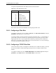
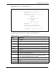
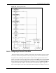
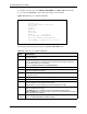
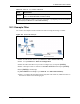
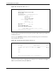
Table Of Contents
- P-2302R Series
- User’s Guide
- Copyright
- Federal Communications Commission (FCC) Interference Statement
- Safety Warnings
- ZyXEL Limited Warranty
- Customer Support
- Table of Contents
- List of Figures
- List of Tables
- Preface
- Introducing the Prestige
- Introducing the Web Configurator
- Wizard Setup
- System Screens
- LAN Setup
- WAN Screens
- Introduction to VoIP
- VoIP Screens
- Phone
- Phone Book
- Phone Usage
- Network Address Translation (NAT) Screens
- Static Route
- Firewall
- Content Filtering
- Remote Management Screens
- Universal Plug-and-Play (UPnP)
- Logs
- Bandwidth Management
- 19.1 Bandwidth Management Overview
- 19.2 Bandwidth Classes and Filters
- 19.3 Proportional Bandwidth Allocation
- 19.4 Application-based Bandwidth Management
- 19.5 Subnet-based Bandwidth Management
- 19.6 Application and Subnet-based Bandwidth Management
- 19.7 Scheduler
- 19.8 Maximize Bandwidth Usage
- 19.9 Bandwidth Borrowing
- 19.10 Configuring Summary
- 19.11 Configuring Class Setup
- 19.12 Configuring Monitor
- Maintenance
- Introducing the SMT
- General Setup
- WAN Setup
- LAN Setup
- Internet Access
- Remote Node Configuration
- Static Route Setup
- Network Address Translation (NAT)
- Enabling the Firewall
- Filter Configuration
- SNMP Configuration
- System Information and Diagnosis
- Firmware and Configuration File Maintenance
- 33.1 Filename Conventions
- 33.2 Backup Configuration
- 33.2.1 Backup Configuration
- 33.2.2 Using the FTP Command from the Command Line
- 33.2.3 Example of FTP Commands from the Command Line
- 33.2.4 GUI-based FTP Clients
- 33.2.5 TFTP and FTP over WAN Management Limitations
- 33.2.6 Backup Configuration Using TFTP
- 33.2.7 TFTP Command Example
- 33.2.8 GUI-based TFTP Clients
- 33.3 Restore Configuration
- 33.4 Uploading Firmware and Configuration Files
- System Maintenance
- Remote Management
- Call Scheduling
- Troubleshooting
- 37.1 Problems Starting Up the Prestige
- 37.2 Problems with the LAN Interface
- 37.3 Problems with the WAN Interface
- 37.4 Problems with Internet Access
- 37.5 Problems with the Password
- 37.6 Problems with the Web Configurator
- 37.7 Problems with a Telephone or the Telephone Port
- 37.8 Problems with Voice Service
- 37.9 Pop-up Windows, JavaScripts and Java Permissions
- Product Specifications
- Wall-mounting Instructions
- Setting up Your Computer’s IP Address
- IP Subnetting
- PPPoE
- Triangle Route
- SIP Passthrough
- Index
P-2302R Series User’s Guide
Chapter 30 Filter Configuration 288
M = N means an action can be taken immediately. The action is to drop the packet (m = D) if
the action is matched and to forward the packet immediately (n = F) if the action is not
matched no matter whether there are more rules to be checked (there aren’t in this example).
After you’ve created the filter set, you must apply it.
1 Enter 11 from the main menu to go to menu 11.
2 Go to the Edit Filter Sets field, press [SPACE BAR] to select Yes and press [ENTER].
3 This brings you to menu 11.5. Apply a filter set (our example filter set 3).
4 Press [ENTER] to confirm after you enter the set numbers and to leave menu 11.5.
30.4 Filter Types and NAT
There are two classes of filter rules, Generic Filter (Device) rules and protocol filter (TCP/
IP) rules. Generic filter rules act on the raw data from/to LAN and WAN. Protocol filter rules
act on the IP packets. Generic and TCP/IP filter rules are discussed in more detail in the next
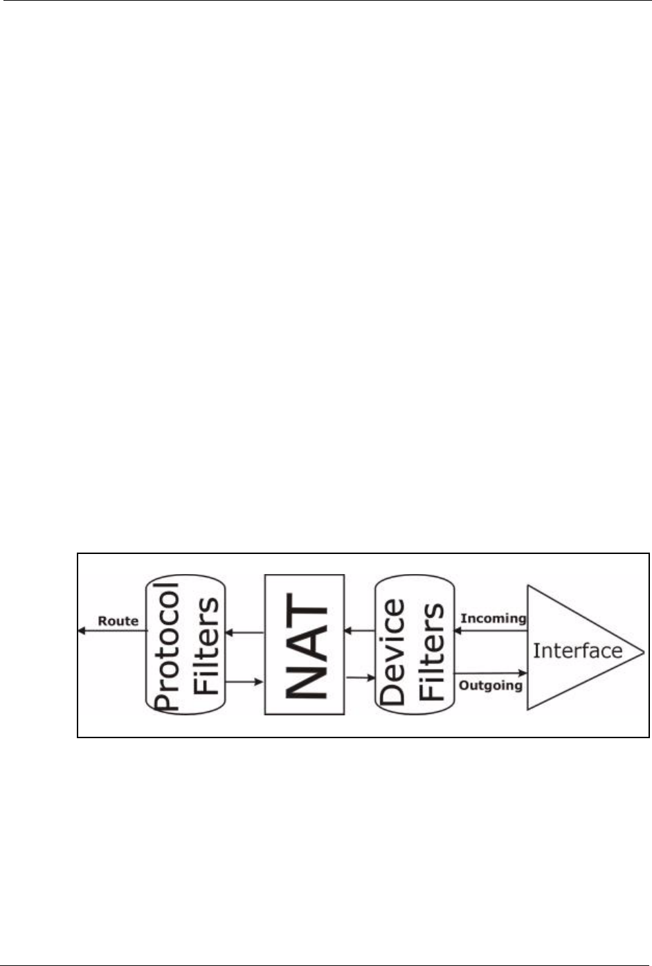
section. When NAT (Network Address Translation) is enabled, the inside IP address and port
number are replaced on a connection-by-connection basis, which makes it impossible to know
the exact address and port on the wire. Therefore, the Prestige applies the protocol filters to the
“native” IP address and port number before NAT for outgoing packets and after NAT for
incoming packets. On the other hand, the generic, or device filters are applied to the raw
packets that appear on the wire. They are applied at the point when the Prestige is receiving
and sending the packets; i.e. the interface. The interface can be an Ethernet port or any other
hardware port. The following diagram illustrates this.
Figure 160 Protocol and Device Filter Sets
30.5 Applying a Filter
This section shows you where to apply the filter(s) after you design it (them).