Prestige 652H/HW ADSL Security/Wireless LAN Router Compact Guide Version 3.
Prestige 652H/HW Table of Contents 1 Introducing the Prestige ................................................................................................................ 1 2 Hardware ........................................................................................................................................ 2 2.1 Rear Panel Connections............................................................................................................. 3 2.2 Inserting a PCMCIA Wireless LAN Card......
Prestige 652H/HW You should have an Internet account already set up and have been given most of the following information.
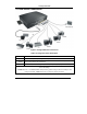
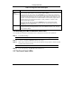
Prestige 652H/HW 2.1 Rear Panel Connections Figure 1 Prestige Hardware Connections Table 1 Prestige Rear Panel Description LABEL DESCRIPTION 1. DSL Connect to a telephone jack using the included phone wire. 2. LAN 1/DMZ-4 Connect to a computer/external hub using an Ethernet cable. Connect the DMZ port to servers that you want visible to the outside world. 3. POWER Connect to a power source using the power adaptor for your region (see your User’s Guide).
Prestige 652H/HW Table 1 Prestige Rear Panel Description LABEL DESCRIPTION CON/AUX switch CON/AUX port Only connect this port if you want to configure the Prestige using the SMT via console port or set up a backup WAN connection; see your User’s Guide for details. Set this switch to the “CON” side to use the CON/AUX port as a console port for local device configuration and management.
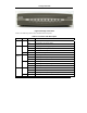
Prestige 652H/HW Figure 2 Prestige Front Panel Refer to the following table for more detailed LED descriptions. Table 2 Front Panel LED Description LED PWR SYS LAN 1/DMZ-4 COLOR Green DESCRIPTION On The Prestige is receiving power. Off The Prestige is not receiving power. On The Prestige is functioning properly. Blinking The Prestige is restarting. Off The system is not ready or has malfunctioned. Red On Power to the Prestige is too low.
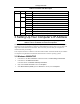
Prestige 652H/HW Table 2 Front Panel LED Description LED AUX COLOR Orange Green DSL Green ACT/PPP Orange Green STATUS DESCRIPTION On The CON/AUX port has a dial-up connection. Off The CON/AUX port does not have a dial-up connection. On The CON/AUX port has a console connection. Off The CON/AUX port does not have a console connection. On The Prestige is linked successfully to a DSLAM. Blinking The Prestige is initializing the DSL line. Off The DSL link is down.
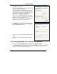
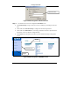
Prestige 652H/HW 5. The Internet Protocol TCP/IP Properties screen opens (the General tab in Windows XP). - To have your computer assigned a dynamic IP address, click Obtain an IP address automatically. If you know your DNS sever IP address(es), type them in the Preferred DNS server and/or Alternate DNS server fields. -To configure a static IP address, click Use the following IP Address and fill in the IP address (choose one from192.168.1.2 to 192.168.1.254), Subnet mask (255.255.255.
Prestige 652H/HW Refer to your User’s Guide for detailed IP address configuration for other Windows and Macintosh computer operating systems. 3.3 Testing the Connection to the Prestige 1. Click Start, (All) Programs, Accessories and then Command Prompt. 2. In the Command Prompt window, type "ping” followed by a space and the IP address of the Prestige (192.168.1.1 is the default). 3. Press ENTER and the following screen displays. C:\>ping 192.168.1.1 Pinging 192.168.1.
Prestige 652H/HW Default user name. Figure 4 Web Configurator: Password Screen Step 3. You should now see the web configurator SITE MAP screen. Click Wizard Setup to begin a series of screens to configure your Prestige for the first time. Click a link under Advanced Setup to configure advanced Prestige features. Click a link under Maintenance to see Prestige performance statistics, upload firmware and back up, restore or upload a configuration file.
Prestige 652H/HW The Prestige automatically logs you out if it is left idle for five minutes; press ENTER to log back in again. 4.2 Common Screen Command Buttons The following table shows common command buttons found on many web configurator screens. Back Click Back to return to the previous screen. Apply Click Apply to save your changes back to the Prestige. Reset/Cancel Click Reset or Cancel to begin configuring this screen afresh. 4.
Prestige 652H/HW If your ISP provides the name of your PPPoE service provider, enter it in the Service Name field. Enter the user name and password exactly as your ISP assigned them. Select Obtain an IP Address Automatically if you have a dynamic IP address; otherwise select Static IP Address and type your ISP assigned IP address in the text box below. Select Connect on Demand when you don't want the connection up all the time and specify an idle time-out period (in seconds) in the Max. Idle Timeout field.
Prestige 652H/HW In the ENET ENCAP Gateway field, enter the gateway IP address given by your ISP. Refer to Figure 7 for other field descriptions. Figure 9 Internet Connection with ENET ENCAP Refer to Figure 7 for field descriptions. The IP Address and Network Address Translation fields are not available for bridge mode. Figure 10 Internet Connection with PPPoA Step 3. Verify the settings in the screen shown next. To change the LAN information on the Prestige, click Change LAN Configurations.
Prestige 652H/HW Figure 11 Wizard Screen 3 Step 4. If you want to change your Prestige LAN settings, click Change LAN Configuration to display the screen as shown next. Enter the IP address of your Prestige in dotted decimal notation in the LAN IP Address field. For example, 192.168.1.1 (factory default). If you change the Prestige’s LAN IP address, you must use the new IP address if you want to access the web configurator again.
Prestige 652H/HW Step 5. The Prestige automatically tests the connection to the computer(s) connected to the LAN ports. To test the connection from the Prestige to the ISP, click Start Diagnose. Otherwise click Return to Main Menu to go back to the Site Map screen. Figure 13 Wizard Screen 4 4.4 Test Your Internet Connection Launch your web browser and navigate to www.zyxel.com. Internet access is just the beginning.
Prestige 652H/HW Figure 14 Wireless LAN: Wireless The following table describes the fields in this screen. Table 3 Wireless LAN: Wireless LABEL DESCRIPTION ESSID (Extended Service Set IDentity) The ESSID is a unique name to identify the Prestige in the wireless LAN. Wireless clients associating to an Access Point (the Prestige) must have the same ESSID. Enter a descriptive name (up to 32 printable 7-bit ASCII characters).
Prestige 652H/HW Table 3 Wireless LAN: Wireless LABEL RTS/CTS Threshold DESCRIPTION Select this option to enable the RTS (Request To Send)/CTS (Clear To Send) threshold to minimize collisions. Enter a value between 0 and 2432. The default is 2432. Request To Send is the threshold (number of bytes) for enabling the RTS/CTS handshake. Data with its frame size larger than this value will perform the RTS/CTS handshake.
Prestige 652H/HW Figure 15 Wireless LAN: MAC Address Filter The following table describes the fields in this screen. Table 4 Wireless LAN: MAC Address Filter LABEL Active DESCRIPTION Select Yes from the drop down list box to enable MAC address filtering.
Prestige 652H/HW Table 4 Wireless LAN: MAC Address Filter LABEL DESCRIPTION Define the filter action for the list of MAC addresses in the MAC Address table. Select Deny Association to block access to the router, MAC addresses not listed will be allowed to access the router Action Select Allow Association to permit access to the router, MAC addresses not listed will be denied access to the router. MAC Address Enter the list of MAC addresses in this table. 5.
Prestige 652H/HW Step 1. From the main screen click Advanced Setup and then NAT to open the NAT-Mode screen. Select SUA Only. Figure 16 NAT: Mode Step 2. Click Edit Details. Figure 17 SUA/NAT Server The following table describes the fields in this screen.
Prestige 652H/HW Table 5 SUA/NAT Server LABEL DESCRIPTION Start Port No. Type a port number in this field. To forward only one port, type the port number again in the End Port field. To forward a series of ports, type the start port number here and the end port number in the End Port field. End Port No. Type a port number in this field. To forward only one port, type the port number in the Start Port field above and then type it again in this field.
Prestige 652H/HW Figure 18 Prestige Firewall Application 5.6 Enabling the Firewall From the main screen, click Advanced Setup, Firewall and then Config to open the Configuration screen. Enable (or activate) the firewall by selecting the Enable Firewall check box as seen in the following screen.
Prestige 652H/HW 5.7 Procedure for Configuring Firewall Rules From the main screen, click Advanced Setup, Firewall and then Rule Summary (for either local network to Internet rules or Internet to local network rules) to open the Summary screen. The following table describes the fields in this screen.
Prestige 652H/HW Table 6 Summary Screen LABEL DESCRIPTION Source IP This drop-down list box displays the source addresses or ranges of addresses to which this firewall rule applies. Please note that a blank source or destination address is equivalent to Any. Destination IP This drop-down list box displays the destination addresses or ranges of addresses to which this firewall rule applies. Please note that a blank source or destination address is equivalent to Any.
Prestige 652H/HW Figure 20 Creating/Editing A Firewall Rule The following table describes the fields in this screen. Table 7 Creating/Editing A Firewall Rule LABEL DESCRIPTION Source Address Click SrcAdd to add a new address, SrcEdit to edit an existing one or SrcDelete to delete one. Please see the next section for more information on adding and editing source addresses. Destination Address Click DestAdd to add a new address, DestEdit to edit an existing one or DestDelete to delete one.
Prestige 652H/HW Table 7 Creating/Editing A Firewall Rule LABEL DESCRIPTION Edit Available Service Click this button to go to the list of available custom services. Action for Matched Packets Should packets that match this rule be blocked or forwarded? Make your choice from the drop down list box. Note that Block means the firewall silently discards the packet. Log This field determines if a log is created for packets that match the rule, don’t match the rule, both or no log is created.
Prestige 652H/HW Table 8 Adding/Editing Source and Destination Addresses LABEL DESCRIPTION End IP Address Enter the ending IP address in a range here. Subnet Mask Enter the subnet mask here, if applicable. 5.9 VPN Overview A VPN (Virtual Private Network) provides secure communications between sites without the expense of leased site-to-site lines.
Prestige 652H/HW From the main screen, click Advanced Setup, VPN, and Setup to open the Summary screen. This is a read-only menu of your IPSec rules (tunnels). Figure 23 VPN Summary The following table describes the fields in this screen. Table 9 VPN Summary LABEL DESCRIPTION No. The VPN policy index number Name This field displays the identification name for this VPN policy. Active This field displays whether the VPN policy is active or not. A Yes signifies that this VPN policy is active.
Prestige 652H/HW Table 9 VPN Summary LABEL Remote Address DESCRIPTION This is the IP address(es) of computer(s) on the remote network behind the remote IPSec router. This field displays N/A when the Secure Gateway IP Address field displays 0.0.0.0. In this case only the remote IPSec router can initiate the VPN. The same (static) IP address is displayed twice when the Remote Address Type field in the Configure-IKE (or Manual) screen is configured to Single Address.
Prestige 652H/HW Figure 24 VPN IKE The following table describes the fields in this screen.
Prestige 652H/HW Table 10 VPN IKE LABEL DESCRIPTION Active Select this check box to activate this VPN tunnel. This option determines whether a VPN rule is applied before a packet leaves the firewall. Keep Alive Select either Yes or No from the drop-down list box. Select Yes to have the Prestige automatically re-initiate the SA after the SA lifetime times out, even if there is no traffic. The remote IPSec router must also have keep alive enabled in order for this feature to work.
Prestige 652H/HW Table 10 VPN IKE LABEL DESCRIPTION Remote Address Type Use the drop-down menu to choose Single, Range, or Subnet. Select Single with a single IP address. Select Range for a specific range of IP addresses. Select Subnet to specify IP addresses on a network by their subnet mask. IP Address Start When the Address Type field is configured to Single, enter a (static) IP address on the network behind the remote IPSec router.
Prestige 652H/HW Table 10 VPN IKE LABEL Content DESCRIPTION When you select IP in the Peer ID Type field, type the IP address of the computer with which you will make the VPN connection or leave the field blank to have the Prestige automatically use the address in the Secure Gateway IP Address field. When you select DNS in the Peer ID Type field, type a domain name (up to 31 characters) by which to identify the remote IPSec router.
Prestige 652H/HW Table 10 VPN IKE LABEL DESCRIPTION Authentication Algorithm Select SHA1 or MD5 from the drop-down list box. MD5 (Message Digest 5) and SHA1 (Secure Hash Algorithm) are hash algorithms used to authenticate packet data. The SHA1 algorithm is generally considered stronger than MD5, but is slower. Select MD5 for minimal security and SHA-1 for maximum security. Advanced Click Advanced to configure more detailed settings of your IKE key management. Delete Click Delete to remove this rule.
Prestige 652H/HW Figure 25 UPnP The following table describes the fields in this screen. Table 11 UPnP FIELD DESCRIPTION Enable the Universal Plug and Play (UPnP) Service Select this checkbox to activate UPnP. Be aware that anyone could use a UPnP application to open the web configurator's login screen without entering the Prestige's IP address (although you must still enter the password to access the web configurator).
Prestige 652H/HW 6 Troubleshooting Table 12 Troubleshooting PROBLEM CORRECTIVE ACTION None of the LEDs turn on when you turn on the Prestige. Make sure that you have the correct power adapter connected to the Prestige and plugged in to an appropriate power source. Check all cable connections. Cannot access the Prestige from the LAN. Check the cable connection between the Prestige and your computer or hub. Refer to the Rear Panel Connections section for details.