Prestige 645R-A series ADSL Router User's Guide Version 3.
Prestige 645R-A Series User’s Guide Copyright Copyright © 2003 by ZyXEL Communications Corporation. The contents of this publication may not be reproduced in any part or as a whole, transcribed, stored in a retrieval system, translated into any language, or transmitted in any form or by any means, electronic, mechanical, magnetic, optical, chemical, photocopying, manual, or otherwise, without the prior written permission of ZyXEL Communications Corporation. Published by ZyXEL Communications Corporation.
Prestige 645R-A Series User’s Guide Federal Communications Commission (FCC) Interference Statement This device complies with Part 15 of FCC rules. Operation is subject to the following two conditions: • This device may not cause harmful interference. • This device must accept any interference received, including interference that may cause undesired operations. This equipment has been tested and found to comply with the limits for a Class B digital device pursuant to Part 15 of the FCC Rules.
Prestige 645R-A Series User’s Guide ZyXEL Limited Warranty ZyXEL warrants to the original end user (purchaser) that this product is free from any defects in materials or workmanship for a period of up to two years from the date of purchase.
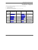
Prestige 645R-A Series User’s Guide Customer Support Please have the following information ready when you contact customer support. • • • • Product model and serial number. Warranty Information. Date that you received your device. Brief description of the problem and the steps you took to solve it. METHOD E-MAIL SUPPORT/SALES TELEPHONE/FAX WEB SITE/ FTP SITE REGULAR MAIL LOCATION WORLDWIDE support@zyxel.com.tw +886-3-578-3942 www.zyxel.com www.europe.zyxel.com sales@zyxel.com.
Prestige 645R-A Series User’s Guide Table of Contents ADSL Router.................................................................................................................................................... i Copyright......................................................................................................................................................... ii Federal Communications Commission (FCC) Interference Statement.....................................................
Prestige 645R-A Series User’s Guide 4.2.3 PPPoA ................................................................................................................................4-1 4.2.4 RFC 1483 ...........................................................................................................................4-2 4.3 Multiplexing...............................................................................................................................4-2 4.3.1 VC-based Multiplexing ...............
Prestige 645R-A Series User’s Guide 6.3 SUA Server ................................................................................................................................6-5 6.3.1 Port Forwarding: Services and Port Numbers....................................................................6-5 6.3.2 Configuring Servers Behind SUA (Example)....................................................................6-6 6.4 Selecting the NAT Mode ................................................................
Prestige 645R-A Series User’s Guide 12.3 IP Alias.....................................................................................................................................12-1 12.4 IP Alias Setup...........................................................................................................................12-2 12.5 Route IP Setup..........................................................................................................................12-4 12.
Prestige 645R-A Series User’s Guide 17.1 About Filtering.........................................................................................................................17-1 17.2 Configuring a Filter Set ...........................................................................................................17-4 17.2.1 Filter Rules Summary Menus ..........................................................................................17-6 17.3 Configuring a Filter Rule ............................
Prestige 645R-A Series User’s Guide 20.4 Uploading Firmware and Configuration Files..........................................................................20-8 20.4.1 Firmware File Upload ......................................................................................................20-8 20.4.2 Configuration File Upload ...............................................................................................20-9 20.4.3 FTP File Upload Command from the DOS Prompt Example .......................
Prestige 645R-A Series User’s Guide List of Figures Figure 1-1 Internet Access Application...........................................................................................................1-4 Figure 1-2 LAN-to-LAN Application.............................................................................................................1-4 Figure 2-1 Front Panel ....................................................................................................................................
Prestige 645R-A Series User’s Guide Figure 11-2 Menu 3.1 General Ethernet Setup..............................................................................................11-1 Figure 11-3 Menu 3.2 TCP/IP and DHCP Ethernet Setup ............................................................................11-2 Figure 12-1 Physical Network ..................................................................................................................... 12-2 Figure 12-2 Partitioned Logical Networks.........
Prestige 645R-A Series User’s Guide Figure 16-15 NAT Example 3.....................................................................................................................16-14 Figure 16-16 Example 3: Menu 11.3 ..........................................................................................................16-15 Figure 16-17 Example 3: Menu 15.1.1.1 ....................................................................................................
Prestige 645R-A Series User’s Guide Figure 20-6 Telnet Into Menu 24.7.2 System Maintenance ......................................................................... 20-9 Figure 20-7 FTP Session Example of Firmware File Upload .................................................................... 20-10 Figure 21-1 Menu 25 IP Routing Policy Setup ............................................................................................ 21-2 Figure 21-2 Menu 25.1 IP Routing Policy Setup .......................
Prestige 645R-A Series User’s Guide List of Tables Table 2-1 Front Panel LED Description .........................................................................................................2-1 Table 3-1 Password.........................................................................................................................................3-3 Table 4-1 Wizard Screen 1..............................................................................................................................
Prestige 645R-A Series User’s Guide Table 17-1 Abbreviations Used in the Filter Rules Summary Menu............................................................ 17-6 Table 17-2 Rule Abbreviations Used ........................................................................................................... 17-7 Table 17-3 Menu 21.x.1 TCP/IP Filter Rule ................................................................................................ 17-9 Table 17-4 Menu 21.6.1 Generic Filter Rule..............
Prestige 645R-A Series User’s Guide List of Charts Chart A-1 Troubleshooting Power LED ........................................................................................................A-1 Chart A-2 Troubleshooting LAN LED ..........................................................................................................A-1 Chart A-3 Troubleshooting DSL LED ...........................................................................................................
Prestige 645R-A Series User’s Guide Preface Congratulations on your purchase from the Prestige 645R-A ADSL Router series. Your Prestige is easy to install and configure. Use the web configurator, System Management Terminal (SMT) or command interpreter interface to configure your Prestige. Not all features can be configured through all interfaces. Don’t forget to register your Prestige online at www.zyxel.com for free future product updates and information.
Prestige 645R-A Series User’s Guide • For brevity’s sake, we will use “e.g.,” as a shorthand for “for instance”, and “i.e.,” for “that is” or “in other words” throughout this manual. • The Prestige 645R-A series may be referred to as the Prestige in this user’s guide. The following section offers some background information on DSL. Skip to Chapter 1 if you wish to begin working with your router right away. User Guide Feedback Help us help you.
Prestige 645R-A Series User’s Guide Introduction to DSL DSL (Digital Subscriber Line) technology enhances the data capacity of the existing twisted-pair wire that runs between the local telephone company switching offices and most homes and offices.
Getting Started Part I: Getting Started This part is structured as a step-by-step guide to help you access your Prestige. It covers key features and applications, accessing the web configurator and configuring the wizard screens for initial setup.
Prestige 645R-A Series User’s Guide Chapter 1 Getting To Know Your Prestige This chapter describes the key features and applications of your Prestige. 1.1 Introducing the Prestige 645R-A Series Your Prestige integrates a high-speed 10/100Mbps auto-negotiating LAN interface and a high-speed DSL port into a single package. The Prestige is ideal for high-speed Internet browsing and making LAN-to-LAN connections to remote networks.
Prestige 645R-A Series User’s Guide • • • Transparent bridging for unsupported network layer protocols. DHCP Client, Server and Relay RIP I and RIP II IP Policy Routing IP Policy Routing (IPPR) provides a mechanism to override the default routing behavior and alter the packet forwarding based on the policy defined by the network administrator. Call Scheduling Configure call time periods to allow and restrict access to remote nodes.
Prestige 645R-A Series User’s Guide PAP and CHAP Security The Prestige supports PAP (Password Authentication Protocol) and CHAP (Challenge Handshake Authentication Protocol). CHAP is more secure since the password is scrambled prior to transmission. However, PAP is readily available on more platforms. Filters The Prestige's packet filtering functions allow added network security and management. Reset Button The Prestige comes with a reset button built into the rear panel.
Prestige 645R-A Series User’s Guide Figure 1-1 Internet Access Application 1.3.2 LAN to LAN Application You can use the Prestige to connect two geographically dispersed networks through an ADSL line. A typical LAN-to-LAN application for your Prestige is shown as follows.
Prestige 645R-A Series User’s Guide Chapter 2 Hardware Installation This chapter describes the physical features and cable connections of the Prestige. 2.1 Front Panel LEDs of the Prestige The LED indicators on the front panel indicate the operational status of the Prestige Figure 2-1 Front Panel The table below describes the status of the front panel LEDs. Table 2-1 Front Panel LED Description LED PWR SYS LAN 10M COLOR STATUS Green On The Prestige is receiving power.
Prestige 645R-A Series User’s Guide Table 2-1 Front Panel LED Description LED LAN 100M DSL COLOR STATUS Orange On The Prestige has a successful 100Mb Ethernet connection. Blinking The Prestige is receiving or sending data. Off No device is connected at 100Mb. On The Prestige is linked successfully to a DSLAM. Blinking The Prestige is initializing the DSL line. Off The DSL link is down. Blinking The Prestige is receiving or sending data.
Prestige 645R-A Series User’s Guide 2.2.2 One Auto-crossover LAN 10/100M Port Ethernet 10Base-T/100Base-T networks use Shielded Twisted Pair (STP) cable with RJ-45 that look like a bigger telephone plug with 8 pins. The LAN port is auto-crossover, so you may use a crossover or a straightthrough Ethernet cable to connect your Prestige to a computer or an external hub. When the Prestige is on and properly connected to a computer or a hub, the LAN LED on the front panel turns on. 2.2.
Prestige 645R-A Series User’s Guide 2.4 Turning On Your Prestige At this point, you should have connected the DSL line, the LAN port and the power port to the appropriate devices or lines.
Prestige 645R-A Series User’s Guide Chapter 3 Introducing the Web Configurator This chapter describes how to access and navigate the web configurator. 3.1 Web Configurator Overview The embedded web configurator allows you to manage the Prestige from anywhere through a browser such as Microsoft Internet Explorer or Netscape Navigator. Use Internet Explorer 6.0 and later or Netscape Navigator 7.0 and later versions with JavaScript enabled.
Prestige 645R-A Series User’s Guide Step 6. You should now see the Site Map screen. The Prestige automatically times out after five minutes of inactivity. Simply log back into the Prestige if this happens to you. 3.3 Navigating the Prestige Web Configurator The following summarizes how to navigate the web configurator from the Site Map screen. Screens vary slightly for different Prestige models. Click Wizard Setup to begin a series of screens to configure your Prestige for the first time.
Prestige 645R-A Series User’s Guide 3.4 Configuring Password It is highly recommended that you change the password for accessing the Prestige. To change your Prestige’s password, click Advanced Setup and then Password. The screen appears as shown. Figure 3-3 Password The following table describes the labels in this screen. Table 3-1 Password LABEL DESCRIPTION Old Password Type the default password or the existing password you use to access the system in this field.
Prestige 645R-A Series User’s Guide 3.5 Resetting the Prestige If you forget your password or cannot access the Prestige, you will need to reload the factory-default configuration file or use the RESET button the back of the Prestige. Uploading this configuration file replaces the current configuration file with the factory-default configuration file. This means that you will lose all configurations that you had previously. The password will be reset to “1234”, also. 3.5.
Prestige 645R-A Series User’s Guide Chapter 4 Wizard Setup This chapter provides information on the Wizard Setup screens in the web configurator. 4.1 Wizard Setup Introduction Use the Wizard Setup screens to configure your system for Internet access settings and fill in the fields with the information in the Internet Access Checklist table of the Read Me First. Your ISP may have already configured some of the fields in the wizard screens for you. 4.
Prestige 645R-A Series User’s Guide 4.2.4 RFC 1483 RFC 1483 describes two methods for Multiprotocol Encapsulation over ATM Adaptation Layer 5 (AAL5). The first method allows multiplexing of multiple protocols over a single ATM virtual circuit (LLC-based multiplexing) and the second method assumes that each protocol is carried over a separate ATM virtual circuit (VC-based multiplexing). Please refer to the RFC for more detailed information. 4.
Prestige 645R-A Series User’s Guide Figure 4-1 Wizard Screen 1 The following table describes the labels in this screen. Table 4-1 Wizard Screen 1 LABEL Protocol Wizard Setup DESCRIPTION This field contains some pre-configured encapsulation/multiplexing combinations.
Prestige 645R-A Series User’s Guide Table 4-1 Wizard Screen 1 LABEL DESCRIPTION Virtual Circuit ID VPI (Virtual Path Identifier) and VCI (Virtual Channel Identifier) define a virtual circuit. Refer to the appendix for more information. VPI Enter the VPI assigned to you. This field may already be configured. VCI Enter the VCI assigned to you. This field may already be configured. ATM QoS Type Select CBR (Continuous Bit Rate) to specify fixed (always-on) bandwidth for voice or data traffic.
Prestige 645R-A Series User’s Guide Network Address Translation (NAT) feature of the Prestige. The Internet Assigned Number Authority (IANA) reserved this block of addresses specifically for private use; please do not use any other number unless you are told otherwise. Let's say you select 192.168.1.0 as the network number; which covers 254 individual addresses, from 192.168.1.1 to 192.168.1.254 (zero and 255 are reserved).
Prestige 645R-A Series User’s Guide 4.7.4 Private IP Addresses Every machine on the Internet must have a unique address. If your networks are isolated from the Internet, for example, only between your two branch offices, you can assign any IP addresses to the hosts without problems. However, the Internet Assigned Numbers Authority (IANA) has reserved the following three blocks of IP addresses specifically for private networks: 10.0.0.0 — 10.255.255.255 172.16.0.0 — 172.31.255.255 192.168.0.0 — 192.
Prestige 645R-A Series User’s Guide 4.10.1 PPPoE Select PPPoE from the Protocol drop-down list box in the first wizard screen to display the screen as shown. Figure 4-2 Internet Connection with PPPoE The following table describes the labels in this screen. Table 4-2 Internet Connection with PPPoE LABEL DESCRIPTION Service Name Type the name of your PPPoE service here. User Name Configure User Name and Password fields for PPPoA and PPPoE encapsulation only.
Prestige 645R-A Series User’s Guide Table 4-2 Internet Connection with PPPoE LABEL IP Address DESCRIPTION A static IP address is a fixed IP that your ISP gives you. A dynamic IP address is not fixed; the ISP assigns you a different one each time you connect to the Internet. The Single User Account feature can be used with either a dynamic or static IP address.
Prestige 645R-A Series User’s Guide The following table describes the labels in this screen. Table 4-3 Internet Connection with RFC 1483 LABEL DESCRIPTION IP Address Type your ISP assigned IP address in this field. Back Click Back to go back to the first wizard screen. Finish Click Finish to save the settings and proceed to the next wizard screen. 4.10.3 ENET ENCAP Select ENET ENCAP from the Encapsulation drop-down list box in the first wizard screen to display the screen as shown.
Prestige 645R-A Series User’s Guide Table 4-4 Internet Connection with ENET ENCAP LABEL IP Address DESCRIPTION A static IP address is a fixed IP that your ISP gives you. A dynamic IP address is not fixed; the ISP assigns you a different one each time you connect to the Internet. The Single User Account feature can be used with either a dynamic or static IP address.
Prestige 645R-A Series User’s Guide Figure 4-5 Internet Connection with PPPoA The following table describes the labels in this screen. Table 4-5 Internet Connection with PPPoA LABEL DESCRIPTION User Name Enter the user name exactly as your ISP assigned. If assigned a name in the form user@domain where domain identifies a service name, then enter both components exactly as given. Password Enter the password associated with the user name above.
Prestige 645R-A Series User’s Guide Table 4-5 Internet Connection with PPPoA LABEL Connection DESCRIPTION Select Connect on Demand when you don't want the connection up all the time and specify an idle time-out (in seconds) in the Max. Idle Timeout field. The default setting selects Connection on Demand with 0 as the idle time-out, which means the Internet session will not timeout. Select Nailed-Up Connection when you want your connection up all the time.
LAN, NAT and Dynamic DNS Part II: LAN, NAT and Dynamic DNS This part covers LAN (Local Area Network) setup, NAT (Network Address Translation) and dynamic DNS (Domain Name Sever).
Prestige 645R-A Series User’s Guide Chapter 5 LAN Setup This chapter describes how to configure LAN settings. 5.1 LAN Overview A Local Area Network (LAN) is a shared communication system to which many computers are attached. A LAN is a computer network limited to the immediate area, usually the same building or floor of a building. The LAN screens can help you configure a LAN DHCP server and manage IP addresses. 5.1.
Prestige 645R-A Series User’s Guide There are two ways that an ISP disseminates the DNS server addresses. The first is for an ISP to tell a customer the DNS server addresses, usually in the form of an information sheet, when s/he signs up. If your ISP gives you the DNS server addresses, enter them in the DNS Server fields in DHCP Setup, otherwise, leave them blank. Some ISP’s choose to pass the DNS servers using the DNS server extensions of PPP IPCP (IP Control Protocol) after the connection is up.
Prestige 645R-A Series User’s Guide These parameters should work for the majority of installations. If your ISP gives you explicit DNS server address(es), read the embedded web configurator help regarding what fields need to be configured. 5.4.2 IP Address and Subnet Mask Refer to the IP Address and Subnet Mask section in the Wizard Setup chapter for this information. 5.4.3 RIP Setup RIP (Routing Information Protocol) allows a router to exchange routing information with other routers.
Prestige 645R-A Series User’s Guide 5.5 Configuring LAN Click LAN to open the following screen. Figure 5-2 LAN The following table describes the labels in this screen.
Prestige 645R-A Series User’s Guide Table 5-1 LAN LABEL DESCRIPTION DHCP If set to Server, your Prestige can assign IP addresses, an IP default gateway and DNS servers to Windows 95, Windows NT and other systems that support the DHCP client. If set to None, the DHCP server will be disabled. If set to Relay, the Prestige acts as a surrogate DHCP server and relays DHCP requests and responses between the remote server and the clients.
Prestige 645R-A Series User’s Guide Chapter 6 Network Address Translation (NAT) This chapter discusses how to configure NAT on the Prestige. 6.1 NAT Overview NAT (Network Address Translation - NAT, RFC 1631) is the translation of the IP address of a host in a packet, for example, the source address of an outgoing packet, used within one network to a different IP address known within another network. 6.1.
Prestige 645R-A Series User’s Guide local address before forwarding it to the original inside host. Note that the IP address (either local or global) of an outside host is never changed. The global IP addresses for the inside hosts can be either static or dynamically assigned by the ISP. In addition, you can designate servers, for example, a web server and a telnet server, on your local network and make them accessible to the outside world.
Prestige 645R-A Series User’s Guide 6.1.4 NAT Application The following figure illustrates a possible NAT application, where three inside LANs (logical LANs using IP Alias) behind the Prestige can communicate with three distinct WAN networks. More examples follow at the end of this chapter. Figure 6-2 NAT Application With IP Alias 6.1.5 NAT Mapping Types NAT supports five types of IP/port mapping. They are: 1.
Prestige 645R-A Series User’s Guide 4. Many-to-Many No Overload: In Many-to-Many No Overload mode, the Prestige maps each local IP address to a unique global IP address. 5. Server: This type allows you to specify inside servers of different services behind the NAT to be accessible to the outside world. Port numbers do not change for One-to-One and Many-to-Many No Overload NAT mapping types. The following table summarizes these types. Table 6-2 NAT Mapping Types TYPE 6.
Prestige 645R-A Series User’s Guide 1. Choose SUA Only if you have just one public WAN IP address for your Prestige. 2. Choose Full Feature if you have multiple public WAN IP addresses for your Prestige. 6.3 SUA Server A SUA server set is a list of inside (behind NAT on the LAN) servers, for example, web or FTP, that you can make visible to the outside world even though SUA makes your whole inside network appear as a single computer to the outside world.
Prestige 645R-A Series User’s Guide Many residential broadband ISP accounts do not allow you to run any server processes (such as a Web or FTP server) from your location. Your ISP may periodically check for servers and may suspend your account if it discovers any active services at your location. If you are unsure, refer to your ISP. The most often used port numbers are shown in the following table. Please refer to RFC 1700 for further information about port numbers.
Prestige 645R-A Series User’s Guide Figure 6-3 Multiple Servers Behind NAT Example 6.4 Selecting the NAT Mode Click NAT to open the following screen. Figure 6-4 NAT Mode The following table describes the labels in this screen.
Prestige 645R-A Series User’s Guide Table 6-4 NAT Mode LABEL DESCRIPTION None Select this radio button to disable NAT. SUA Only Select this radio button if you have just one public WAN IP address for your Prestige. The Prestige uses Address Mapping Set 1 in the NAT - Edit SUA/NAT Server Set screen. Edit Details Click this link to go to the NAT - Edit SUA/NAT Server Set screen. Full Feature Select this radio button if you have multiple public WAN IP addresses for your Prestige.
Prestige 645R-A Series User’s Guide Figure 6-5 Edit SUA/NAT Server Set The following table describes the labels in this screen. Table 6-5 Edit SUA/NAT Server Set LABEL Start Port No. NAT DESCRIPTION Enter a port number in this field. To forward only one port, enter the port number again in the End Port No. field. To forward a series of ports, enter the start port number here and the end port number in the End Port No. field.
Prestige 645R-A Series User’s Guide Table 6-5 Edit SUA/NAT Server Set LABEL DESCRIPTION End Port No. Enter a port number in this field. To forward only one port, enter the port number again in the Start Port No. field above and then enter it again in this field. To forward a series of ports, enter the last port number in a series that begins with the port number in the Start Port No. field above. IP Address Enter your server IP address in this field.
Prestige 645R-A Series User’s Guide Figure 6-6 Address Mapping Rules The following table describes the labels in this screen. Table 6-6 Address Mapping Rules LABEL DESCRIPTION Local Start IP This is the starting Inside Local IP Address (ILA). Local IP addresses are N/A for Server port mapping. Local End IP This is the end Inside Local IP Address (ILA). If your rule is for all local IP addresses, then enter 0.0.0.0 as the Local Start IP address and 255.255.255.255 as the Local End IP address.
Prestige 645R-A Series User’s Guide Table 6-6 Address Mapping Rules LABEL DESCRIPTION Type 1-1: One-to-one mode maps one local IP address to one global IP address. Note that port numbers do not change for the One-to-one NAT mapping type. M-1: Many-to-One mode maps multiple local IP addresses to one global IP address. This is equivalent to SUA (i.e., PAT, port address translation), ZyXEL's Single User Account feature that previous ZyXEL routers supported only.
Prestige 645R-A Series User’s Guide Table 6-7 Address Mapping Rule Edit LABEL DESCRIPTION Type Choose the port mapping type from one of the following. 1. One-to-One: One-to-One mode maps one local IP address to one global IP address. Note that port numbers do not change for One-to-one NAT mapping type. 2. Many-to-One: Many-to-One mode maps multiple local IP addresses to one global IP address. This is equivalent to SUA (i.e.
Prestige 645R-A Series User’s Guide Chapter 7 Dynamic DNS Setup This chapter discusses how to configure your Prestige to use Dynamic DNS. 7.1 Dynamic DNS Dynamic DNS allows you to update your current dynamic IP address with one or many dynamic DNS services so that anyone can contact you (in NetMeeting, CU-SeeMe, etc.). You can also access your FTP server or Web site on your own computer using a DNS-like address (for instance myhost.dhs.
Prestige 645R-A Series User’s Guide Figure 7-1 DDNS The following table describes the labels in this screen. Table 7-1 DDNS LABEL DESCRIPTION Active Select this check box to use dynamic DNS. Service Provider Select the name of your Dynamic DNS service provider. Host Name Type the domain name assigned to your Prestige by your Dynamic DNS provider. E-mail Address Type your e-mail address. User Type your user name. Password Type the password assigned to you.
Maintenance Part III: Maintenance This part covers the maintenance screens.
Prestige 645R-A Series User’s Guide Chapter 8 Maintenance This chapter displays system information such as ZyNOS firmware, port IP addresses and port traffic statistics. 8.1 Maintenance Overview Use the maintenance screens to view system information, upload new firmware, manage configuration and restart your Prestige. 8.2 System Status Screen Click System Status to open the following screen, where you can use to monitor your Prestige.
Prestige 645R-A Series User’s Guide Figure 8-1 System Status The following table describes the labels in this screen.
Prestige 645R-A Series User’s Guide Table 8-1 System Status LABEL DESCRIPTION System Status System Name This is the name of your Prestige. It is for identification purposes. ZyNOS F/W Version This is the ZyNOS firmware version and the date created. ZyNOS is ZyXEL's proprietary Network Operating System design. DSL FW Version This is the DSL firmware version associated with your Prestige. Standard This is the standard that your Prestige is using. WAN Information IP Address This is the WAN port IP address.
Prestige 645R-A Series User’s Guide Table 8-1 System Status LABEL Show Statistics DESCRIPTION Click Show Statistics to see router performance statistics such as number of packets sent and number of packets received for each port. 8.2.1 System Statistics Click Show Statistics in the System Status screen to open the following screen. Read-only information here includes port status and packet specific statistics. Also provided are "system up time" and "poll interval(s)".
Prestige 645R-A Series User’s Guide The following table describes the labels in this screen. Table 8-2 System Status: Show Statistics LABEL System up Time DESCRIPTION This is the elapsed time the system has been up. WAN Port Statistics This is the WAN port. Link Status This is the status of your WAN link. Upstream Speed This is the upstream speed of your Prestige. Downstream Speed This is the downstream speed of your Prestige. Node-Link This field displays the remote node index number and link type.
Prestige 645R-A Series User’s Guide Table 8-2 System Status: Show Statistics LABEL DESCRIPTION Set Interval Click this button to apply the new poll interval you entered in the Poll Interval field above. Stop Click this button to halt the refreshing of the system statistics. 8.3 DHCP Table Screen DHCP (Dynamic Host Configuration Protocol, RFC 2131 and RFC 2132) allows individual clients to obtain TCP/IP configuration at start-up from a server.
Prestige 645R-A Series User’s Guide Table 8-3 DHCP Table LABEL MAC Address DESCRIPTION This field displays the MAC (Media Access Control) address of the computer with the displayed host name. Every Ethernet device has a unique MAC address. The MAC address is assigned at the factory and consists of six pairs of hexadecimal characters, for example, 00:A0:C5:00:00:02. 8.4 Diagnostic Screens These read-only screens display information to help you identify problems with the Prestige.
Prestige 645R-A Series User’s Guide Figure 8-5 Diagnostic General The following table describes the labels in this screen. Table 8-4 Diagnostic General LABEL DESCRIPTION TCP/IP Address Type the IP address of a computer that you want to ping in order to test a connection. Ping Click this button to ping the IP address that you entered. Reset System Click this button to reboot the Prestige. A warning dialog box is then displayed asking you if you're sure you want to reboot the system.
Prestige 645R-A Series User’s Guide Table 8-4 Diagnostic General LABEL Back DESCRIPTION Click this button to go back to the main Diagnostic screen. 8.4.2 Diagnostic DSL Line Screen Click Diagnostic and then DSL Line to open the screen shown next. Figure 8-6 Diagnostic DSL Line The following table describes the labels in this screen.
Prestige 645R-A Series User’s Guide Table 8-5 Diagnostic DSL Line LABEL Reset ADSL Line DESCRIPTION Click this button to reinitialize the ADSL line. The large text box above then displays the progress and results of this operation, for example: "Start to reset ADSL Loading ADSL modem F/W... Reset ADSL Line Successfully!" ATM Status Click this button to view ATM status. ATM Loopback Test Click this button to start the ATM loopback test.
Prestige 645R-A Series User’s Guide Figure 8-7 Firmware Upgrade The following table describes the labels in this screen. Table 8-6 Firmware Upgrade LABEL DESCRIPTION File Path Type in the location of the file you want to upload in this field or click Browse ... to find it. Browse... Click Browse... to find the .bin file you want to upload. Remember that you must decompress compressed (.zip) files before you can upload them. Upload Click Upload to begin the upload process.
Prestige 645R-A Series User’s Guide The Prestige automatically restarts in this time causing a temporary network disconnect. In some operating systems, you may see the following icon on your desktop. Figure 8-8 Network Temporarily Disconnected After two minutes, log in again and check your new firmware version in the System Status screen. If the upload was not successful, the following screen will appear. Click Back to go back to the Firmware screen.
SMT General Configuration Part IV: SMT General Configuration This part covers System Management Terminal configuration for general setup, Ethernet setup, Internet access, remote nodes, remote node TCP/IP, static routing and NAT. See the web configurator parts of this guide for background information on features configurable by web configurator and SMT.
Prestige 645R-A Series User’s Guide Chapter 9 Introducing the SMT This chapter explains how to access and navigate the System Management Terminal and gives an overview of its menus. 9.1 SMT Introduction The Prestige’s SMT (System Management Terminal) is a menu-driven interface that you can access from a terminal emulator through the console port or over a telnet connection. 9.1.1 Procedure for SMT Configuration via Telnet The following procedure details how to telnet into your Prestige. Step 1.
Prestige 645R-A Series User’s Guide Prestige Main Menu Menu 1 General Setup Menu 3 Ethernet Setup Menu 1.1 Configure Dynamic DNS Menu 3.2.1 IP Alias Setup Menu 4 Internet Access Setup Menu 11 Remote Node Setup Menu 12 Static Route Setup Menu 3.1 General Ethernet Setup Menu 11.1 Remote Node Profile Menu 12.1 IP Static Route Setup Menu 12.1.1 Edit IP Static Route Menu 15.1 Address Mapping Sets Menu 15.1.x Address Mapping Rules Menu 3.2 TCP/IP and DHCP Ethernet Setup Menu 11.
Prestige 645R-A Series User’s Guide Table 9-1 Main Menu Commands OPERATION KEYSTROKE DESCRIPTION Move down to another menu [ENTER] To move forward to a submenu, type in the number of the desired submenu and press [ENTER]. Move up to a previous menu [ESC] Press [ESC] to move back to the previous menu. Move to a “hidden” Press [SPACE Fields beginning with “Edit” lead to hidden menus and have a BAR] to change No default setting of No.
Prestige 645R-A Series User’s Guide Copyright (c) 1994 - 2003 ZyXEL Communications Corp. Prestige 645R-A Main Menu Getting Started 1. General Setup 3. Ethernet Setup 4. Internet Access Setup Advanced Applications 11. Remote Node Setup 12. Static Routing Setup 15. NAT Setup Advanced Management 21. Filter Set Configuration 22. SNMP Configuration 23. System Password 24. System Maintenance 25. IP Routing Policy Setup 26. Schedule Setup 99. Exit Enter Menu Selection Number: Figure 9-3 SMT Main Menu 9.2.
Prestige 645R-A Series User’s Guide 9.3 Changing the System Password Change the Prestige default password by following the steps shown next. Step 1. Enter 23 in the main menu to display Menu 23 - System Security as shown next. Step 2. Type your existing system password in the Old Password field, for example “1234”, and press [ENTER]. Menu 23 – System Password Old Password= ? New Password= ? Retype to confirm= ? Enter here to CONFIRM or ESC to CANCEL: Figure 9-4 Menu 23 System Password Step 3.
Prestige 645R-A Series User’s Guide Chapter 10 General Setup Menu 1 - General Setup contains administrative and system-related information. 10.1 General Setup Menu 1 — General Setup contains administrative and system-related information (shown next). The System Name field is for identification purposes. However, because some ISPs check this name you should enter your computer's "Computer Name". • In Windows 95/98 click Start, Settings, Control Panel, Network.
Prestige 645R-A Series User’s Guide Menu 1 - General Setup System Name= P645R-A1 Location= Contact Person's Name= Domain Name= Edit Dynamic DNS= No Route IP= Yes Bridge= No Press ENTER to Confirm or ESC to Cancel: Figure 10-1 Menu 1 General Setup Fill in the required fields. Refer to the table shown next for more information about these fields. Table 10-1 Menu 1 General Setup FIELD DESCRIPTION EXAMPLE System Name Enter a descriptive name for identification purposes.
Prestige 645R-A Series User’s Guide 10.2.1 Configuring Dynamic DNS If you have a private WAN IP address, then you cannot use Dynamic DNS. To configure Dynamic DNS, go to Menu 1 — General Setup and select Yes in the Edit Dynamic DNS field. Press [ENTER] to display Menu 1.1— Configure Dynamic DNS as shown next. Menu 1.1 - Configure Dynamic DNS Service Provider = WWW.DynDNS.ORG Active= Yes Host= me.ddns.
Prestige 645R-A Series User’s Guide Chapter 11 Ethernet Setup This chapter covers how to configure your wired Local Area Network (LAN) settings. 11.1 Ethernet Setup This section describes how to configure the Ethernet using Menu 3 — Ethernet Setup. From the main menu, enter 3 to display menu 3. Menu 3 - Ethernet Setup 1. General Setup 2. TCP/IP and DHCP Setup Enter Menu Selection Number: Figure 11-1 Menu 3 Ethernet Setup 11.1.
Prestige 645R-A Series User’s Guide 11.2 Protocol Dependent Ethernet Setup Depending on the protocols for your applications, you need to configure the respective Ethernet Setup, as outlined below. For TCP/IP Ethernet setup refer to the Internet Access Application chapter. For bridging Ethernet setup refer to the Bridging Setup chapter. 11.3 TCP/IP Ethernet Setup and DHCP Use menu 3.2 to configure your Prestige for TCP/IP. To edit menu 3.2, enter 3 from the main menu to display Menu 3 — Ethernet Setup.
Prestige 645R-A Series User’s Guide Table 11-1 DHCP Ethernet Setup Menu Fields FIELD DESCRIPTION EXAMPLE DHCP Setup DHCP If set to Server, your Prestige can assign IP addresses, an IP default gateway and DNS servers to Windows 95, Windows NT and other systems that support the DHCP client. If set to None, the DHCP server will be disabled. If set to Relay, the Prestige acts as a surrogate DHCP server and relays DHCP requests and responses between the remote server and the clients.
Prestige 645R-A Series User’s Guide Table 11-2 TCP/IP Ethernet Setup Menu Fields FIELD DESCRIPTION EXAMPLE Multicast IGMP (Internet Group Multicast Protocol) is a network-layer protocol used to establish membership in a Multicast group. The Prestige supports both IGMP version 1 (IGMP-v1) and version 2 (IGMP-v2). Press the [SPACE BAR] to enable IP Multicasting or select None to disable it.
Prestige 645R-A Series User’s Guide Chapter 12 Internet Access This chapter shows you how to configure the LAN and WAN of your Prestige for Internet access. 12.1 Internet Access Overview Refer to the chapters on the web configurator’s wizard, LAN and WAN screens for more background information on fields in the SMT screens covered in this chapter. 12.2 IP Policies Traditionally, routing is based on the destination address only and the router takes the shortest path to forward a packet.
Prestige 645R-A Series User’s Guide Figure 12-1 Physical Network Figure 12-2 Partitioned Logical Networks Use menu 3.2.1 to configure IP Alias on your Prestige. 12.4 IP Alias Setup Use menu 3.2 to configure the first network. Move the cursor to Edit IP Alias field and press [SPACEBAR] to choose Yes and press [ENTER] to configure the second and third network.
Prestige 645R-A Series User’s Guide Menu 3.2 - TCP/IP and DHCP Setup DHCP Setup: DHCP= Server Client IP Pool Starting Addres= 192.168.1.33 Size of Client IP Pool= 32 Primary DNS Server= 0.0.0.0 Secondary DNS Server= 0.0.0.0 Remote DHCP Server= N/A TCP/IP Setup: IP Address= 192.168.1.1 IP Subnet Mask= 255.255.255.0 RIP Direction= None Version= N/A Multicast= None IP Policies= Edit IP Alias= Yes Press ENTER to confirm or ESC to Cancel: Press Space Bar to Toggle. Figure 12-3 Menu 3.
Prestige 645R-A Series User’s Guide Table 12-1 Menu 3.2.1 IP Alias Setup FIELD DESCRIPTION IP Alias Choose Yes to configure the LAN network for the Prestige. IP Address Enter the IP address of your Prestige in dotted decimal notation IP Subnet Mask Your Prestige will automatically calculate the subnet mask based on the IP address that you assign. Unless you are implementing subnetting, use the subnet mask computed by the Prestige EXAMPLE Yes 192.168.1.1 255.255.255.
Prestige 645R-A Series User’s Guide 12.6 Internet Access Configuration Menu 4 allows you to enter the Internet Access information in one screen. Menu 4 is actually a simplified setup for one of the remote nodes that you can access in menu 11. Before you configure your Prestige for Internet access, you need to collect your Internet account information. Use the Internet Access Checklist table in the Read Me First to record your Internet account information.
Prestige 645R-A Series User’s Guide Table 12-2 Menu 4 Internet Access Setup FIELD DESCRIPTION EXAMPLE Multiplexing Press [SPACE BAR] to select the method of multiplexing used by your ISP. Choices are VC-based or LLC-based. VPI # Enter the Virtual Path Identifier (VPI) assigned to you. 8 VCI # Enter the Virtual Channel Identifier (VCI) assigned to you. 35 Service Name Only available when PPPoE encapsulation is used. Enter the name of your PPPoE service provider.
Prestige 645R-A Series User’s Guide Chapter 13 Remote Node Configuration This chapter covers remote node configuration. 13.1 Remote Node Setup Overview This section describes the protocol-independent parameters for a remote node. A remote node is required for placing calls to a remote gateway. A remote node represents both the remote gateway and the network behind it across a WAN connection. When you use menu 4 to set up Internet access, you are configuring one of the remote nodes.
Prestige 645R-A Series User’s Guide Menu 11 - Remote Node Setup 1. 2. 3. 4. 5. 6. 7. 8. My ISP (ISP, NAT) ________ ________ ________ ________ ________ ________ ________ Enter Node # to Edit: Figure 13-1 Menu 11 Remote Node Setup 13.2.2 Encapsulation and Multiplexing Scenarios For Internet access you should use the encapsulation and multiplexing methods used by your ISP.
Prestige 645R-A Series User’s Guide Menu 11.
Prestige 645R-A Series User’s Guide Table 13-1 Menu 11.1 Remote Node Profile FIELD Rem Login Rem Password DESCRIPTION EXAMPLE Type the login name that this remote node will use to call your Prestige. The login name and the Rem Password will be used to authenticate this node. Type the password used when this remote node calls your Prestige. Outgoing: My Login My Password Authen Type the login name assigned by your ISP when the Prestige calls this remote node.
Prestige 645R-A Series User’s Guide Table 13-1 Menu 11.1 Remote Node Profile FIELD Schedule Sets Nailed up Connection DESCRIPTION EXAMPLE This field is only applicable for PPPoE and PPPoA encapsulation. You can apply up to four schedule sets here. For more details please refer to the Call Scheduling chapter. This field is only applicable for PPPoE and PPPoA encapsulation. This field specifies if you want to make the connection to this remote node a nailed-up connection.
Prestige 645R-A Series User’s Guide The metric sets the priority for the Prestige’s routes to the Internet. If any two of the default routes have the same metric, the Prestige uses the following pre-defined priorities: 1. Normal route: designated by the ISP 2. Traffic-redirect route IP Policy Routing overrides the default routing behavior and takes priority over all of the routes mentioned above (see the IP Policy Routing chapter).
Prestige 645R-A Series User’s Guide Menu 11.3 - Remote Node Network Layer Options IP Options: IP Address Assignment= Dynamic Rem IP Addr: 0.0.0.0 Rem Subnet Mask= 0.0.0.0 My WAN Addr= 0.0.0.0 NAT= Full Feature Address Mapping Set= 2 Metric= 2 Private= No RIP Direction= None Version= RIP-1 Multicast= None IP Policies= 3,4,5,6 Bridge Options: Ethernet Addr Timeout (min)= N/A Press ENTER to Confirm or ESC to Cancel: Figure 13-3 Menu 11.
Prestige 645R-A Series User’s Guide Table 13-2 Menu 11.3 Remote Node Network Layer Options FIELD DESCRIPTION EXAMPLE Press [SPACE BAR] and then [ENTER] to select Full Feature if you have multiple public WAN IP addresses for your Prestige. NAT SUA Only Select SUA Only if you have just one public WAN IP address for your Prestige. The SMT uses Address Mapping Set 255 (menu 15.1 - see section 16.3.1). Select None to disable NAT.
Prestige 645R-A Series User’s Guide 13.4.1 My WAN Addr Sample IP Addresses The following figure uses sample IP addresses to help you understand the field of My Wan Addr in menu 11.3. Refer to the previous LAN and WAN IP Addresses figure in the web configurator chapter on LAN setup for a brief review of what a WAN IP is. My WAN Addr indicates the local Prestige WAN IP (172.16.0.1 in the following figure) while Rem IP Addr indicates the peer WAN IP (172.16.0.2 in the following figure).
Prestige 645R-A Series User’s Guide Note that spaces are accepted in this field. The Prestige has a prepackaged filter set, NetBIOS_WAN, that blocks NetBIOS packets (call protocol filter = 1). Include this in the call filter sets if you want to prevent NetBIOS packets from triggering calls to a remote node. Menu 11.
Prestige 645R-A Series User’s Guide Figure 13-7 Internet Security Once you apply the filter rules in the web configurator, filter sets 11 and 12 are automatically applied in the protocol filters field under Input Filter Sets in SMT menu 11.5. SMT input protocol filter set numbers that were previously applied are erased after you apply the Internet Security filter rules in the web configurator.
Prestige 645R-A Series User’s Guide Menu 21 - Filter Set Configuration Filter Set # -----1 2 3 4 5 6 Comments ----------------NetBIOS_WAN NetBIOS_LAN TELNET_WAN PPPoE FTP_WAN _______________ Filter Set # -----7 8 9 10 11 12 Comments ----------------_______________ _______________ _______________ _______________ WebSet1 WebSet2 Enter Filter Set Number to Configure= 0 Edit Comments= N/A Press ENTER to Confirm or ESC to Cancel: Figure 13-8 Menu 21- Filer Set Configuration The following figures display the
Prestige 645R-A Series User’s Guide Do not edit filter sets 11 and 12. They are used exclusively by the web configurator. Any rules you configured in sets 11 and 12 will be erased and replaced when you apply the web configurator-generated filter rules. 13.6 Editing ATM Layer Options Follow the steps shown next to edit Menu 11.6 – Remote Node ATM Layer Options. In menu 11.1, move the cursor to the Edit ATM Options field and then press [SPACE BAR] to select Yes. Press [ENTER] to display Menu 11.
Prestige 645R-A Series User’s Guide Menu 11.6 - Remote Node ATM Layer Options VPI/VCI (LLC-Multiplexing or PPP-Encapsulation) VPI #= 8 VCI #= 35 ATM QoS Type= UBR Peak Cell Rate (PCR)= 0 Sustain Cell Rate (SCR)= 0 Maximum Burst Size (MBS)= 0 . Only one set of VPI and VCI numbers needs to be specified. ENTER here to CONFIRM or ESC to CANCEL: Figure 13-12 Menu 11.6 for LLC-based Multiplexing or PPP Encapsulation In this case, only one set of VPI and VCI numbers need be specified for all protocols.
Prestige 645R-A Series User’s Guide Chapter 14 Static Route Setup This chapter shows how to setup IP static routes. 14.1 IP Static Route Overview Static routes tell the Prestige routing information that it cannot learn automatically through other means. This can arise in cases where RIP is disabled on the LAN or a remote network is beyond the one that is directly connected to a remote node.
Prestige 645R-A Series User’s Guide 14.2 Configuring an IP static route Step 1. To configure an IP static route, use Menu 12 – Static Route Setup (shown next). Menu 12 - Static Route Setup 1. IP Static Route 3. Bridge Static Route Please enter selection: Figure 14-2 Menu 12 Static Route Setup Step 2. From menu 12, select 1 to open Menu 12.1 — IP Static Route Setup (shown next). Menu 12.1 - IP Static Route Setup 1. 2. 3. 4. 5. 6. 7. 8.
Prestige 645R-A Series User’s Guide Menu 12.1.1 - Edit IP Static Route Route #: 1 Route Name= ? Active= No Destination IP Address= ? IP Subnet Mask= ? Gateway IP Address= ? Metric= 2 Private= No Press ENTER to Confirm or ESC to Cancel: Figure 14-4 Menu12.1.1 Edit IP Static Route The following table describes the fields for Menu 12.1.1 – Edit IP Static Route Setup. Table 14-1 Menu12.1.1 Edit IP Static Route FIELD DESCRIPTION Route # This is the index number of the static route that you chose in menu 12.
Prestige 645R-A Series User’s Guide Table 14-1 Menu12.1.1 Edit IP Static Route FIELD Private DESCRIPTION This parameter determines if the Prestige will include the route to this remote node in its RIP broadcasts. If set to Yes, this route is kept private and is not included in RIP broadcasts. If No, the route to this remote node will be propagated to other hosts through RIP broadcasts.
Prestige 645R-A Series User’s Guide Chapter 15 Bridging Setup This chapter shows you how to configure the bridging parameters of your Prestige. 15.1 Bridging Overview Bridging bases the forwarding decision on the MAC (Media Access Control), or hardware address, while routing does it on the network layer (IP) address. Bridging allows the Prestige to transport packets of network layer protocols that it does not route, for example, SNA, from one network to another.
Prestige 645R-A Series User’s Guide Menu 11.
Prestige 645R-A Series User’s Guide Table 15-1 Menu 11.3 Remote Node Network Layer Options : Bridge Fields FIELD DESCRIPTION Bridge (menu 11.1) Make sure this field is set to Yes. Edit IP/Bridge (menu 11.1) Press [SPACE BAR] to select Yes and press [ENTER] to display menu 11.3. Ethernet Addr Timeout (min.) (menu 11.3) Type the time (in minutes) for the Prestige to retain the Ethernet Address information in its internal tables while the line is down.
Prestige 645R-A Series User’s Guide Table 15-2 Menu 12.3.1 Edit Bridge Static Route FIELD DESCRIPTION Active Indicates whether the static route is active (Yes) or not (No). Ether Address Type the MAC address of the destination computer that you want to bridge the packets to. IP Address If available, type the IP address of the destination computer that you want to bridge the packets to.
Prestige 645R-A Series User’s Guide Chapter 16 Network Address Translation (NAT) This chapter discusses how to configure NAT on the Prestige. 16.1 NAT Overview 16.1.1 SUA (Single User Account) Versus NAT SUA (Single User Account) is a ZyNOS implementation of a subset of NAT that supports two types of mapping, Many-to-One and Server. See section 16.3.1 for a detailed description of the NAT set for SUA.
Prestige 645R-A Series User’s Guide Menu 4 - Internet Access Setup ISP's Name= MyISP Encapsulation= PPPoA Multiplexing= VC-based VPI #= 8 VCI #= 35 Service Name= N/A My Login= username My Password= ******** NAT= SUA Only Address Mapping Set= N/A IP Address Assignment= Dynamic IP Address= N/A ENET ENCAP Gateway= N/A Press ENTER to Confirm or ESC to Cancel: Press Space Bar to Toggle Figure 16-1 Menu 4 Applying NAT for Internet Access The following figure shows how you apply NAT to the remote node in menu
Prestige 645R-A Series User’s Guide Menu 11.3 - Remote Node Network Layer Options IP Options: IP Address Assignment = Dynamic Rem IP Addr = 0.0.0.0 Rem Subnet Mask= 0.0.0.0 My WAN Addr= N/A Bridge Options: Ethernet Addr Timeout(min)= N/A NAT= SUA Only Address Mapping Set= N/A Metric= 2 Private= No RIP Direction= None Version= RIP-1 Multicast= None IP Policies= Enter here to CONFIRM or ESC to CANCEL: Figure 16-2 Menu 11.
Prestige 645R-A Series User’s Guide The server set is a list of LAN servers mapped to external ports. To use this set, a server rule must be set up inside the NAT address mapping set. Please see the section on port forwarding in the chapter on NAT web configurator screens for further information on these menus. To configure NAT, enter 15 from the main menu to bring up the following screen. Menu 15 — NAT Setup 1. 2.
Prestige 645R-A Series User’s Guide Menu 15.1.255 - Address Mapping Rules Set Name= SUA Idx --1. 2. 3. 4. 5. 6. 7. 8. 9. 10. Local Start IP --------------0.0.0.0 Local End IP --------------255.255.255.255 Global Start IP --------------0.0.0.0 0.0.0.0 Global End IP --------------- Type -----M-1 Server+ Press ENTER to Confirm or ESC to Cancel: Figure 16-5 Menu 15.1.255 SUA Address Mapping Rules The following table explains the fields in this menu. Menu 15.1.255 is read-only.
Prestige 645R-A Series User’s Guide Table 16-2 SUA Address Mapping Rules FIELD DESCRIPTION EXAMPLE When you have completed this menu, press [ENTER] at the prompt “Press ENTER to confirm or ESC to cancel” to save your configuration or press [ESC] to cancel and go back to the previous screen. User-Defined Address Mapping Sets Now let’s look at option 1 in menu 15.1. Enter 2 to bring up this menu. We’ll just look at the differences from the previous menu.
Prestige 645R-A Series User’s Guide up by that number of empty rules. For example, if you have already configured rules 1 to 6 in your current set and now you configure rule number 9. In the set summary screen, the new rule will be rule 7, not 9. Now if you delete rule 4, rules 5 to 7 will be pushed up by 1 rule, so as old rule 5 becomes rule 4, old rule 6 becomes rule 5 and old rule 7 becomes rule 6. Table 16-3 Menu 15.1.2 FIELD DESRIPTION EXAMPLE Set Name Enter a name for this set of rules.
Prestige 645R-A Series User’s Guide Menu 15.1.1.1 Address Mapping Rule Type= One-to-One Local IP: Start= End = N/A Global IP: Start= 0.0.0.0 End = N/A Server Mapping Set= N/A Press ENTER to Confirm or ESC to Cancel: Press Space Bar to Toggle. Figure 16-7 Menu 15.1.1.1 Editing/Configuring an Individual Rule in a Set The following table explains the fields in this menu. Table 16-4 Menu 15.1.1.
Prestige 645R-A Series User’s Guide Table 16-4 Menu 15.1.1.1 Editing/Configuring an Individual Rule in a Set FIELD DESCRIPTION Server Mapping Set Only available when Type is set to Server. Type a number from 1 to 10 to choose a server set from menu 15.2. EXAMPLE When you have completed this menu, press [ENTER] at the prompt “Press ENTER to confirm or ESC to cancel” to save your configuration or press [ESC] to cancel and go back to the previous screen. 16.
Prestige 645R-A Series User’s Guide Menu 15.2.1 - NAT Server Setup Rule Start Port No. End Port No. IP Address --------------------------------------------------1. Default Default 0.0.0.0 2. 21 25 192.168.1.33 3. 0 0 0.0.0.0 4. 0 0 0.0.0.0 5. 0 0 0.0.0.0 6. 0 0 0.0.0.0 7. 0 0 0.0.0.0 8. 0 0 0.0.0.0 9. 0 0 0.0.0.0 10. 0 0 0.0.0.0 11. 0 0 0.0.0.0 12. 0 0 0.0.0.0 Press ENTER to Confirm or ESC to Cancel: Figure 16-9 Menu 15.2.1 NAT Server Setup Step 4. Enter a port number in an unused Start Port No field.
Prestige 645R-A Series User’s Guide Figure 16-10 Multiple Servers Behind NAT Example 16.5 General NAT Examples The following are some examples of NAT configuration. 16.5.1 Example 1: Internet Access Only In the following Internet access example, you only need one rule where your ILAs (Inside Local addresses) all map to one dynamic IGA (Inside Global Address) assigned by your ISP.
Prestige 645R-A Series User’s Guide Figure 16-11 NAT Example 1 Menu 4 - Internet Access Setup ISP's Name= MyISP Encapsulation= RFC 1483 Multiplexing= LLC-based VPI #= 8 VCI #= 35 ATM QoS Type= UBR Peak Cell Rate (PCR)= 0 Sustain Cell Rate (SCR)= 0 Maximum Burst Size (MBS)= 0 My Login= N/A My Password= N/A ENET ENCAP Gateway= N/A IP Address Assignment= Static IP Address= 0.0.0.
Prestige 645R-A Series User’s Guide 16.5.2 Example 2: Internet Access with an Inside Server Figure 16-13 NAT Example 2 In this case, you do exactly as above (use the convenient pre-configured SUA Only set) and also go to menu 15.2 to specify the Inside Server behind the NAT as shown in the next figure. Menu 15.2.1 - NAT Server Setup (Used for SUA Only) Rule Start Port No. End Port No. IP Address --------------------------------------------------- 1. 2. 3. 4. 5. 6. 7. 8. 9. 10. 11. 12.
Prestige 645R-A Series User’s Guide 16.5.3 Example 3: Multiple Public IP Addresses With Inside Servers In this example, there are 3 IGAs from our ISP. There are many departments but two have their own FTP server. All departments share the same router. The example will reserve one IGA for each department with an FTP server and all departments use the other IGA. Map the FTP servers to the first two IGAs and the other LAN traffic to the remaining IGA. Map the third IGA to an inside web server and mail server.
Prestige 645R-A Series User’s Guide Step 1. In this case you need to configure Address Mapping Set 1 from Menu 15.1 - Address Mapping Sets. Therefore you must choose the Full Feature option from the Network Address Translation field (in menu 4 or menu 11.3) in Figure 16-16. Step 2. Then enter 15 from the main menu. Step 3. Enter 1 to configure the Address Mapping Sets. Step 4. Enter 1 to begin configuring this new set.
Prestige 645R-A Series User’s Guide Menu 15.1.1.1 Address Mapping Rule Type= One-to-One Local IP: Start= 192.168.1.10 End = N/A Global IP: Start= 10.132.50.1 End = N/A Server Mapping Set= N/A Press ENTER to Confirm or ESC to Cancel: Press Space Bar to Toggle. Figure 16-17 Example 3: Menu 15.1.1.1 Menu 15.1.1 - Address Mapping Rules Set Name= Example3 Idx Local Start IP --- --------------1. 192.168.1.10 2 192.168.1.11 3. 0.0.0.0 4. 5. 6. 7. 8. 9. 10. Local End IP --------------255.255.255.
Prestige 645R-A Series User’s Guide Menu 15.2.1 - NAT Server Setup Rule Start Port No. End Port No. IP Address --------------------------------------------------1. Default Default 0.0.0.0 2. 80 80 192.168.1.21 3. 25 25 192.168.1.20 4. 0 0 0.0.0.0 5. 0 0 0.0.0.0 6. 0 0 0.0.0.0 7. 0 0 0.0.0.0 8. 0 0 0.0.0.0 9. 0 0 0.0.0.0 10. 0 0 0.0.0.0 11. 0 0 0.0.0.0 12. 0 0 0.0.0.0 Press ENTER to Confirm or ESC to Cancel: Example 3: Menu 15.2.1 16.5.
Prestige 645R-A Series User’s Guide Other applications such as some gaming programs are NAT unfriendly because they embed addressing information in the data stream. These applications won’t work through NAT even when using One-to-One and Many-to-Many No Overload mapping types. Follow the steps outlined in example 3 to configure these two menus as follows. Menu 15.1.1.1 Address Mapping Rule Type= Many-to-Many No Overload Local IP: Start= 192.168.1.10 End = 192.168.1.12 Global IP: Start= 10.132.50.
SMT Advanced Management Part V: SMT Advanced Management This part discusses filtering setup, SNMP, system information and diagnosis, firmware and configuration file maintenance, system maintenance, remote management, IP policy routing and call scheduling. See the web configurator parts of this guide for background information on features configurable by web configurator and SMT.
Prestige 645R-A Series User’s Guide Chapter 17 Filter Configuration This chapter shows you how to create and apply filters. 17.1 About Filtering Your Prestige uses filters to decide whether or not to allow passage of a data packet and/or to make a call. There are two types of filter applications: data filtering and call filtering. Filters are subdivided into device and protocol filters, which are discussed later. Data filtering screens data to determine if the packet should be allowed to pass.
Prestige 645R-A Series User’s Guide Call Filtering Outgoing Packet No match Data Match Drop packet No match Built-in default Call Filters Match Drop packet if line not up No match User-defined Call Filters (if applicable) Active Data Initiate call if line not up Send packet and reset Idle Timer Match Drop packet if line not up Or Or Send packet but do not reset Idle Timer Send packet but do not reset Idle Timer Figure 17-1 Outgoing Packet Filtering Process Two sets of factory filter rules
Prestige 645R-A Series User’s Guide Start Packet intoFilter Fetch First Filter Set Filter Set Fetch Next Filter Set Fetch First Filter Rule Fetch Next Filter Rule Yes Yes Next Filter Set Available? No Next filter Rule Available? No Active? Yes No Check Next Rule Execute Filter Rule Forward Drop Drop Packet Accept Packet Figure 17-2 Filter Rule Process You can apply up to four filter sets to a particular port to block various types of packets.
Prestige 645R-A Series User’s Guide For incoming packets, your Prestige applies data filters only. Packets are processed depending on whether a match is found. The following sections describe how to configure filter sets. The Filter Structure of the Prestige A filter set consists of one or more filter rules. Usually, you would group related rules, for example, all the rules for NetBIOS, into a single set and give it a descriptive name.
Prestige 645R-A Series User’s Guide Menu 21.1 - Filter Rules Summary # 1 2 3 4 5 6 A Y Y Y Y Y Y Type ---IP IP IP IP IP IP Filter Rules --------------------------------------------------------------Pr=6, SA=0.0.0.0, DA=0.0.0.0, DP=137 Pr=6, SA=0.0.0.0, DA=0.0.0.0, DP=138 Pr=6, SA=0.0.0.0, DA=0.0.0.0, DP=139 Pr=17, SA=0.0.0.0, DA=0.0.0.0, DP=137 Pr=17, SA=0.0.0.0, DA=0.0.0.0, DP=138 Pr=17, SA=0.0.0.0, DA=0.0.0.
Prestige 645R-A Series User’s Guide Menu 21.4 - Filter Rules Summary # 1 2 3 4 5 6 A Y Y N N N N Type Filter Rules M m ---- --------------------------------------------------------------- - Gen Off=12, Len=2, Mask=ffff, Value=8863 N F Gen Off=12, Len=2, Mask=ffff, Value=8864 N F n N D Enter Filter Rule Number (1-6) to Configure: Figure 17-7 PPPoE Filter Rules Summary Menu 21.
Prestige 645R-A Series User’s Guide Table 17-1 Abbreviations Used in the Filter Rules Summary Menu FIELD M DESCRIPTION More. “Y” means there are more rules to check which form a rule chain with the present rule. An action cannot be taken until the rule chain is complete. “N” means there are no more rules to check. You can specify an action to be taken for instance, forward the packet, drop the packet or check the next rule. For the latter, the next rule is independent of the rule just checked.
Prestige 645R-A Series User’s Guide There are two types of filter rules: TCP/IP and Generic. Depending on the type of rule, the parameters for each type will be different. Use [SPACE BAR] to select the type of rule that you want to create in the Filter Type field and press [ENTER] to open the respective menu. To speed up filtering, all rules in a filter set must be of the same class, for instance, protocol filters or generic filters. The class of a filter set is determined by the first rule that you create.
Prestige 645R-A Series User’s Guide Table 17-3 Menu 21.x.1 TCP/IP Filter Rule FIELD DESCRIPTION EXAMPLE Filter # This is the filter set, filter rule coordinates, for instance, 2, 3 refers to the second filter set and the third filter rule of that set. 6,1 Filter Type Use [SPACE BAR] and then [ENTER] to choose a rule. Parameters displayed for each type will be different. Choices are TCP/IP Filter Rule or Generic Filter Rule.
Prestige 645R-A Series User’s Guide Table 17-3 Menu 21.x.1 TCP/IP Filter Rule FIELD DESCRIPTION EXAMPLE TCP Estab This applies only when the IP Protocol field is 6, TCP. If Yes, the rule matches packets that want to establish TCP connection(s) (SYN=1 and ACK=0); else it is ignored. No (default) More If Yes, a matching packet is passed to the next filter rule before an action is taken or else the packet is disposed of according to the action fields.
Prestige 645R-A Series User’s Guide Packet into IP Filter Filter Active? No Yes Apply SrcAddrMask to Src Addr Check Src IP Addr Not Matched Matched Apply DestAddrMask to Dest Addr Check Dest IP Addr Not Matched Matched Check IP Protocol Not Matched Matched Check Src & Dest Port Not Matched Matched More? Yes No Action Matched Drop Drop Packet Action Not Matched Check Next Rule Check Next Rule Drop Forward Forward Check Next Rule Accept Packet Figure 17-10 Executing an IP Filter Filter Con
Prestige 645R-A Series User’s Guide 17.3.2 Generic Filter Rule This section shows you how to configure a generic filter rule. The purpose of generic rules is to allow you to filter non-IP packets. For IP, it is generally easier to use the IP rules directly. For generic rules, the Prestige treats a packet as a byte stream as opposed to an IP packet. You specify the portion of the packet to check with the Offset (from 0) and the Length fields, both in bytes.
Prestige 645R-A Series User’s Guide Table 17-4 Menu 21.6.1 Generic Filter Rule FIELD DESCRIPTION EXAMPLE Filter # This is the filter set, filter rule coordinates, for instance, 2, 3 refers to the second filter set and the third rule of that set. 6,1 Filter Type Press [SPACE BAR] and then [ENTER] to select a type of rule. Parameters displayed below each type will be different. Choices are Generic Filter Rule or TCP/IP Filter Rule. Active Select Yes to turn on or No to turn off the filter rule.
Prestige 645R-A Series User’s Guide 17.4 Filter Types and NAT There are two classes of filter rules, Generic Filter Device rules and Protocol Filter (TCP/IP) rules. Generic Filter rules act on the raw data from/to LAN and WAN. Protocol Filter rules act on IP packets. When NAT (Network Address Translation) is enabled, the inside IP address and port number are replaced on a connection-by-connection basis, which makes it impossible to know the exact address and port on the wire.
Prestige 645R-A Series User’s Guide Figure 17-13 Sample Telnet Filter Step 1. Enter 21 in the main menu to display Menu 21 — Filter Set Configuration. Step 2. Enter the index number of the filter set you want to configure (in this case 3). Step 3. Type a descriptive name or comment in the Edit Comments field (for example, TELNET_WAN) and press [ENTER].
Prestige 645R-A Series User’s Guide Step 4. Press [ENTER] at the message “Press [ENTER] to confirm or [ESC] to cancel” to open Menu 21.3 — Filter Rules Summary. Step 5. Type 1 to configure the first filter rule. Make the entries in this menu as shown next. When you press [ENTER] to confirm, the following screen appears. Note that there is only one filter rule in this set. Menu 21.3.
Prestige 645R-A Series User’s Guide Menu 21.3 - Filter Rules Summary # 1 2 3 4 5 6 A Type Filter Rules M m n - ---- --------------------------------------------------------------- - - Y IP Pr=6, SA=0.0.0.0, DA=0.0.0.0, DP=23 N D F N N N N N Enter Filter Rule Number (1-6) to Configure: 1 This shows you that you have M = N means an action can be taken immediately.
Prestige 645R-A Series User’s Guide Table 17-5 Filter Sets Table FILTER SETS DESCRIPTION Input Filter Sets: Apply filters for incoming traffic. You may apply protocol or device filter rules. See earlier in this chapter for information on filters. Output Filter Sets: Apply filters for traffic leaving the Prestige. You may apply filter rules for protocol or device filters. See earlier in this section for information on types of filters.
Prestige 645R-A Series User’s Guide Apply filter 5 to block Menu 11.5 - Remote Node Filter Input Filter Sets: protocol filters= 5 device filters= Output Filter Sets: protocol filters= 4 device filters= Call Filter Sets: Protocol filters= 1 Device filters= Enter here to CONFIRM or ESC to CANCEL: FTP traffic from the WAN. Apply Default Filters 1 and 4 here. Enter 1 in protocol filters under Output Filter Sets when using Ethernet encapsulation.
Prestige 645R-A Series User’s Guide Chapter 18 SNMP Configuration This chapter explains SNMP Configuration menu 22. 18.1 SNMP Overview Simple Network Management Protocol is a protocol used for exchanging management information between network devices. SNMP is a member of the TCP/IP protocol suite. Your Prestige supports SNMP agent functionality, which allows a manager station to manage and monitor the Prestige through the network.
Prestige 645R-A Series User’s Guide An agent is a management software module that resides in a managed device (the Prestige). An agent translates the local management information from the managed device into a form compatible with SNMP. The manager is the console through which network administrators perform network management functions. It executes applications that control and monitor managed devices.
Prestige 645R-A Series User’s Guide Menu 22 - SNMP Configuration SNMP: Get Community= public Set Community= public Trusted Host= 0.0.0.0 Trap: Community= public Destination= 0.0.0.0 Press ENTER to Confirm or ESC to Cancel: Figure 18-2 Menu 22 SNMP Configuration The following table describes the SNMP configuration parameters.
Prestige 645R-A Series User’s Guide 18.4 SNMP Traps The Prestige will send traps to the SNMP manager when any one of the following events occurs: Table 18-2 SNMP Traps TRAP # TRAP NAME DESCRIPTION 1 coldStart (defined in RFC-1215) A trap is sent after booting (power on). 2 warmStart (defined in RFC-1215) A trap is sent after booting (software reboot). 3 linkDown (defined in RFC-1215) A trap is sent when the port is down. 4 linkUp (defined in RFC-1215) A trap is sent when the port is up.
Prestige 645R-A Series User’s Guide Chapter 19 System Information and Diagnosis This chapter covers the information and diagnostic tools in SMT menus 24.1 to 24.4 and menu 24.8. 19.1 System Maintenance Overview These tools include updates on system status, port status, log and trace capabilities and upgrades for the system software. This chapter describes how to use these tools in detail. Type 24 in the main menu to open Menu 24 – System Maintenance, as shown in the following figure.
Prestige 645R-A Series User’s Guide The following table describes the fields present in Menu 24.1 — System Maintenance — Status which are read-only and meant for diagnostic purposes. Menu 24.1 - System Maintenance - Status Node-Lnk 1-PPP 2 3 4 5 6 7 8 Status N/A N/A N/A N/A N/A N/A N/A N/A TxPkts 0 0 0 0 0 0 0 0 RxPkts 0 0 0 0 0 0 0 0 Errors 0 0 0 0 0 0 0 0 Tx B/s 0 0 0 0 0 0 0 0 01:33:24 Sat. Jan.
Prestige 645R-A Series User’s Guide Table 19-1 Menu 24.1 System Maintenance : Status FIELD DESCRIPTION Rx Pkts Collision WAN This is the number of received packets from the LAN. This is the number of collisions. This shows statistics for the WAN. Line Status Upstream Speed Downstream Speed CPU Load This shows the current status of the xDSL line which can be Up or Down. This shows the upstream transfer rate in kbps. This shows the downstream transfer rate in kbps.
Prestige 645R-A Series User’s Guide Menu 24.2.1 - System Maintenance - Information Name: P645R-A1 Routing: IP ZyNOS S/W Version: V3.40(NM.0) | 6/2/2003 ADSL Chipset Vendor: SAMSUNG, DSP Version 109.030225 Standard: Multi-Mode LAN Ethernet Address: 00:a0:c5:55:07:5d IP Address: 192.168.1.1 IP Mask: 255.255.255.0 DHCP: Server Press ESC or RETURN to Exit: Figure 19-4 Menu 24.2.1 System Maintenance : Information The following table describes the fields in this menu. Table 19-2 Menu 24.2.
Prestige 645R-A Series User’s Guide 19.3.2 Console Port Speed The Prestige has an internal console port for support personnel only. Do not open the Prestige as it will void your warranty. You can set up different port speeds for the console port through Menu 24.2.2 – System Maintenance – Console Port Speed. Your Prestige supports 9600 (default), 19200, 38400, 57600 and 115200 bps. Press [SPACE BAR] and then [ENTER] to select the desired speed in menu 24.2.2, as shown in the following figure. Menu 24.2.
Prestige 645R-A Series User’s Guide Step 3. Enter 1 from Menu 24.3 — System Maintenance — Log and Trace to display the error log in the system. After the Prestige finishes displaying the error log, you will have the option to clear it. Samples of typical error and information messages are presented in the next figure.
Prestige 645R-A Series User’s Guide Table 19-3 Menu 24.3.2 System Maintenance : UNIX Syslog PARAMETER DESCRIPTION Log Facility Use [SPACE BAR] and then [ENTER] to select one of seven different local options. The log facility lets you log the message in different server files. Refer to your UNIX manual. Types: CDR Packet triggered Call Detail Record (CDR) logs all data phone line activity if set to Yes.
Prestige 645R-A Series User’s Guide Jul 19 11:28:39 192.168.102.2 ZyXEL Communications Corp.: Packet Trigger: Protocol=1, Data=4500003c100100001f010004c0a86614ca849a7b08004a5c020001006162636465666768696a6b6c6d6e6 f7071727374 Jul 19 11:28:56 192.168.102.2 ZyXEL Communications Corp.: Packet Trigger: Protocol=1, Data=4500002c1b0140001f06b50ec0a86614ca849a7b0427001700195b3e00000000600220008cd4000002040 5b4 Jul 19 11:29:06 192.168.102.2 ZyXEL Communications Corp.
Prestige 645R-A Series User’s Guide Follow the procedure next to get to Diagnostic: Step 1. From the main menu, type 24 to open Menu 24 – System Maintenance. Step 2. From this menu, type 4. Diagnostic to open Menu 24.4 – System Maintenance – Diagnostic. Menu 24.4 - System Maintenance – Diagnostic System 21. Reboot System 22. Command Mode ADSL 1. Reset ADSL TCP/IP 12. Ping Host Enter Menu Selection Number: Host IP Address= N/A Figure 19-9 Menu 24.
Prestige 645R-A Series User’s Guide Copyright (c) 1994 - 2003 ZyXEL Communications Corp.
Prestige 645R-A Series User’s Guide Chapter 20 Firmware and Configuration File Maintenance This chapter tells you how to backup and restore your configuration file as well as upload new firmware and configuration files. 20.1 Filename Conventions The configuration file (often called the romfile or rom-0) contains the factory default settings in the menus such as password, DHCP Setup, TCP/IP Setup, etc. It arrives from ZyXEL with a “rom” filename extension.
Prestige 645R-A Series User’s Guide Table 20-1 Filename Conventions FILE TYPE INTERNAL NAME EXTERNAL NAME DESCRIPTION Configuration File Rom-0 This is the configuration filename on the Prestige. Uploading the rom-0 file replaces the entire ROM file system, including your Prestige configurations, system-related data (including the default password), the error log and the trace log. *.rom Firmware Ras This is the generic name for the ZyNOS firmware on the Prestige. *.bin 20.
Prestige 645R-A Series User’s Guide 20.2.1 Backup Configuration Follow the instructions as shown in the next screen. Menu 24.5 - Backup Configuration To transfer the configuration file to your computer, follow the procedure below: 1. Launch the FTP client on your computer. 2. Type "open" and the IP address of your system. Then type "root" and SMT password as requested. 3. Locate the 'rom-0' file. 4. Type 'get rom-0' to back up the current system configuration to your computer.
Prestige 645R-A Series User’s Guide 331 Enter PASS command Password: 230 Logged in ftp> bin 200 Type I OK ftp> get rom-0 zyxel.rom 200 Port command okay 150 Opening data connection for STOR ras 226 File received OK ftp: 16384 bytes sent in 1.10Seconds 297.89Kbytes/sec. ftp> quit Figure 20-2 FTP Session Example 20.2.4 GUI-based FTP Clients The following table describes some of the commands that you may see in GUI-based FTP clients.
Prestige 645R-A Series User’s Guide 20.2.6 Backup Configuration Using TFTP The Prestige supports the up/downloading of the firmware and the configuration file using TFTP (Trivial File Transfer Protocol) over LAN. Although TFTP should work over WAN as well, it is not recommended. To use TFTP, your computer must have both telnet and TFTP clients. To backup the configuration file, follow the procedure shown next. Step 1. Use telnet from your computer to connect to the Prestige and log in.
Prestige 645R-A Series User’s Guide Table 20-3 General Commands for GUI-based TFTP Clients COMMAND DESCRIPTION Host Enter the IP address of the Prestige. 192.168.1.1 is the Prestige’s default IP address when shipped. Send/Fetch Use “Send” to upload the file to the Prestige and “Fetch” to back up the file on your computer. Local File Enter the path and name of the firmware file (*.bin extension) or configuration file (*.rom extension) on your computer.
Prestige 645R-A Series User’s Guide For details about backup using (T)FTP please refer to earlier sections on FTP and TFTP file upload in this chapter. Menu 24.6 - Restore Configuration To transfer the firmware and the configuration file, follow the procedure below: 1. Launch the FTP client on your computer. 2. Type "open" and the IP address of your system. Then type "root" and SMT password as requested. 3.
Prestige 645R-A Series User’s Guide 20.3.2 Restore Using FTP Session Example ftp> put config.rom rom-0 200 Port command okay 150 Opening data connection for STOR rom-0 226 File received OK 221 Goodbye for writing flash ftp: 16384 bytes sent in 0.06Seconds 273.07Kbytes/sec. ftp>quit Figure 20-4 Restore Using FTP Session Example Refer to section 20.2.5 to read about configurations that disallow TFTP and FTP over WAN. 20.
Prestige 645R-A Series User’s Guide Menu 24.7.1 - System Maintenance - Upload System Firmware To upload the system firmware, follow the procedure below: 1. Launch the FTP client on your workstation. 2. Type "open" and the IP address of your system. Then type "root" and SMT password as requested. 3. Type "put firmwarefilename ras" where "firmwarefilename" is the name of your firmware upgrade file on your workstation and "ras" is the remote file name on the system. 4.
Prestige 645R-A Series User’s Guide Step 2. Enter “open”, followed by a space and the IP address of your Prestige. Step 3. Press [ENTER] when prompted for a username. Step 4. Enter your password as requested (the default is “1234”). Step 5. Enter “bin” to set transfer mode to binary. Step 6. Use “put” to transfer files from the computer to the Prestige, for example, “put firmware.bin ras” transfers the firmware on your computer (firmware.bin) to the Prestige and renames it “ras”.
Prestige 645R-A Series User’s Guide Step 1. Use telnet from your computer to connect to the Prestige and log in. Because TFTP does not have any security checks, the Prestige records the IP address of the telnet client and accepts TFTP requests only from this address. Step 2. Put the SMT in command interpreter (CI) mode by entering 8 in Menu 24 – System Maintenance. Step 3. Enter the command “sys stdio 0” to disable the console timeout, so the TFTP transfer will not be interrupted.
Prestige 645R-A Series User’s Guide Chapter 21 IP Policy Routing This chapter covers setting and applying policies used for IP routing. 21.1 IP Policy Routing Overview Traditionally, routing is based on the destination address only and the IAD takes the shortest path to forward a packet. IP Routing Policy (IPPR) provides a mechanism to override the default routing behavior and alter the packet forwarding based on the policy defined by the network administrator.
Prestige 645R-A Series User’s Guide IPPR follows the existing packet filtering facility of RAS in style and in implementation. The policies are divided into sets, where related policies are grouped together. A user defines the policies before applying them to an interface or a remote node, in the same fashion as the filters. There are 12 policy sets with six policies in each set. 21.4 IP Routing Policy Setup Menu 25 shows all the policies defined.
Prestige 645R-A Series User’s Guide Menu 25.1 - IP Routing Policy Setup # A Criteria/Action - - -------------------------------------------------------------------------1 Y SA=1.1.1.1-1.1.1.1,DA=2.2.2.2-2.2.2.5 SP=20-25,DP=20-25,P=6,T=NM,PR=0 |GW=192.168.1.
Prestige 645R-A Series User’s Guide Type a number from 1 to 6 to display Menu 25.1.1 – IP Routing Policy (see the next figure). This menu allows you to configure a policy rule. Menu 25.1.1 - IP Routing Policy Policy Set Name= test Active= Yes Criteria: IP Protocol = 6 Type of Service= Normal Precedence = 0 Source: addr start= 1.1.1.1 port start= 20 Destination: addr start= 2.2.2.2 port start= 20 Action= Matched Gateway addr = 192.168.1.
Prestige 645R-A Series User’s Guide Table 21-2 Menu 25.1.1 IP Routing Policy FIELD Len Comp DESCRIPTION Press [SPACE BAR] and then [ENTER] to choose from Equal, Not Equal, Less, Greater, Less or Equal or Greater or Equal. Source: addr start / end Source IP address range from start to end. port start / end Source port number range from start to end; applicable only for TCP/UDP. Destination: addr start / end Destination IP address range from start to end.
Prestige 645R-A Series User’s Guide Menu 3.2 - TCP/IP and DHCP Ethernet Setup DHCP Setup: DHCP= None Client IP Pool Starting Address= N/A Size of Client IP Pool= N/A Primary DNS Server= N/A Secondary DNS Server= N/A Remote DHCP Server= N/A TCP/IP Setup: IP Address= 192.168.1.1 IP Subnet Mask= 255.255.255.0 RIP Direction= Both Version= RIP-2B Multicast= IGMP-v2 IP Policies= 2,4,7,9 Edit IP Alias= No Type IP Policy sets here. Press ENTER to Confirm or ESC to Cancel: Figure 21-4 Menu 3.
Prestige 645R-A Series User’s Guide 21.6 IP Policy Routing Example If a network has both Internet and remote node connections, you can route Web packets to the Internet using one policy and route FTP packets to a remote network using another policy. See the next figure. Figure 21-6 Example of IP Policy Routing To force Web packets coming from clients with IP addresses of 192.168.1.33 to 192.168.1.64 to be routed to the Internet via the WAN port of the Prestige, follow the steps as shown next.
Prestige 645R-A Series User’s Guide Step 1. Create a routing policy set in menu 25. Step 2. Create a rule for this set in Menu 25.1.1 — IP Routing Policy as shown next. Menu 25.1.1 - IP Routing Policy Policy Set Name= set1 Active= Yes Criteria: IP Protocol = 6 Type of Service= Don't Care Precedence = Don't Care Source: addr start= 192.168.1.2 port start= 0 Destination: addr start= 0.0.0.0 port start= 80 Action= Matched Gateway addr = 192.168.1.
Prestige 645R-A Series User’s Guide Menu 25.1.1 - IP Routing Policy Policy Set Name= set2 Active= Yes Criteria: IP Protocol = 6 Type of Service= Don't Care Precedence = Don't Care Source: addr start= 0.0.0.0 port start= 0 Destination: addr start= 0.0.0.0 port start= 20 Action= Matched Gateway addr =192.168.1.100 Packet length= 10 Len Comp= N/A end= N/A end= N/A end= N/A end= 21 Log= No Type of Service= No Change Precedence = No Change Press ENTER to Confirm or ESC to Cancel: Press Space Bar to Toggle.
Prestige 645R-A Series User’s Guide Chapter 22 Call Scheduling Call scheduling (applicable for PPPoA or PPPoE encapsulation only) allows you to dictate when a remote node should be called and for how long. 22.1 Call Scheduling Overview The call scheduling feature allows the Prestige to manage a remote node and dictate when a remote node should be called and for how long. This feature is similar to the scheduler in a video cassette recorder (you can specify a time period for the VCR to record).
Prestige 645R-A Series User’s Guide To delete a schedule set, enter the set number and press [SPACE BAR] and then [ENTER] (or delete) in the Edit Name field. To setup a schedule set, select the schedule set you want to setup from menu 26 (1-12) and press [ENTER] to see Menu 26.1 — Schedule Set Setup as shown next. Menu 26.
Prestige 645R-A Series User’s Guide Table 22-1 Menu 26.1 Schedule Set Setup FIELD DESCRIPTION EXAMPLE How Often Should this schedule set recur weekly or be used just once only? Press the [SPACE BAR] and then [ENTER] to select Once or Weekly. Both these options are mutually exclusive. If Once is selected, then all weekday settings are N/A. When Once is selected, the schedule rule deletes automatically after the scheduled time elapses.
Prestige 645R-A Series User’s Guide Menu 11.1 - Remote Node Profile Rem Node Name= ChangeMe Active= Yes Route= IP Bridge= No Encapsulation= PPPoE Multiplexing=VC-based Service Name= Incoming Rem Login= Rem Password= ******** Outgoing= My Login=? My Password= ******** Authen= CHAP/PAP Edit IP/Bridge= No Edit ATM Options= No Telco Option: Allocated Budget(min)= 0 Period(hr)= 0 Schedules= 1,2,3,4 Nailed-Up Connection= No Apply your schedule sets here.
Appendices and Index Part VI: Appendices and Index This part contains troubleshooting, additional background information and an index of key terms.
Prestige 645R-A Series User’s Guide Appendix A Troubleshooting This chapter covers potential problems and the corresponding remedies. A.1 Using LEDs to Diagnose Problems The LEDs are useful aides for finding possible problem causes. A.1.1 Power LED The PWR LED on the front panel does not light up. Chart A-1 Troubleshooting Power LED STEPS CORRECTIVE ACTION 1 Make sure that the Prestige’s power adaptor is connected to the Prestige and plugged in to an appropriate power source.
Prestige 645R-A Series User’s Guide A.1.3 DSL LED The DSL LED on the front panel does not light up. Chart A-3 Troubleshooting DSL LED STEPS CORRECTIVE ACTION 1 Check the telephone wire and connections between the Prestige DSL port and the wall jack. 2 Make sure that the telephone company has checked your phone line and set it up for DSL service. 3 Reset your ADSL line to reinitialize your link to the DSLAM.
Prestige 645R-A Series User’s Guide A.3 Web Configurator I cannot access the web configurator. Chart A-5 Troubleshooting Web Configurator STEPS CORRECTIVE ACTION 1 Make sure you are using the correct IP address of the Prestige. Check the IP address of the Prestige. 2 Make sure that there is not an SMT console session running. 3 Your computer’s and the Prestige’s IP addresses must be on the same subnet for LAN access.
Prestige 645R-A Series User’s Guide Chart A-7 Troubleshooting Login Username and Password STEPS CORRECTIVE ACTION 3 The default username is “admin”. The default password is “1234”. The Password and Username fields are case-sensitive. Make sure that you enter the correct password and username using the proper casing. 4 It is highly recommended to change the default username and password. Make sure you store the username and password in a save place. A.
Prestige 645R-A Series User’s Guide I cannot get a WAN IP address from the ISP. Chart A-10 Troubleshooting WAN Interface STEPS CORRECTIVE ACTION 1 The ISP provides the WAN IP address after authenticating you. Authentication may be through the user name and password, the MAC address or the host name. 2 The username and password apply to PPPoE and PPoA encapsulation only. Make sure that you have entered the correct Service Type, User Name and Password (be sure to use the correct casing).
Prestige 645R-A Series User’s Guide A.8 Remote Node Connection I cannot connect to a remote node or ISP. Chart A-13 Troubleshooting Connecting to a Remote Node or ISP STEPS A-6 CORRECTIVE ACTION 1 Check menu 4 or WAN screen to verify that the username and password are entered properly. 2 In menu 11.1, verify your login name and password for the remote node. 3 If these steps fail, you may need to verify your login and password with your ISP.
Prestige 645R-A Series User’s Guide Appendix B IP Subnetting IP Addressing Routers “route” based on the network number. The router that delivers the data packet to the correct destination host uses the host ID. IP Classes An IP address is made up of four octets (eight bits), written in dotted decimal notation, for example, 192.168.1.1. IP addresses are categorized into different classes. The class of an address depends on the value of its first octet. Class “A” addresses have a 0 in the left most bit.
Prestige 645R-A Series User’s Guide A class “A” address (24 host bits) can have 224 –2 hosts (approximately 16 million hosts). Since the first octet of a class “A” IP address must contain a “0”, the first octet of a class “A” address can have a value of 0 to 127. Similarly the first octet of a class “B” must begin with “10”, therefore the first octet of a class “B” address has a valid range of 128 to 191. The first octet of a class “C” address begins with “110”, and therefore has a range of 192 to 223.
Prestige 645R-A Series User’s Guide of ones beginning from the left most bit of the mask, followed by a continuous sequence of zeros, for a total number of 32 bits. Since the mask is always a continuous number of ones beginning from the left, followed by a continuous number of zeros for the remainder of the 32 bit mask, you can simply specify the number of ones instead of writing the value of each octet. This is usually specified by writing a “/” followed by the number of bits in the mask after the address.
Prestige 645R-A Series User’s Guide Divide the network 192.168.1.0 into two separate subnets by converting one of the host ID bits of the IP address to a network number bit. The “borrowed” host ID bit can be either “0” or “1” thus giving two subnets; 192.168.1.0 with mask 255.255.255.128 and 192.168.1.128 with mask 255.255.255.128. In the following charts, shaded/bolded last octet bit values indicate host ID bits “borrowed” to form network ID bits.
Prestige 645R-A Series User’s Guide actual host for the first subnet is 192.168.1.1 and the highest is 192.168.1.126. Similarly the host ID range for the second subnet is 192.168.1.129 to 192.168.1.254. Example: Four Subnets The above example illustrated using a 25-bit subnet mask to divide a class “C” address space into two subnets. Similarly to divide a class “C” address into four subnets, you need to “borrow” two host ID bits to give four possible combinations of 00, 01, 10 and 11.
Prestige 645R-A Series User’s Guide Chart B-10 Subnet 4 NETWORK NUMBER LAST OCTET BIT VALUE IP Address 192.168.1. 192 IP Address (Binary) 11000000.10101000.00000001. 11000000 Subnet Mask (Binary) 11111111.11111111.11111111. 11000000 Subnet Address: 192.168.1.192 Lowest Host ID: 192.168.1.193 Broadcast Address: 192.168.1.255 Highest Host ID: 192.168.1.254 Example Eight Subnets Similarly use a 27-bit mask to create 8 subnets (001, 010, 011, 100, 101, 110).
Prestige 645R-A Series User’s Guide Chart B-12 Class C Subnet Planning NO. “BORROWED” HOST BITS SUBNET MASK NO. SUBNETS NO. HOSTS PER SUBNET 1 255.255.255.128 (/25) 2 126 2 255.255.255.192 (/26) 4 62 3 255.255.255.224 (/27) 8 30 4 255.255.255.240 (/28) 16 14 5 255.255.255.248 (/29) 32 6 6 255.255.255.252 (/30) 64 2 7 255.255.255.254 (/31) 128 1 Subnetting With Class A and Class B Networks.
Prestige 645R-A Series User’s Guide Chart B-13 Class B Subnet Planning NO. “BORROWED” HOST BITS SUBNET MASK NO. SUBNETS NO. HOSTS PER SUBNET (/25) B-8 10 255.255.255.192 (/26) 1024 62 11 255.255.255.224 (/27) 2048 30 12 255.255.255.240 (/28) 4096 14 13 255.255.255.248 (/29) 8192 6 14 255.255.255.252 (/30) 16384 2 15 255.255.255.
Prestige 645R-A Series User’s Guide Appendix C PPPoE PPPoE in Action An ADSL modem bridges a PPP session over Ethernet (PPP over Ethernet, RFC 2516) from your PC to an ATM PVC (Permanent Virtual Circuit) which connects to a xDSL Access Concentrator where the PPP session terminates (see the next figure). One PVC can support any number of PPP sessions from your LAN. PPPoE provides access control and billing functionality in a manner similar to dial-up services using PPP.
Prestige 645R-A Series User’s Guide How PPPoE Works The PPPoE driver makes the Ethernet appear as a serial link to the PC and the PC runs PPP over it, while the modem bridges the Ethernet frames to the Access Concentrator (AC). Between the AC and an ISP, the AC is acting as a L2TP (Layer 2 Tunneling Protocol) LAC (L2TP Access Concentrator) and tunnels the PPP frames to the ISP. The L2TP tunnel is capable of carrying multiple PPP sessions.
Prestige 645R-A Series User’s Guide Appendix D Setting up Your Computer’s IP Address All computers must have a 10M or 100M Ethernet adapter card and TCP/IP installed. Windows 95/98/Me/NT/2000/XP, Macintosh OS 7 and later operating systems and all versions of UNIX/LINUX include the software components you need to install and use TCP/IP on your computer. Windows 3.1 requires the purchase of a third-party TCP/IP application package.
Prestige 645R-A Series User’s Guide Installing Components The Network window Configuration tab displays a list of installed components. You need a network adapter, the TCP/IP protocol and Client for Microsoft Networks. If you need the adapter: a. In the Network window, click Add. b. Select Adapter and then click Add. c. Select the manufacturer and model of your network adapter and then click OK. If you need TCP/IP: a. In the Network window, click Add. b. Select Protocol and then click Add. c.
Prestige 645R-A Series User’s Guide 2. Click the IP Address tab. -If your IP address is dynamic, select Obtain an IP address automatically. -If you have a static IP address, select Specify an IP address and type your information into the IP Address and Subnet Mask fields. 3. Click the DNS Configuration tab. -If you do not know your DNS information, select Disable DNS. -If you know your DNS information, select Enable DNS and type the information in the fields below (you may not need to fill them all in).
Prestige 645R-A Series User’s Guide 4. Click the Gateway tab. -If you do not know your gateway’s IP address, remove previously installed gateways. -If you have a gateway IP address, type it in the New gateway field and click Add. 5. Click OK to save and close the TCP/IP Properties window. 6. Click OK to close the Network window. Insert the Windows CD if prompted. 7. Turn on your Prestige and restart your computer when prompted. Verifying Settings 1. Click Start and then Run. 2.
Prestige 645R-A Series User’s Guide Windows 2000/NT/XP 1. For Windows XP, click start, Control Panel. In Windows 2000/NT, click Start, Settings, Control Panel. 2. For Windows XP, click Network Connections. For Windows 2000/NT, click Network and Dial-up Connections. Setting up Your Computer’s IP Address 3. Right-click Local Area Connection and then click Properties.
Prestige 645R-A Series User’s Guide 4. Select Internet Protocol (TCP/IP) (under the General tab in Win XP) and click Properties. 5. The Internet Protocol TCP/IP Properties window opens (the General tab in Windows XP). -If you have a dynamic IP address click Obtain an IP address automatically. -If you have a static IP address click Use the following IP Address and fill in the IP address, Subnet mask, and Default gateway fields. Click Advanced.
Prestige 645R-A Series User’s Guide 6. -If you do not know your gateway's IP address, remove any previously installed gateways in the IP Settings tab and click OK. Do one or more of the following if you want to configure additional IP addresses: -In the IP Settings tab, in IP addresses, click Add. -In TCP/IP Address, type an IP address in IP address and a subnet mask in Subnet mask, and then click Add. -Repeat the above two steps for each IP address you want to add.
Prestige 645R-A Series User’s Guide 7. In the Internet Protocol TCP/IP Properties window (the General tab in Windows XP): -Click Obtain DNS server address automatically if you do not know your DNS server IP address(es). -If you know your DNS server IP address(es), click Use the following DNS server addresses, and type them in the Preferred DNS server and Alternate DNS server fields. If you have previously configured DNS servers, click Advanced and then the DNS tab to order them. 8.
Prestige 645R-A Series User’s Guide Macintosh OS 8/9 1. Click the Apple menu, Control Panel and double-click TCP/IP to open the TCP/IP Control Panel. 2. Select Ethernet built-in from the Connect via list.
Prestige 645R-A Series User’s Guide 3. For dynamically assigned settings, select Using DHCP Server from the Configure: list. 4. For statically assigned settings, do the following: -From the Configure box, select Manually. -Type your IP address in the IP Address box. -Type your subnet mask in the Subnet mask box. -Type the IP address of your Prestige in the Router address box. 5. Close the TCP/IP Control Panel. 6. Click Save if prompted, to save changes to your configuration. 7.
Prestige 645R-A Series User’s Guide 2. Click Network in the icon bar. - Select Automatic from the Location list. - Select Built-in Ethernet from the Show list. - Click the TCP/IP tab. 3. For dynamically assigned settings, select Using DHCP from the Configure list. 4. For statically assigned settings, do the following: -From the Configure box, select Manually. -Type your IP address in the IP Address box. -Type your subnet mask in the Subnet mask box.
Prestige 645R-A Series User’s Guide Appendix E Virtual Circuit Topology ATM is a connection-oriented technology, meaning that it sets up virtual circuits over which end systems communicate.
Prestige 645R-A Series User’s Guide Appendix F Splitters and Microfilters This appendix tells you how to install a POTS splitter or a telephone microfilter. Connecting a POTS Splitter When you use the Full Rate (G.dmt) ADSL standard, you can use a POTS (Plain Old Telephone Service) splitter to separate the telephone and ADSL signals. This allows simultaneous Internet access and telephone service on the same line. A splitter also eliminates the destructive interference conditions caused by telephone sets.
Prestige 645R-A Series User’s Guide Step 2. Connect a cable from the double jack end of the Y-Connector to the “wall side” of the microfilter. Step 3. Connect another cable from the double jack end of the Y-Connector to the Prestige. Step 4. Connect the “phone side” of the microfilter to your telephone as shown in the following figure.
Prestige 645R-A Series User’s Guide Appendix G Power Adaptor Specifications NORTH AMERICAN PLUG STANDARDS AC Power Adapter Model DV-1215A Input Power AC120Volts/60Hz/30W Output Power AC12Volts/1.25A Power Consumption 11 W Safety Standards UL, CUL, CSA (UL 1310, CSA C22.2 No.223) NORTH AMERICAN PLUG STANDARDS AC Power Adapter Model AA-121A25 Input Power AC120Volts/60Hz/19W Output Power AC 12Volts/ 1.25A Power Consumption 11W Safety Standards UL, CUL (UL 1310, CSA C22.2 No.
Prestige 645R-A Series User’s Guide Appendix H Index A Address Assignment ........................................ 5-2 ADSL, what is it?............................................. xxi Alternative Subnet Mask Notation.................. B-3 AT command ................................................. 20-1 Authentication....................................... 13-4, 13-5 B Back Panel connections description................................ 2-3 Backup ..........................................................
Prestige 645R-A Series User’s Guide PPP over Ethernet........................................ 4-1 PPPoA ......................................................... 4-1 RFC 1483 .................................................... 4-2 Error Log ....................................................... 19-5 Error/Information Messages Sample ....................................................... 19-6 Ethernet Encapsulation .................................... 6-5 Ethernet Traffic..................................
Prestige 645R-A Series User’s Guide Logic Flow............................................... 17-10 IP mask .......................................................... 17-9 IP Packet ...................................................... 17-12 IP Policies ...................................................... 21-5 IP Policy Routing (IPPR)........................1-2, 12-1 Applying an IP Policy................................ 21-5 Ethernet IP Policies.................................... 21-5 Gateway ..........
Prestige 645R-A Series User’s Guide PPPoA............................................................ 13-2 PPTP ................................................................ 6-6 Precedence ............................................ 21-1, 21-4 Private................................................... 13-8, 14-4 Protocol.......................................................... 17-9 Protocol Filter Rules .................................... 17-14 Q Quality of Service ...................................
Prestige 645R-A Series User’s Guide System Information........................................ 19-3 System Information & Diagnosis................... 19-1 System Maintenance 19-1, 19-3, 19-9, 20-2, 20-5, 20-11 System Management Terminal ........................ 9-2 System Status ................................................. 19-2 T TCP/IP ................................................ 17-14, 19-9 Telephone Microfilters..................................... F-1 TFTP and FTP over WAN Will Not Work When….