P841C Central-Side VDSL Modem May 2002 Version 1.
P841C Central-Side VDSL Modem Copyright Copyright © 2002 by ZyXEL Communications Corporation The contents of this publication may not be reproduced in any part or as a whole, transcribed, stored in a retrieval system, translated into any language, or transmitted in any form or by any means, electronic, mechanical, magnetic, optical, chemical, photocopying, manual, or otherwise, without the prior written permission of ZyXEL Communications Corporation. Published by ZyXEL Communications Corporation.
P841C Central-Side VDSL Modem ZyXEL Limited Warranty ZyXEL warrants to the original end user (purchaser) that this product is free from any defects in materials or workmanship for a period of up to two (2) years from the date of purchase.
P841C Central-Side VDSL Modem Interference Statements and Warnings FCC Interference Statement This device complies with Part 15 of the FCC rules. Operation is subject to the following two conditions: (1) This device may not cause harmful interference. (2) This device must accept any interference received, including interference that may cause undesired operations.
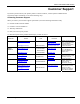
P841C Central-Side VDSL Modem Customer Support If you have questions about your ZyXEL product or desire assistance, contact ZyXEL Communications Corporation offices worldwide, in one of the following ways: Contacting Customer Support When you contact your customer support representative, have the following information ready: ♦ Product model and serial number. ♦ Firmware version information. ♦ Warranty information. ♦ Date you received your product.
P841C Central-Side VDSL Modem Table of Contents Copyright ...................................................................................................................................................................ii ZyXEL Limited Warranty...........................................................................................................................................iii Interference Statements and Warnings .....................................................................................
P841C Central-Side VDSL Modem List of Figures Figure 1-1 Campus Application ..................................................................................................................................................1-2 Figure 2-1 P841C Front Panel.....................................................................................................................................................2-1 Figure 2-2 P841C Back Panel ............................................................................
P841C Central-Side VDSL Modem List of Tables Table 2-1 P841C LED Descriptions............................................................................................................................................ 2-1 Table 2-2 P841C Rear Panel Connectors .................................................................................................................................... 2-2 Table 3-1 P841C Help Commands.....................................................................................
P841C Central-Side VDSL Modem Preface Congratulations on your purchase of the Prestige 841C Central-Side VDSL Modem. This preface introduces you to the Prestige 841C and discusses the organization and conventions of this user’s guide. It also provides information on other related documentation. About VDSL VDSL (Very high bit rate Digital Subscriber Line) is one type of DSL with very high data rates.
P841C Central-Side VDSL Modem Chapter 1 Getting to Know the P841C This chapter describes the key features, benefits and applications of your P841C. The P841C is a VDSL Line Termination (LT) modem that is the perfect partner for the P841 VDSL subscriber modem. It maps traffic from one VDSL (Very high bit rate Digital Subscriber Line) subscriber to one 10/100M Ethernet that connects to a computer or LAN switch. It has built-in POTS/ISDN splitters and a console port for local management. 1.
P841C Central-Side VDSL Modem Figure 1-1 Campus Application 1-2 Getting to Know the P841C
P841C Central-Side VDSL Modem Chapter 2 Hardware Connections This chapter gives a brief introduction to the P841C hardware. 2.1 Front Panel The following figure shows the front panel of the P841C. Figure 2-1 P841C Front Panel 2.1.1 Front Panel LEDs The following table describes the LED indicators on the front panel of the P841C. Table 2-1 P841C LED Descriptions LED COLOR STATUS PWR Green ON The system is turned on. OFF The system is off.
P841C Central-Side VDSL Modem Figure 2-2 P841C Back Panel 2.2.1 Rear Panel Connectors Table 2-2 P841C Rear Panel Connectors CONNECTER POWER 12VDC DESCRIPTION Make sure you are using the correct power source. Connect the female end of the power adapter to the power receptacle on the rear panel of your P841C. Connect the other end of the adapter to a power outlet. LAN 10/100M The Ethernet interface is an RJ-45 connector. Use a crossover Ethernet cable to connect to a hub or WAN switch.
P841C Central-Side VDSL Modem Chapter 3 Configuring the P841C This chapter shows you how to configure and maintain your P841C using the command line interface. 3.
P841C Central-Side VDSL Modem P841C>**** Wrong Password! Figure 3-3 Wrong Password You should change the default password using the passwd command. 3.3 Commands 3.3.1 General Command Conventions References to “LT” and “NT” are common throughout the commands. “LT” means means Line Termination (unit), which is the P841C VDSL central office side modem. “NT” means Network Termination (unit), which is the subscriber’s VDSL modem (P841). 3.3.
P841C Central-Side VDSL Modem ZyXEL recommend you change your password after your very first login. Store your new password in a secure place for later reference in case you forget it. 3.4.2 Exit Command exit Enter this command to log out. You will then have to re-enter your password to log in again. P841C>exit Password: Figure 3-5 Exit Command System Timeout Please note that if there is no activity for longer than five minutes after you log in, your P841C will automatically log you out.
P841C Central-Side VDSL Modem Table 3-1 P841C Help Commands FIELD DESCRIPTION System-related Commands sys Entering this command displays the system status. help or ? Entering this command shows the Help screen displayed exit Enter this command to log out of command mode. passwd Enter this command to change the login password. fwupgrade Enter this command to upgrade the P841C firmware.
P841C Central-Side VDSL Modem Table 3-1 P841C Help Commands FIELD DESCRIPTION enet speed (lt|nt) (speed) Type this command to set the Ethernet port speed of the P841C (you must type “lt”) or P841 (“nt”). P841C speed is displayed if you just type “enet speed”. enet fctrl (lt|nt) [on|off] Type this command to set the Ethernet port full duplex flow control of the P841C (you must type “lt”) or P841 (“nt”). P841C full duplex flow control is displayed if you just type “enet fctrl”.
P841C Central-Side VDSL Modem You MUST NOT abort this operation after XMODEM data transfer begins. Otherwise the device will be damaged. Restart your device before XMODEM transfer begins to quit the upgrade process. Figure 3-9 Upgrade Firmware Last Warning Step 4. Launch your terminal emulation program (see next example). You should have already downloaded the firmware and unzipped it on your computer. The firmware file has a “bin” extension. Begin the file transfer.
P841C Central-Side VDSL Modem Chapter 4 VDSL- Related Commands This chapter shows you how to configure VDSL using Commands. 4.1 Introduction VDSL-related commands supported by the P841C are shown in Table 3-1.The default values for the following VDSL parameters are: Table 4-1 VDSL Default Values VDSL PARAMETER DEFAULT VALUE VDSL Mode 0 = 10BaseS mode VDSL Active On VDSL Upstream Rate 12Mbps VDSL Downstream Rate 12Mbps 4.1.
P841C Central-Side VDSL Modem Table 4-3 VDSL Mode, Frequency Ranges and Rates VDSL MODE FREQ. RANGE (Hz) RATE (Mbps) 10 Base-S Upstream 4.0M 7.9M 1.56 6.25 9.38 12.50 18.75 Downstream 900K 3.0M 4.17 6.25 8.33 12.50 16.67 12.50 16.67 ANSI Mode (ANSI/ETSI Band Plan 998) Upstream 4.0M 5.0M 1.56 3.13 6.25 Downstream 900K 3.0M 4.17 6.25 8.33 ETSI Mode (ETSI Band Plan 997) 4.1.2 Upstream 4.0M 5.0M 1.56 3.13 6.25 Downstream 900K 2.7M 4.17 6.25 9.38 12.
P841C Central-Side VDSL Modem P841C>vdsl downrate vdsl downstream rate: 4166667 bps (0) Figure 4-3 VDSL Downstream Rate Table 4-4 VDSL Rates UPRATE/DOWN RATE UPSTREAM RATE DOWNSTREAM RATE 10BaseS Mode 0 1.56Mbps 4.17Mbps 1 6.25Mbps 6.25Mbps 2 9.38Mbps 8.33Mbps 3 12.50Mbps 12.50Mbps 4 18.75Mbps 16.67Mbps ANSI Mode (ANSI/ETSI Band Plan 998) 0 1.56Mbps 4.17Mbps 1 3.13Mbps 6.25Mbps 2 6.25Mbps 8.33Mbps 3 12.50Mbps 4 16.67Mbps ETSI Mode (ETSI Band Plan 997) 0 1.56Mbps 4.
P841C Central-Side VDSL Modem This command makes the P841C loads new VDSL modem code into the P841C (LT) or P841 (NT). If “LT” is specified, the P841C will load the VDSL modem code into the P841C. If “NT” is specified, the P841C will load the VDSL modem code into the P841. The VDSL connection should automatically reconnect after the new VDSL modem code has been successfully loaded. 4.1.6 VDSL Reset Command vdsl reset This command causes a software reset to the VDSL Chip (local or remote).
P841C Central-Side VDSL Modem Table 4-5 VDSL Status Counters FIELD DESCRIPTION VDSL Parameters: All these fields except for DISC are displayed in hexadecimal format. LINK STAT DISC Modem Code This field displays the link status. The link is up if this field displays 0xac or 0xae; otherwise the link is down. This is a VDSL Disconnect counter. This field displays information about the modem code. VDSL Line Quality Status US This is the VDSL UpStream rate.
P841C Central-Side VDSL Modem 0:Loading Patch to LT............................. P841C>2:State 0 - Initialize 2: Write default parameters to LT 2: Goto State 1 3:State 1 - Wait to connect to default rate 17: Default rate connected (15230 ms) 17: VDSL:US 1.56Mbps SNR 34.08dB DS 4.17Mbps SNR 43.08dB 18: VDSL:US PSD -55.69dBm/Hz(946) DS PSD -57.
P841C Central-Side VDSL Modem This command displays your P841C settings as shown in the next example. P841C>vdsl show vdsl mode: 10BaseS(0) vdsl Active flag: on vdsl Max. upstream rate: 1562500 bps (0) vdsl Max.
P841C Central-Side VDSL Modem FIELD DESCRIPTION EXAMPLE vdsl auto upgrade NT EEPROM flag This field shows the VDSL auto upgrade status (“on” or “off”). When auto upgrade is on, the P841C will check the subscriber’s modem VDSL version and automatically upgrade it if it is an earlier version than the P841C’s. off enet monitor flag This field shows the Ethernet monitor flag status (“on” or “off”).
P841C Central-Side VDSL Modem Chapter 5 Ethernet-related Commands This chapter shows you how to configure Ethernet. 5.1 Introduction The P841C has one 10/100Mbps auto-sensing Ethernet port. There are two factors related to Ethernet: speed and duplex mode. In 10/100Mbps Fast Ethernet, the speed can be 10Mbps or 100Mbps and the duplex mode can be half duplex or full duplex.
P841C Central-Side VDSL Modem Type this command to display P841C and the subscriber’s VDSL modem’s Ethernet statistics (if link is up).
P841C Central-Side VDSL Modem 5.1.2 Enet Clear Command enet clear Type this command to clear P841C and the subscriber’s VDSL modem’s Ethernet statistics (if link is up). 5.1.3 Enet Speed (lt|nt) (speed) Command enet speed (lt|nt) (speed) Type this command to set the Ethernet port speed of the P841C (with “lt”) or P841 (with “nt”). P841C speed is displayed if you just type “enet speed”. P841C>enet speed enet speed(LT): Auto Figure 5-2 Ethernet Speed Speed index number 5.1.
P841C Central-Side VDSL Modem When this flag is on this command automatically displays the P841C (and the subscriber’s VDSL modem’s Ethernet statistics if the link is up) every five seconds. Enter the command without “on” or “off” to just show the Ethernet monitor status.
P841C Central-Side VDSL Modem Chapter 6 Troubleshooting This chapter covers potential problems and possible remedies. After each problem description, some steps are provided to help you diagnose and solve the problem. 6.1 VDSL LED The VDSL LED is not on. Table 6-1 Troubleshooting the VDSL LED STEPS CORRECTIVE ACTION 1 Disconnect the phone wire coming from the VDSL port of the P841C and connect the subscriber’s VDSL modem or router directly to the VDSL port of the P841C using a different telephone wire.
P841C Central-Side VDSL Modem 6.3 Intermittent VDSL LED A VDSL LED turns on and off intermittently. Table 6-3 Troubleshooting a Non-Constant VDSL LED STEPS 1 CORRECTIVE ACTION Disconnect the phone wire coming from the VDSL port of the P841C and connect the subscriber’s VDSL modem or router directly to the VDSL port of the P841C using a different telephone wire. If the VDSL LED stays on, check for a problem with the building’s phone wire.
P841C Central-Side VDSL Modem Table 6-6 Troubleshooting Connecting to an Ethernet Switch STEPS CORRECTIVE ACTION Speed: Auto Duplex: Auto Flow control: On for full duplex and off for half-duplex If the P841C’s auto-negotiation is turned off, an Ethernet port uses the pre-configured speed and duplex mode when making a connection, thus requiring you to make sure that the settings of the switch Ethernet port are in the same order to connect.
P841C Central-Side VDSL Modem Power Adapter Specifications NORTH AMERICA AC Power Adapter model AD48-1201200DUY AC Power Adapter model DV-121A2-5720 Input power: AC120Volts/60Hz/0.25A Input power: AC120Volts/60Hz/27VA Output power: DC12Volts/1.2A Output power: DC12Volts/1.2A Power consumption: 6 W Power consumption: 6 W Safety standards: UL, CUL (UL 1950, CSA C22.2 No.234-M90) Safety standards: UL, CUL (UL 1310, CSA C22.2 No.
P841C Central-Side VDSL Modem Index 1 10 Base-S .................................................4-8 10Base-S ...........................................4-7, 4-9 10Base-S Mode ........................................1-1 A ALGM_ERR ............................................5-2 ANSI Mode ..............................................1-1 ANSI/ETSI Plan 998................................4-8 B DISC ...................................................... 4-11 Disclaimer .......................................
P841C Central-Side VDSL Modem I POWER..................................................4-11 Intermittent VDSL LED ...........................6-2 Power Adapter ............................................ A Introducing the SMT ................................3-1 PSD ........................................................4-11 L PWR .........................................................2-1 R LAN 10/100M ..........................................2-2 LATE_COL ........................................
P841C Central-Side VDSL Modem TXBCNT..................................................5-2 vdsl mode ................................ 3-4, 4-7, 4-13 TXPAUS...................................................5-2 VDSL Mode ......................................4-7, 4-8 TXPWR.................................................. 4-11 VDSL Modes ........................................... 1-1 U US........................................................... 4-11 V VDSL ...........................................