P-2900-4HB Cable Router Default Login Details IP Address Password 192.168.1.1 1234 Firmware Version 3.40 www.zyxel.com Edition 1, 3/2009 www.zyxel.
About This User's Guide About This User's Guide Intended Audience This manual is intended for people who want to configure the ZyXEL Device using the web configurator. You should have at least a basic knowledge of TCP/IP networking concepts and topology. Related Documentation • Quick Start Guide The Quick Start Guide is designed to help you get up and running right away. It contains information on setting up your network and configuring for Internet access.
About This User's Guide • Date that you received your device. • Brief description of the problem and the steps you took to solve it.
Document Conventions Document Conventions Warnings and Notes These are how warnings and notes are shown in this User’s Guide. Warnings tell you about things that could harm you or your device. Note: Notes tell you other important information (for example, other things you may need to configure or helpful tips) or recommendations. Syntax Conventions • The P-2900-4HB may be referred to as the “ZyXEL Device”, the “device” or the “system” in this User’s Guide.
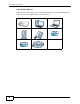
Document Conventions Icons Used in Figures Figures in this User’s Guide may use the following generic icons. The ZyXEL Device icon is not an exact representation of your device.
Safety Warnings Safety Warnings • Use only No. 26 AWG (American Wire Gauge) or larger telecommunication line cord. • Do NOT use this product near water, for example, in a wet basement or near a swimming pool. • Do NOT expose your device to dampness, dust or corrosive liquids. • Do NOT store things on the device. • Do NOT install, use, or service this device during a thunderstorm. There is a remote risk of electric shock from lightning. • Connect ONLY suitable accessories to the device.
Safety Warnings 8 P-2900-4HB User’s Guide
Contents Overview Contents Overview Introduction and Configuration ............................................................................................ 15 Getting To Know Your ZyXEL Device ........................................................................................ 17 Introducing the Web Configurator .............................................................................................. 21 Status ....................................................................................
Contents Overview 10 P-2900-4HB User’s Guide
Table of Contents Table of Contents About This User's Guide .......................................................................................................... 3 Document Conventions............................................................................................................ 5 Safety Warnings........................................................................................................................ 7 Contents Overview .......................................................
Table of Contents Chapter 4 Tutorials ................................................................................................................................... 39 4.1 Overview .............................................................................................................................. 39 4.2 Access the ZyXEL Device Using DDNS .............................................................................. 39 4.2.1 Registering a DDNS Account on www.dyndns.org .......................
Table of Contents 6.3.3 How NAT Works ......................................................................................................... 64 6.3.4 NAT Mapping Types ................................................................................................... 65 Chapter 7 Dynamic DNS Setup ............................................................................................................... 67 7.1 Overview ................................................................................
Table of Contents 11.3 The DHCP Table Screen ................................................................................................... 83 11.4 The Diagnostics Screen ..................................................................................................... 85 Part IV: Product Specification, Appendices and Index ...................... 87 Chapter 12 Troubleshooting......................................................................................................................
P ART I Introduction and Configuration Getting To Know Your ZyXEL Device (17) Introducing the Web Configurator (21) Status (27) 15
CHAPTER 1 Getting To Know Your ZyXEL Device This chapter describes the key features and applications of your ZyXEL Device. 1.1 Overview The ZyXEL Device is an embedded Multimedia Terminal Adapter (eMTA) device built with two components: a DOCSIS 2.0 cable modem component for data transfer and a PacketCable 1.5 MTA component for voice traffic. This means it can provide high-speed Internet access as well as cost-effective, standard telephone voice and fax/modem services through your cable service provider.
Chapter 1 Getting To Know Your ZyXEL Device 1.3 LEDs (Lights) The following figure displays the labels of the LED. Figure 2 Front Panel LEDs The following table describes the LEDs. Table 1 Front Panel LEDs LED COLOR STATUS DESCRIPTION PWR Green On The ZyXEL Device is receiving AC power. Blinking The ZyXEL Device is receiving sufficient power from the battery. Off The ZyXEL Device is not receiving power or it is starting up. On The ZyXEL Device has successfully found a downstream channel.
Chapter 1 Getting To Know Your ZyXEL Device Table 1 Front Panel LEDs (continued) LED COLOR STATUS DESCRIPTION USB Green On A computeris connected to the USB port on the ZyXEL Device. See Section 1.4 on page 19 for more information about the USB port. Blinking The ZyXEL Device is sending/receiving data via the USB port. Off The USB port is not connected. On The ZyXEL Device has successfully registered to an IP telephone network.
Chapter 1 Getting To Know Your ZyXEL Device Note: When the battery is in use, you can only make VoIP calls. Ethernet connections will not function. Note: Battery packs are sold separately.
CHAPTER 2 Introducing the Web Configurator This chapter describes how to access the ZyXEL Device web configurator and provides an overview of its screens. 2.1 Overview The web configurator is an HTML-based management interface that allows easy setup and management via an Internet browser. Use Internet Explorer 6.0 and later or Netscape Navigator 7.0 and later versions. The recommended screen resolution is 1024 by 768 pixels.
Chapter 2 Introducing the Web Configurator 2.2 Accessing the Web Configurator Follow the steps below to log into the Web Configurator. 1 Launch your web browser. Enter “192.168.1.1” as the web site address. Figure 3 Web browser URL screen. 2 A login screen displays. Enter the password (“1234” by default) and click Login.
Chapter 2 Introducing the Web Configurator 2.2.1 Resetting the ZyXEL Device If you forget your password or cannot access the web configurator, you will need to use the RESET button at the back of the ZyXEL Device to reload the factorydefault configuration file. This means that you will lose all configurations that you had previously and the password will be reset to “1234”. 2.2.1.1 Using the RESET Button 1 Make sure the PWR LED is on (not blinking).
Chapter 2 Introducing the Web Configurator Following table lists the menu screens. Table 2 Web Configurator Screens Summary LINK SUB-LINK FUNCTION Status System Status Use this screen to view firmware and system related information. CableModem Status Use this screen to view information about the cable modem, upstream and downstream channels. MTA Status Use this screen to view information about MTA and status about the VoIP ports.
Chapter 2 Introducing the Web Configurator want to change to a new password again, then click Password in the Site Map screen to display the screen as shown next. Figure 7 Password The following table describes the fields in this screen. Table 3 Password LABEL DESCRIPTION Old Password Type the default password or the existing password you use to access the system in this field. New Password Type the new password in this field. Retype to Confirm Type the new password again in this field.
Chapter 2 Introducing the Web Configurator 26 P-2900-4HB User’s Guide
CHAPTER 3 Status 3.1 Overview This chapter describes the status screens you can display the ZyXEL Device’s firmware and system information. 3.2 What You Can Do in the Status Screens • Use the System Status screen (see Section 3.3 on page 30) to view firmware, LAN and WAN information. • Use the Cable Modem Status screen (see Section 3.4 on page 32) to view status information about the cable modem, upstream and downstream channels. • Use the MTA Status screen (see Section 3.
Chapter 3 Status cable modem part is used for data traffic, and the MTA part is used for VoIP traffic. The following figure illustrates how it works. Figure 8 CM and MTA ZyXEL Device (Embedded MTA) Cable Modem MTA CM Configuration File CM IP Address CM MAC Address MTA Configuration File MTA IP Address MTA MAC Address Data VoIP Management IP Addresses The ZyXEL Device automatically gets one CM and one MTA management IP addresses from the cable service provider when the cable connection is established.
Chapter 3 Status illustrated in the following figure, it requires several steps to complete the initiation process. Figure 9 Cable Network Initiation Process Lock a DS channel Lock an US channel CM Auto-Provisioning MTA Auto-Provisioning • Search and lock a downstream channel. • Search and lock an upstream channel. • Auto-provisioning of the cable modem settings. • Auto-provisioning of the MTA settings. See Section on page 32 for more details about the provisioning process.
Chapter 3 Status 3.3 The System Status Screen Click Status > System Status to open the following screen. Check these fields when there is a problem with the network connection. Figure 10 Status > System Status The following table describes the labels in this screen. Table 4 Status > System Status LABEL DESCRIPTION System Status System Name This is the ZyXEL Device’s name. It is for identification purpose. ZyNOS F/W Version This is the current version of the firmware the device uses.
Chapter 3 Status Table 4 Status > System Status (continued) LABEL DESCRIPTION IP Address This is the static IP address you configured in the Advanced Setup > Static IP screen. Normally, this is a public IP address used to communicate with the Internet. The IP address appears as 0.0.0.0 if you did not configure a static IP address. IP Subnet Mask This is the subnet mask of the static IP address.
Chapter 3 Status 3.4 The Cable Modem Status Screen This section describes the information in the Cable Modem Status screen. 3.4.1 What You Need to Know About Cable Modem Status Downstream/Upstream Channels In order to establish a successful connection with the cable provider’s network, the ZyXEL Device must first find and lock onto two frequencies for communication with the cable operator’s network. A frequency is also called a channel.
Chapter 3 Status 3.4.2 Viewing the Cable Modem Status Screen Click Status > CM Status or Status > CableModem Status to open the following screen.
Chapter 3 Status The following table describes the labels in this screen. Table 5 Status > CM Status or Status > CableModem Status LABEL DESCRIPTION Startup Procedure To establish a successful connection to the cable provider’s network, the ZyXEL Device must go through a series of well-defined initialization steps. Boot State This is the provision status of the cable modem. • • • • • • • • • Configuration File This is the name of the configuration file on the ZyXEL Device.
Chapter 3 Status Table 5 Status > CM Status or Status > CableModem Status (continued) LABEL DESCRIPTION Lock Status This indicates whether ZyXEL Device has found a downstream channel. The ZyXEL Device is either Locked or Not Locked on to the channel advertised by the CMTS. Modulation This is the method used to encode transmission information, similar to FM or AM on your radio. The ZyXEL Device supports 256 QAM or 64 QAM (Quadrature Amplitude Modulation) for the downstream channel.
Chapter 3 Status 3.5 The MTA Status Screen The Multimedia Terminal Adapter (MTA) supports conversion between analog telephone signals and IP data packets, providing Voice over IP (VoIP) interfaces for analog telephones. Use the MTA Status screen to view information about the MTA. Click Status > MTA Status to display the screen as shown. Figure 13 Status > MTA Status The following table describes the labels in this screen.
Chapter 3 Status Table 6 Status > MTA Status (continued) LABEL DESCRIPTION Gateway IP Address This is the IP address of the default gateway, if applicable. TFTP IP Address This is the IP address of TFTP. Voice Information Line 1-4 P-2900-4HB User’s Guide This field shows the status information about the VoIP ports.
Chapter 3 Status 38 P-2900-4HB User’s Guide
CHAPTER 4 Tutorials 4.1 Overview This chapter shows you how to use the ZyXEL Device’s various features. • Access the ZyXEL Device Using DDNS, see page 39 • Multiple WAN Configuration, see page 41 4.2 Access the ZyXEL Device Using DDNS If you connect your ZyXEL Device to the Internet and it uses a dynamic WAN IP address, it is inconvenient for you to manage the device from the Internet. The ZyXEL Device’s WAN IP address changes dynamically.
Chapter 4 Tutorials 4.2.1 Registering a DDNS Account on www.dyndns.org 1 Open a browser and type http://www.dyndns.org. 2 Apply for a user account. This tutorial uses UserName1 and 12345 as the username and password. 3 Log into www.dyndns.org using your account. 4 Add a new DDNS host name. This tutorial uses the following settings as an example. • Hostname: zyxelrouter.dyndns.org • Service Type: Host with IP address • IP Address: Enter the WAN IP address that your ZyXEL Device is currently using.
Chapter 4 Tutorials Click Apply. 2d 4.2.3 Testing the DDNS Setting Now you should be able to access the ZyXEL Device from the Internet. To test this: 1 Open a web browser on the computer (using the IP address a.b.c.d) that is connected to the Internet. 2 Type http://zyxelrouter.dyndns.org and press [Enter]. 3 The ZyXEL Device’s login page should appear. You can then log into the ZyXEL Device and manage it. 4.
Chapter 4 Tutorials This tutorial uses the following example settings: Table 7 IP Settings in this Tutorial DEVICE / COMPUTER IP ADDRESS Static IP 1 1.1.1.1/24 Static IP 2 2.2.2.1/24 Static IP 3 3.3.3.1/24 LAN IPs Management IP: 192.168.1.1/24 DHCP Type: Server DHCP IP Range: 192.168.1.33~192.168.1.64 A’s IP 1.1.1.5/24 (IP-1), gateway: 1.1.1.1 B’s IP 2.2.2.5/24 (IP-2), gateway: 2.2.2.
Chapter 4 Tutorials 3 Log into the ZyXEL Device’s Web Configurator. Configure the Advanced Setup > LAN screen as shown next. Click Apply. 4 Enable DHCP client on computers C1 and C2 by selecting Obtain an IP address automatically in the network settings. Connect them to the ZyXEL Device’s LAN through a switch. Each of them should get an IP address respectively. 4.3.2 Configuring Static IP Addresses Use this section to configure two static IP addresses for servers A and B.
Chapter 4 Tutorials 1 Configure the Advanced > Static IP screen as shown. Click Apply. 2 Ping A and B in the Maintenance > Diagnostic screen to test the connectivity. You should get A’s and B’s responses. If they fail, make sure the network is correctly connected and if each server has a firewall that they allow ping packets from the ZyXEL Device. An example is shown next. 4.3.
Chapter 4 Tutorials 1 Select Full Feature and click Apply in the Advanced Setup > NAT screen. 2 Click the Edit Details link in the NAT-Mode screen above. The NAT - Address Mapping Rules screen appears as shown next. 3 Click the Rule 1 link. 4 Configure the settings as shown next. Then click Apply.
Chapter 4 Tutorials 5 Computer C1 should be able to connect to the Internet. 4.3.4 Access the Web/FTP Services from the Internet Use a computer on the Internet to access http://1.1.1.5 and ftp://2.2.2.5. You should be able to access a web page on A and the FTP login screen on B.
P ART II Advanced Setup LAN Setup (49) Network Address Translation (NAT) Screens (59) Dynamic DNS Setup (67) Remote Management Configuration (71) Logs (75) 47
CHAPTER 5 LAN Setup 5.1 Overview A Local Area Network (LAN) is a shared communication system to which many networking devices are connected. It is limited to the immediate area, usually the same building or floor of a building. Use the LAN screens to help you configure a LAN DHCP server and manage IP addresses. LAN 5.1.1 What You Can Do in the LAN Screens • Use the LAN Setup screen (Section 5.2 on page 51) to configure the DHCP settings, and set the LAN IP address and subnet mask of your ZyXEL Device.
Chapter 5 LAN Setup Subnet Mask Subnet masks determine the maximum number of possible hosts on a network. You can also use subnet masks to divide one network into multiple sub-networks. DHCP A DHCP (Dynamic Host Configuration Protocol) server can assign your ZyXEL Device an IP address, subnet mask, DNS and other routing information when it's turned on. RIP RIP (Routing Information Protocol) allows a router to exchange routing information with other routers.
Chapter 5 LAN Setup 5.2 The LAN Setup Screen Click Advanced Setup > LAN > LAN Setup to open the LAN Setup screen. Figure 15 Advanced Setup > LAN > LAN Setup The following table describes the fields in this screen. Table 8 Advanced Setup > LAN > LAN Setup LABEL DESCRIPTION DHCP DHCP If set to Server, your ZyXEL Device can assign IP addresses, an IP default gateway and DNS servers to Windows 95, Windows NT and other systems that support the DHCP client. If set to None, the DHCP server will be disabled.
Chapter 5 LAN Setup Table 8 Advanced Setup > LAN > LAN Setup (continued) LABEL DESCRIPTION Primary DNS Server Enter the IP addresses of the DNS servers. The DNS servers are passed to the DHCP clients along with the IP address and the subnet mask. Secondary DNS Server As above. Remote DHCP Server If Relay is selected in the DHCP field above then enter the IP address of the actual remote DHCP server here.
Chapter 5 LAN Setup lease expires. If you want the computer to always receive the same IP address from the DHCP server, then configure a static DHCP IP address here. Figure 16 Advanced Setup > LAN > Static DHCP The following table describes the fields in this screen. Table 9 Advanced Setup > LAN > Static DHCP LABEL DESCRIPTION # This is the index number for the entries in this table. MAC Address Type the MAC address of the computer to which you want to assign a specific DHCP IP address.
Chapter 5 LAN Setup 5.4 LAN Technical Reference This section provides some technical background information about the topics covered in this chapter. 5.4.1 DHCP Setup DHCP (Dynamic Host Configuration Protocol, RFC 2131 and RFC 2132) allows individual clients to obtain TCP/IP configuration at start-up from a server. You can configure the ZyXEL Device as a DHCP server or disable it. When configured as a server, the ZyXEL Device provides the TCP/IP configuration for the clients.
Chapter 5 LAN Setup the connection is established. If this were the case, it is recommended that you select a network number from 192.168.0.0 to 192.168.255.0 and you must enable the Network Address Translation (NAT) feature of the ZyXEL Device. The Internet Assigned Number Authority (IANA) reserved this block of addresses specifically for private use; please do not use any other number unless you are told otherwise. Let's say you select 192.168.1.
Chapter 5 LAN Setup 5.4.4 RIP Setup RIP Directions The sending and receiving of RIP packets can occur in the following ways: • Both - the ZyXEL Device will broadcast its routing table periodically and incorporate the RIP information that it receives. • In Only - the ZyXEL Device will not send any RIP packets but will accept all RIP packets received. • Out Only - the ZyXEL Device will send out RIP packets but will not accept any RIP packets received.
Chapter 5 LAN Setup to gather group membership. After that, the ZyXEL Device periodically updates this information. IP multicasting can be enabled/disabled on the ZyXEL Device LAN and/or WAN interfaces in the web configurator (LAN; WAN). Select None to disable IP multicasting on these interfaces.
Chapter 5 LAN Setup 58 P-2900-4HB User’s Guide
CHAPTER 6 Network Address Translation (NAT) Screens 6.1 Overview This chapter discusses how to configure NAT on the ZyXEL Device. NAT (Network Address Translation - NAT, RFC 1631) is the translation of the IP address of a host in a packet, for example, the source address of an outgoing packet, used within one network to a different IP address known within another network. 6.1.1 What You Can Do in the NAT Screen Use the NAT Mode screen (Section 6.
Chapter 6 Network Address Translation (NAT) Screens NAT translates the destination address (the inside global address) back to the inside local address before forwarding it to the original inside host. Finding Out More See Section 6.3 on page 63 for technical background information on NAT. 6.2 The NAT Mode Screen You must create a firewall rule in addition to setting up NAT, to allow traffic from the WAN to be forwarded through the ZyXEL Device. Click Advanced Setup > NAT to open the following screen.
Chapter 6 Network Address Translation (NAT) Screens rule 4, rules 5 to 7 will be pushed up by 1 rule, so old rules 5, 6 and 7 become new rules 4, 5 and 6. Click Advanced Setup > NAT, select Full Feature and click Edit Details to open the following screen. Use this screen to change your ZyXEL Device’s address mapping settings. Figure 18 Address Mapping Rules The following table describes the fields in this screen.
Chapter 6 Network Address Translation (NAT) Screens 6.2.2 Editing an Address Mapping Rule Use this screen to edit an address mapping rule. Click the rule’s link in the NAT Address Mapping Rules screen to display the screen shown next. Figure 19 Edit Address Mapping Rule The following table describes the fields in this screen. Table 12 Edit Address Mapping Rule LABEL DESCRIPTION Type Choose the port mapping type from one of the following.
Chapter 6 Network Address Translation (NAT) Screens Table 12 Edit Address Mapping Rule (continued) LABEL DESCRIPTION Apply Click Apply to save your changes back to the ZyXEL Device. Cancel Click Cancel to return to the previously saved settings. Delete Click Delete to exit this screen without saving. 6.3 NAT Technical Reference This section provides some technical background information about the topics covered in this chapter. 6.3.
Chapter 6 Network Address Translation (NAT) Screens 6.3.2 What NAT Does In the simplest form, NAT changes the source IP address in a packet received from a subscriber (the inside local address) to another (the inside global address) before forwarding the packet to the WAN side. When the response comes back, NAT translates the destination address (the inside global address) back to the inside local address before forwarding it to the original inside host.
Chapter 6 Network Address Translation (NAT) Screens 6.3.4 NAT Mapping Types NAT supports five types of IP/port mapping. They are: • One to One: In One-to-One mode, the ZyXEL Device maps one local IP address to one global IP address. • Many to One: In Many-to-One mode, the ZyXEL Device maps multiple local IP addresses to one global IP address. • Server: This type allows you to specify inside servers of different services behind the NAT to be accessible to the outside world.
Chapter 6 Network Address Translation (NAT) Screens 66 P-2900-4HB User’s Guide
CHAPTER 7 Dynamic DNS Setup 7.1 Overview Dynamic DNS allows you to update your current dynamic IP address with one or many dynamic DNS services so that anyone can contact you (in NetMeeting, CUSeeMe, etc.). You can also access your FTP server or Web site on your own computer using a domain name (for instance myhost.dhs.org, where myhost is a name of your choice) that will never change instead of using an IP address that changes each time you reconnect.
Chapter 7 Dynamic DNS Setup 7.2 The Dynamic DNS Screen To change your ZyXEL Device’s DDNS, click Advanced Setup > Dynamic DNS. The screen appears as shown. Figure 21 Advanced Setup > Dynamic DNS The following table describes the fields in this screen. Table 15 Advanced Setup > Dynamic DNS LABEL DESCRIPTION Active Select this check box to use dynamic DNS. Service Provider This is the name of your Dynamic DNS service provider.
CHAPTER 8 Static IP 8.1 Overview Use the Static IP screen (see Section 8.2 on page 69) to assign static IP addresses and configure the RIPv2 settings. See the Section 4.3 on page 41 for an application example of how you can use static IP addresses. 8.2 The Static IP Screen Click Advanced Setup > Static IP to open the following screen. Use this screen to configure the static WAN IP addresses.
Chapter 8 Static IP The following table describes the fields in this screen. Table 16 Advanced Setup > Static IP LABEL DESCRIPTION Static IP Active Static IP 1-3 Select this to activate the static IP feature. IP Enter the IP address in this field. Subnet Mask Enter the subnet mask in this field. RIPv2 70 Enable Select this to activate RIP. ID (1-255) Enter the ID number obtained from the router you want to exchange information.
CHAPTER 9 Remote Management Configuration 9.1 Overview Remote management allows you to determine which services/protocols can access which ZyXEL Device interface (if any) from which computers. The following figure shows remote management of the ZyXEL Device coming in from the WAN. Figure 23 Remote Management From the WAN LAN WAN HTTP Telnet Note: When you configure remote management to allow management from the WAN, you still need to configure a firewall rule to allow access.
Chapter 9 Remote Management Configuration You may only have one remote management session running at a time. The ZyXEL Device automatically disconnects a remote management session of lower priority when another remote management session of higher priority starts. The priorities for the different types of remote management sessions are as follows. 1 Telnet 2 HTTP Finding Out More See Section 9.3 on page 74 for technical background information on remote management configuration. 9.1.
Chapter 9 Remote Management Configuration The following table describes the fields in this screen. Table 17 Advanced Setup > Remote Management LABEL DESCRIPTION Server Type Each of these labels denotes a service that you may use to remotely manage the ZyXEL Device. Access Status Select the access interface. Choices are All, LAN Only, WAN Only and Disable. Port This field shows the port number for the remote management service.
Chapter 9 Remote Management Configuration 9.3 Remote Management Technical Reference This section provides some technical background information about the topics covered in this chapter. 9.3.1 Remote Management Limitations Remote management does not work when: • You have not enabled that service on the interface in the corresponding remote management screen. • You have disabled that service in one of the remote management screens.
CHAPTER 10 Logs 10.1 Overview This chapter contains information about configuring general log settings and viewing the ZyXEL Device’s logs. Refer to the appendix for example log message explanations. The web configurator allows you to choose which categories of events and/or alerts to have the ZyXEL Device log and then display the logs or have the ZyXEL Device send them to an administrator (as e-mail) or to a syslog server. 10.1.
Chapter 10 Logs 10.2 The Log Settings Screen Use the Log Settings screen to configure to where the ZyXEL Device is to send logs; the schedule for when the ZyXEL Device is to send the logs and which logs and/or immediate alerts the ZyXEL Device is to record. To change your ZyXEL Device’s log settings, click Advanced Setup > Logs > Log Settings to open the following screen. Alerts are e-mailed as soon as they happen. Logs may be e-mailed as soon as the log is full.
Chapter 10 Logs The following table describes the fields in this screen. Table 18 Advanced Setup > Logs > Log Settings LABEL DESCRIPTION Address Info Mail Server Enter the server name or the IP address of the mail server for the e-mail addresses specified below. If this field is left blank, logs and alert messages will not be sent via e-mail. Mail Subject Type a title that you want to be in the subject line of the log e-mail message that the ZyXEL Device sends.
Chapter 10 Logs 10.3 The View Logs Screen Click Advanced Setup > Logs > View Logs to open the screen. Use the View Logs screen to see the logs for the categories that you selected in the Log Settings screen (see Section 10.2 on page 76). Entries in red indicate alerts. The log wraps around and deletes the old entries after it fills. Click a column heading to sort the entries. A triangle indicates ascending or descending sort order.
Chapter 10 Logs • You may edit the subject title. • "End of Log" message shows that a complete log has been sent. Figure 28 E-mail Log Example Subject: Firewall Alert From ZyXEL Device Time Format Date: Day-Month-Year Fri, 07 Apr 2000 10:05:42 From: user@zyxel.com Time Format To: Month-Day-Year user@zyxel.com 1|Apr 7 00 |From:192.168.1.1 To:192.168.1.255 |default policy |forward | 09:54:03 |UDP src port:00520 dest port:00520 |<1,00> | 2|Apr 7 00 |From:192.168.1.131 To:192.168.1.
Chapter 10 Logs 80 P-2900-4HB User’s Guide
P ART III Maintenance and Troubleshooting Maintenance (83) Troubleshooting (89) 81
CHAPTER 11 Maintenance 11.1 Overview This chapter discusses how to view the DHCP client and system information. 11.2 What You Can Do in this Chapter • Use the DHCP Table screen (Section 11.3 on page 83) to show current DHCP Client information (including IP Address, Host Name and MAC Address) of all network clients using the DHCP server. • Use the Diagnostic screens (Section 11.4 on page 85) to display information to help you identify problems with the ZyXEL Device. 11.
Chapter 11 Maintenance information (including IP Address, Host Name and MAC Address) of all network computers using the DHCP server. Figure 29 Maintenance > DHCP Table The following table describes the fields in this screen. Table 20 Maintenance > DHCP Table LABEL DESCRIPTION Host Name This is the name of the host computer. IP Address This field displays the IP address relative to the Host Name field.
Chapter 11 Maintenance 11.4 The Diagnostics Screen Use the Diagnostics screen to ping a device to test the connection. Click Maintenance > Diagnostic to display the screen. Figure 30 Maintenance > Diagnostic The following table describes the labels in this screen. Table 21 Maintenance > Diagnostic LABEL DESCRIPTION Info This read-only text box displays the ping test results. TCP/IP Address Ping Type the IP address of a device that you want to ping in order to test a connection.
Chapter 11 Maintenance 86 P-2900-4HB User’s Guide
P ART IV Product Specification, Appendices and Index Product Specifications (91) Setting up Your Computer’s IP Address (97) Common Services (115) Legal Information (119) Index (123) 87
CHAPTER 12 Troubleshooting 12.1 Overview This chapter offers some suggestions for solving problems you might encounter. None of the LEDs turn on when you turn the power on. • Make sure that you use the included power adapter to connect to the ZyXEL Device and that it is plugged into an appropriate power source. • Check all cable connections. If the LEDs still do not turn on, you may have a hardware problem. In this case, you should contact your local vendor. Cannot access the Internet.
Chapter 12 Troubleshooting • If you want your computer to get a dynamic IP address assigned by a DHCP server provided by your cable service provider, make sure your computer is able to receive a dynamic IP address. You have to also disable the DHCP Server function on the ZyXEL Device (select None in the DHCP field in the Advanced Setup > LAN > LAN Setup screen, see Section 5.2 on page 51) The USB LED is off. • Check the USB cable connection. Unplug and plug in the USB cable.
APPENDIX A Product Specifications See also the Introduction chapter for a general overview of the key features. General ZyXEL Device Specifications The following tables summarize the ZyXEL Device’s hardware and firmware features. Table 22 Hardware Specifications SPECIFICATION DESCRIPTION Dimensions 243.36 mm (W) x 160.98mm (D) x 40.
Appendix A Product Specifications Table 22 Hardware Specifications SPECIFICATION DESCRIPTION Maximum Data rate 30 Mbps for 64 QAM Symbol Rates 5.057 Msym/s for 64 QAM 40 Mbps for 256 QAM 5.361 Msym/s for 256 QAM Operating Level -15 to +15 dBmV UPSTREAM CHANNEL Frequency Range 5 to 42 Mhz Bandwidth 200 Khz/400 Khz/800 Khz 1.6 Mhz/3.2 Mhz/6.
Appendix A Product Specifications Table 23 Firmware Features FEATURE DESCRIPTION Network Address Translation (NAT) Each computer on your network must have its own unique IP address. Use NAT to convert your public IP address(es) to multiple private IP addresses for the computers on your network. Port Forwarding If you have a server (mail or web server for example) on your network, you can use this feature to let people access it from the Internet.
Appendix A Product Specifications Table 23 Firmware Features FEATURE DESCRIPTION Cable Modem Standards DOCSIS 2.0 compliant DOCSIS 1.1/1.0 backward compatible Packet Cable 1.5/1.
Appendix A Product Specifications 3 Do not insert the screws all the way into the wall. Leave a small gap of about 0.5 cm between the heads of the screws and the wall. 4 Make sure the screws are snugly fastened to the wall. They need to hold the weight of the ZyXEL Device with the connection cables. 5 Align the holes on the back of the ZyXEL Device with the screws on the wall. Hang the ZyXEL Device on the screws.
Appendix A Product Specifications 96 P-2900-4HB User’s Guide
APPENDIX B Setting up Your Computer’s IP Address All computers must have a 10M or 100M Ethernet adapter card and TCP/IP installed. Windows 95/98/Me/NT/2000/XP, Macintosh OS 7 and later operating systems and all versions of UNIX/LINUX include the software components you need to install and use TCP/IP on your computer. Windows 3.1 requires the purchase of a thirdparty TCP/IP application package.
Appendix B Setting up Your Computer’s IP Address Windows 95/98/Me Click Start, Settings, Control Panel and double-click the Network icon to open the Network window. Figure 33 WIndows 95/98/Me: Network: Configuration Installing Components The Network window Configuration tab displays a list of installed components. You need a network adapter, the TCP/IP protocol and Client for Microsoft Networks. If you need the adapter: 1 In the Network window, click Add. 2 Select Adapter and then click Add.
Appendix B Setting up Your Computer’s IP Address 3 Select Microsoft from the list of manufacturers. 4 Select TCP/IP from the list of network protocols and then click OK. If you need Client for Microsoft Networks: 1 Click Add. 2 Select Client and then click Add. 3 Select Microsoft from the list of manufacturers. 4 Select Client for Microsoft Networks from the list of network clients and then click OK. 5 Restart your computer so the changes you made take effect.
Appendix B Setting up Your Computer’s IP Address 3 Click the DNS Configuration tab. • If you do not know your DNS information, select Disable DNS. • If you know your DNS information, select Enable DNS and type the information in the fields below (you may not need to fill them all in). Figure 35 Windows 95/98/Me: TCP/IP Properties: DNS Configuration 4 Click the Gateway tab. • If you do not know your gateway’s IP address, remove previously installed gateways.
Appendix B Setting up Your Computer’s IP Address Windows 2000/NT/XP The following example figures use the default Windows XP GUI theme. 1 Click start (Start in Windows 2000/NT), Settings, Control Panel. Figure 36 Windows XP: Start Menu 2 In the Control Panel, double-click Network Connections (Network and Dialup Connections in Windows 2000/NT).
Appendix B Setting up Your Computer’s IP Address 3 Right-click Local Area Connection and then click Properties. Figure 38 Windows XP: Control Panel: Network Connections: Properties 4 Select Internet Protocol (TCP/IP) (under the General tab in Win XP) and then click Properties. Figure 39 Windows XP: Local Area Connection Properties 5 102 The Internet Protocol TCP/IP Properties window opens (the General tab in Windows XP).
Appendix B Setting up Your Computer’s IP Address • If you have a dynamic IP address click Obtain an IP address automatically. • If you have a static IP address click Use the following IP Address and fill in the IP address, Subnet mask, and Default gateway fields. • Click Advanced. Figure 40 Windows XP: Internet Protocol (TCP/IP) Properties 6 If you do not know your gateway's IP address, remove any previously installed gateways in the IP Settings tab and click OK.
Appendix B Setting up Your Computer’s IP Address • Click OK when finished. Figure 41 Windows XP: Advanced TCP/IP Properties 7 In the Internet Protocol TCP/IP Properties window (the General tab in Windows XP): • Click Obtain DNS server address automatically if you do not know your DNS server IP address(es). • If you know your DNS server IP address(es), click Use the following DNS server addresses, and type them in the Preferred DNS server and Alternate DNS server fields.
Appendix B Setting up Your Computer’s IP Address If you have previously configured DNS servers, click Advanced and then the DNS tab to order them. Figure 42 Windows XP: Internet Protocol (TCP/IP) Properties 8 Click OK to close the Internet Protocol (TCP/IP) Properties window. 9 Click Close (OK in Windows 2000/NT) to close the Local Area Connection Properties window. 10 Close the Network Connections window (Network and Dial-up Connections in Windows 2000/NT).
Appendix B Setting up Your Computer’s IP Address Macintosh OS 8/9 1 Click the Apple menu, Control Panel and double-click TCP/IP to open the TCP/ IP Control Panel.
Appendix B Setting up Your Computer’s IP Address 2 Select Ethernet built-in from the Connect via list. Figure 44 Macintosh OS 8/9: TCP/IP 3 For dynamically assigned settings, select Using DHCP Server from the Configure: list. 4 For statically assigned settings, do the following: • From the Configure box, select Manually. • Type your IP address in the IP Address box. • Type your subnet mask in the Subnet mask box. • Type the IP address of your ZyXEL Device in the Router address box.
Appendix B Setting up Your Computer’s IP Address Macintosh OS X 1 Click the Apple menu, and click System Preferences to open the System Preferences window. Figure 45 Macintosh OS X: Apple Menu 2 Click Network in the icon bar. • Select Automatic from the Location list. • Select Built-in Ethernet from the Show list. • Click the TCP/IP tab. 3 For dynamically assigned settings, select Using DHCP from the Configure list.
Appendix B Setting up Your Computer’s IP Address • From the Configure box, select Manually. • Type your IP address in the IP Address box. • Type your subnet mask in the Subnet mask box. • Type the IP address of your ZyXEL Device in the Router address box. 5 Click Apply Now and close the window. 6 Turn on your ZyXEL Device and restart your computer (if prompted). Verifying Settings Check your TCP/IP properties in the Network window.
Appendix B Setting up Your Computer’s IP Address 2 Double-click on the profile of the network card you wish to configure. The Ethernet Device General screen displays as shown. Figure 48 Red Hat 9.0: KDE: Ethernet Device: General • If you have a dynamic IP address click Automatically obtain IP address settings with and select dhcp from the drop down list. • If you have a static IP address click Statically set IP Addresses and fill in the Address, Subnet mask, and Default Gateway Address fields.
Appendix B Setting up Your Computer’s IP Address 6 Click the Activate button to apply the changes. The following screen displays. Click Yes to save the changes in all screens. Figure 50 Red Hat 9.0: KDE: Network Configuration: Activate 7 After the network card restart process is complete, make sure the Status is Active in the Network Configuration screen. Using Configuration Files Follow the steps below to edit the network configuration files and set your computer IP address.
Appendix B Setting up Your Computer’s IP Address • If you have a static IP address, enter static in the BOOTPROTO= field. Type IPADDR= followed by the IP address (in dotted decimal notation) and type NETMASK= followed by the subnet mask. The following example shows an example where the static IP address is 192.168.1.10 and the subnet mask is 255.255.255.0. Figure 52 Red Hat 9.0: Static IP Address Setting in ifconfig-eth0 DEVICE=eth0 ONBOOT=yes BOOTPROTO=static IPADDR=192.168.1.10 NETMASK=255.255.255.
Appendix B Setting up Your Computer’s IP Address Verifying Settings Enter ifconfig in a terminal screen to check your TCP/IP properties. Figure 55 Red Hat 9.0: Checking TCP/IP Properties [root@localhost]# ifconfig eth0 Link encap:Ethernet HWaddr 00:50:BA:72:5B:44 inet addr:172.23.19.129 Bcast:172.23.19.255 Mask:255.255.255.
Appendix B Setting up Your Computer’s IP Address 114 P-2900-4HB User’s Guide
APPENDIX C Common Services The commonly used services and port numbers are shown in the following table. Please refer to RFC 1700 for further information about port numbers. Next to the name of the service, two fields appear in brackets. The first field indicates the IP protocol type (TCP, UDP, or ICMP). The second field indicates the IP port number that defines the service. (Note that there may be more than one IP protocol type. For example, look at the DNS service.
Appendix C Common Services Table 24 Commonly Used Services 116 SERVICE DESCRIPTION AIM/New-ICQ(TCP:5190) AOL’s Internet Messenger service, used as a listening port by ICQ. AUTH(TCP:113) Authentication protocol used by some servers. BGP(TCP:179) Border Gateway Protocol. BOOTP_CLIENT(UDP:68) DHCP Client. BOOTP_SERVER(UDP:67) DHCP Server. CU-SEEME(TCP/UDP:7648, 24032) A popular videoconferencing solution from White Pines Software.
Appendix C Common Services Table 24 Commonly Used Services SERVICE DESCRIPTION PPTP(TCP:1723) Point-to-Point Tunneling Protocol enables secure transfer of data over public networks. This is the control channel. PPTP_TUNNEL(GRE:0) Point-to-Point Tunneling Protocol enables secure transfer of data over public networks. This is the data channel. RCMD(TCP:512) Remote Command Service. REAL_AUDIO(TCP:7070) A streaming audio service that enables real time sound over the web.
Appendix C Common Services 118 P-2900-4HB User’s Guide
APPENDIX D Legal Information Copyright Copyright © 2009 by ZyXEL Communications Corporation. The contents of this publication may not be reproduced in any part or as a whole, transcribed, stored in a retrieval system, translated into any language, or transmitted in any form or by any means, electronic, mechanical, magnetic, optical, chemical, photocopying, manual, or otherwise, without the prior written permission of ZyXEL Communications Corporation. Published by ZyXEL Communications Corporation.
Appendix D Legal Information • This device may not cause harmful interference. • This device must accept any interference received, including interference that may cause undesired operations. FCC Warning This device has been tested and found to comply with the limits for a Class A digital switch, pursuant to Part 15 of the FCC Rules. These limits are designed to provide reasonable protection against harmful interference in a commercial environment.
Appendix D Legal Information ZyXEL Limited Warranty ZyXEL warrants to the original end user (purchaser) that this product is free from any defects in materials or workmanship for a period of up to two years from the date of purchase.
Appendix D Legal Information 122 P-2900-4HB User’s Guide
Index Index A changing login password 24 address mapping 60 configuration 62 types 61, 65 channel ID 35 administrator password 24 CM auto-provisioning 29 alerts 75 computer connection 17 analog telephone 36 configuration file CableModem (CM) 34 MTA 36 ATDMA 35 auto-provisioning of CM 29 channel 32 channels 32, 34, 35 modulation 35 auto-provisioning of MTA 29 auto-provisioning stages 32 D B dbmV 35 Baseline Privacy Interface, see BPI decibels/mili-volt 35 battery specification 91 DHCP 50,
Index E L embedded MTA 17, 27 features 92 LAN 49, 51 DHCP 50, 51, 54 DNS 50 IGMP 50 IP address 49, 54 multicast 50, 52, 56 RIP 52, 56 static DHCP 52 status 31 subnet mask 50, 54 firewall 64 LAN IP information 30 firmware bin file 73 features 92 LEDs 18 eMTA 17 encryption method for DOCSIS 34 encryption method for MTA 36 F firmware upgrade example 73 lock status downstream channel 35 upstream channel 35 frequency 32 login 22 H hardware connection 17 logs 75 alerts 75 example 78 lists 78 sett
Index N Q NAT 55, 59, 63, 64, 92 address mapping 60 configuration 62 many-to-one 61 one-to-one 61 server 61 types 61, 65 address mapping rules 62 global address 59 local address 59 mode 60 remote management 74 QAM 35 Quadrature Amplitude Modulation, see QAM R relaying DHCP requests 31 NAT definitions 63 remote management 71 configuration 73 limitations 74 NAT 74 system timeout 74 Network Address Translation, see NAT reset button 23 note when battery is in use 20 RFC 1631 64 note when power outag
Index LAN 31 LEDs 18 logs 78 MTA 36 system 30 WAN 30 storage environment 91 subnet mask 50, 54 system diagnostics 85 LEDs 18 reset 23 timeout 74 W WAN RIP settings 70 static IP 69 status 30 Web Configurator 21 diagnostics 85 login to the Web Configurator 22 status 30 system status 30 T TDMA 35 TFTP 34, 37 TFTP IP setting 34 time server 34 Time Server IP setting 34 tutorial DDNS configuration 39 multiple WAN configuration 41 U unicast 50 upstream channel 32 locking 29 modulation 35 USB connection 17 USB