P-2302HWUDL-P1 Series 802.11g Wireless VoIP Station Gateway with Built-in DECT Base Station User’s Guide Version 3.60 3/2007 Edition 2 www.zyxel.
About This User's Guide About This User's Guide Intended Audience This manual is intended for people who want to configure the ZyXEL Device using the web configurator. You should have at least a basic knowledge of TCP/IP networking concepts and topology. Related Documentation • Quick Start Guide The Quick Start Guide is designed to help you get up and running right away. It contains information on setting up your network and configuring for Internet access.
Document Conventions Document Conventions Warnings and Notes These are how warnings and notes are shown in this User’s Guide. 1 " Warnings tell you about things that could harm you or your device. Notes tell you other important information (for example, other things you may need to configure or helpful tips) or recommendations. Syntax Conventions • The P-2302HWUDL-P1 series may be referred to as the “ZyXEL Device”, the “device” or the “system” in this User’s Guide.
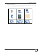
Document Conventions Icons Used in Figures Figures in this User’s Guide may use the following generic icons. The ZyXEL Device icon is not an exact representation of your device.
Safety Warnings Safety Warnings 1 For your safety, be sure to read and follow all warning notices and instructions. • Do NOT use this product near water, for example, in a wet basement or near a swimming pool. • Do NOT expose your device to dampness, dust or corrosive liquids. • Do NOT store things on the device. • Do NOT install, use, or service this device during a thunderstorm. There is a remote risk of electric shock from lightning. • Connect ONLY suitable accessories to the device.
Safety Warnings This product is recyclable. Dispose of it properly.
Safety Warnings 8 P-2302HWUDL-P1 Series User’s Guide
Contents Overview Contents Overview Introduction, Wizards and Status ......................................................................................... 31 Introducing the ZyXEL Device ................................................................................................... 33 Introducing the Web Configurator .............................................................................................. 39 Wizard Setup .........................................................................
Contents Overview Appendices and Index .........................................................................................................
Table of Contents Table of Contents About This User's Guide .......................................................................................................... 3 Document Conventions............................................................................................................ 4 Safety Warnings........................................................................................................................ 6 Contents Overview .......................................................
Table of Contents Chapter 3 Wizard Setup ........................................................................................................................... 47 3.1 Main Wizard Screen ............................................................................................................ 47 3.2 Connection Wizard .............................................................................................................. 48 3.2.1 Welcome ..........................................................
Table of Contents 5.2.4 Encryption .................................................................................................................. 87 5.2.5 One-Touch Intelligent Security Technology (OTIST) ................................................. 88 5.3 Additional Wireless Terms ................................................................................................... 88 5.4 General WLAN Screen .............................................................................................
Table of Contents 7.2.5 LAN IP Alias Screen ................................................................................................. 119 7.2.6 LAN Advanced Screen ............................................................................................. 120 Chapter 8 NAT......................................................................................................................................... 123 8.1 NAT Overview .....................................................................
Table of Contents 10.1.1 Voice Activity Detection/Silence Suppression/Comfort Noise ................................ 147 10.1.2 Echo Cancellation .................................................................................................. 147 10.1.3 Supplementary Phone Services Overview ............................................................. 147 10.2 Phone Screens ................................................................................................................ 150 10.2.
Table of Contents 13.8.3 Configuration Details: Incoming ............................................................................. 178 13.8.4 Call Progression ..................................................................................................... 179 13.9 VoIP Trunking Example: PSTN to PSTN via VoIP .......................................................... 179 13.9.1 Background Information ......................................................................................... 180 13.9.
Table of Contents Chapter 17 Bandwidth MGMT.................................................................................................................. 205 17.1 Bandwidth Management Overview .................................................................................. 205 17.1.1 Bandwidth Classes and Filters ............................................................................... 205 17.1.2 Proportional Bandwidth Allocation .................................................................
Table of Contents 19.2.1 Installing UPnP in Windows Example .................................................................... 226 19.2.2 Using UPnP in Windows XP Example ................................................................... 229 19.3 General ............................................................................................................................ 235 Chapter 20 Sharing a USB Printer ...........................................................................................
Table of Contents 22.3.3 Time Settings Screen ............................................................................................. 266 Chapter 23 Log ......................................................................................................................................... 269 23.1 Logs Overview ................................................................................................................. 269 23.1.1 Alerts ...........................................................
Table of Contents Appendix G Services............................................................................................................ 347 Appendix H Legal Information .............................................................................................. 351 Appendix I Customer Support .............................................................................................. 355 Index.....................................................................................................
List of Figures List of Figures Figure 1 ZyXEL Device’s VoIP Features ................................................................................................ 33 Figure 2 ZyXEL Device as a VoIP Trunking Gateway ............................................................................ 34 Figure 3 DECT Base Station Feature ..................................................................................................... 34 Figure 4 File Sharing Overview .........................................
List of Figures Figure 39 VoIP Statistics Window .......................................................................................................... 76 Figure 40 BW MGMT Monitor Window ................................................................................................... 78 Figure 41 Packet Statistics Window ....................................................................................................... 80 Figure 42 Example of a Wireless Network ...................................
List of Figures Figure 82 VoIP > Phone > Analog Phone ............................................................................................ 151 Figure 83 VoIP > Phone > Analog Phone > Advanced ........................................................................ 152 Figure 84 DECT Base Station Overview .............................................................................................. 153 Figure 85 DECT Base Station Button - Top of the ZyXEL Device ......................................
List of Figures Figure 125 Management > Bandwidth MGMT > Class Setup > Edit .................................................... 214 Figure 126 Management > Bandwidth MGMT > Monitor ..................................................................... 216 Figure 127 Management > Remote MGMT > WWW ........................................................................... 218 Figure 128 Management > Remote MGMT > Telnet ............................................................................
List of Figures Figure 168 Add Printer Wizard: Print Test Page ................................................................................. 247 Figure 169 Add Printer Wizard Complete ............................................................................................. 248 Figure 170 Macintosh HD ..................................................................................................................... 248 Figure 171 Macintosh HD folder .................................................
List of Figures Figure 211 Network Number and Host ID ............................................................................................ 308 Figure 212 Subnetting Example: Before Subnetting ............................................................................ 310 Figure 213 Subnetting Example: After Subnetting ............................................................................... 311 Figure 214 WIndows 95/98/Me: Network: Configuration ...............................................
List of Tables List of Tables Table 1 LED Descriptions ...................................................................................................................... 37 Table 2 Web Configurator Icons in the Title Bar .................................................................................... 43 Table 3 Navigation Panel Summary ...................................................................................................... 43 Table 4 Main Wizard Screen ................................
List of Tables Table 39 Wireless: WPA(2) ................................................................................................................... 93 Table 40 Network > Wireless LAN > OTIST .......................................................................................... 95 Table 41 MAC Address Filter ................................................................................................................ 98 Table 42 Wireless LAN: Advanced ..........................................
List of Tables Table 82 VoIP > Trunking > Peer Call ................................................................................................. 174 Table 83 VoIP > Trunking > Call Rule ................................................................................................. 176 Table 84 VoIP Trunking Call Progression ........................................................................................... 179 Table 85 PSTN to PSTN: VoIP Trunking Call Progression .............................
List of Tables Table 125 PPP Logs ............................................................................................................................ 275 Table 126 UPnP Logs ......................................................................................................................... 276 Table 127 Content Filtering Logs ........................................................................................................ 276 Table 128 Attack Logs .......................................
P ART I Introduction, Wizards and Status Introducing the ZyXEL Device (33) Introducing the Web Configurator (39) Wizard Setup (47) Status Screens (71) 31
CHAPTER 1 Introducing the ZyXEL Device This chapter introduces the main applications and features of the ZyXEL Device. 1.1 Overview This user’s guide explains how to configure the following ZyXEL devices: • The P-2302HWUD-P1 is a 4-port wireless router with Voice over IP (VoIP) communication capabilities that allow you to use a traditional analog telephone to make Internet calls. The P-2302HWUD-P1 is also a complete security solution with a robust firewall and content filtering.
Chapter 1 Introducing the ZyXEL Device • Calls via a VoIP service provider (B) - The ZyXEL Device sends your call to a VoIP service provider’s SIP server which forwards your calls to either VoIP or PSTN phones. 1.1.2 VoIP Trunking Gateway VoIP trunking allows you to use your ZyXEL Device as a gateway between VoIP and PSTN networks. Figure 2 ZyXEL Device as a VoIP Trunking Gateway In this example, you use your analog phone (A) to call the ZyXEL Device (B).
Chapter 1 Introducing the ZyXEL Device 1.1.4 ZyXEL Device’s USB Support Use the built-in USB 2.0 ports to share files via a USB memory stick or a USB hard drive (A). You can also add a printer (B) and make it available on your local area network. Figure 4 File Sharing Overview A B 1.1.5 ZyXEL Device’s Router Features Your ZyXEL Device provides shared Internet access through your existing Internet access gateway (company network, or your cable or DSL modem for example).
Chapter 1 Introducing the ZyXEL Device Use content filtering to block access to specific web sites, with URL’s containing keywords that you specify. You can define time periods and days during which content filtering is enabled and include or exclude particular computers on your network from content filtering. For example, you could block access to certain web sites for the kids.
Chapter 1 Introducing the ZyXEL Device Figure 6 LEDs on the Side Panel Figure 7 LED on the Top of the Device None of the LEDs are on if the ZyXEL Device is not receiving power. Table 1 LED Descriptions LED COLOR STATUS DESCRIPTION POWER Green On The ZyXEL Device is receiving power and ready for use. Blinking The ZyXEL Device is self-testing. On The ZyXEL Device detected an error while self-testing, or there is a device malfunction. Off The ZyXEL Device is not receiving power.
Chapter 1 Introducing the ZyXEL Device Table 1 LED Descriptions LED COLOR STATUS DESCRIPTION ETHERNET 1-4 Green On The ZyXEL Device has an Ethernet connection with a device on the Local Area Network (LAN). Blinking The ZyXEL Device is sending/receiving data to /from the LAN. Off The ZyXEL Device does not have an Ethernet connection with the LAN. On The wireless network is activated and is operating in IEEE 802.11b/g mode. Blinking The ZyXEL Device is communicating with other wireless clients.
CHAPTER 2 Introducing the Web Configurator This chapter describes how to access the ZyXEL Device web configurator and provides an overview of its screens. 2.1 Web Configurator Overview The web configurator is an HTML-based management interface that allows easy ZyXEL Device setup and management via Internet browser. Use Internet Explorer 6.0 and later or Netscape Navigator 7.0 and later versions. The recommended screen resolution is 1024 by 768 pixels.
Chapter 2 Introducing the Web Configurator Figure 8 Login Screen 4 Type "1234" (default) as the password, and click Login. In some versions, the default password appears automatically - if this is the case, click Login. The Change Password screen appears. Figure 9 Change Password Screen 5 It is highly recommended to change your password. To change your password, type a new password, retype it to confirm it, and click Apply. Otherwise, click Ignore if you do not want to change your password right now.
Chapter 2 Introducing the Web Configurator Figure 10 Select Mode Screen 6 In the Options screen, • Click Go to Wizard setup if you are logging in for the first time or if you want to make basic changes. See Chapter 3 on page 47 for more information. • Click Go to Advanced setup if you want to configure features that are not available in the wizards. The main screen appears. See Section 2.4 on page 42 for more information. • Click Exit if you want to log out.
Chapter 2 Introducing the Web Configurator 1 Make sure the POWER LED is on and not blinking. 2 Press and hold the RESET button for ten seconds. Release the RESET button when the POWER LED begins to blink. The default settings have been restored. If the ZyXEL Device restarts automatically, wait for the ZyXEL Device to finish restarting, and log in to the web configurator. The password is “1234”. You have finished.
Chapter 2 Introducing the Web Configurator 2.4.1 Title Bar The title bar provides some icons in the upper right corner. The icons provide the following functions. Table 2 Web Configurator Icons in the Title Bar ICON DESCRIPTION Wizards: Click this icon to open one of the web configurator wizards. See Chapter 3 on page 47 for more information. Logout: Click this icon to log out of the web configurator. 2.4.
Chapter 2 Introducing the Web Configurator Table 3 Navigation Panel Summary LINK NAT TAB FUNCTION General Use this screen to enable and disable NAT features. Port Forwarding Use this screen to forward traffic to specific IP addresses based on the destination port. Trigger Port Use this screen to change your ZyXEL Device’s trigger port settings. ALG Use this screen to enable and disable the ZyXEL Device’s ALG. SIP Settings Use this screen to configure your ZyXEL Device’s Voice over IP settings.
Chapter 2 Introducing the Web Configurator Table 3 Navigation Panel Summary LINK TAB FUNCTION WWW Use this screen to configure through which interface(s) and from which IP address(es) users can use HTTP to manage the ZyXEL Device. Telnet Use this screen to configure through which interface(s) and from which IP address(es) users can use Telnet to manage the ZyXEL Device.
Chapter 2 Introducing the Web Configurator 46 P-2302HWUDL-P1 Series User’s Guide
CHAPTER 3 Wizard Setup This chapter provides information on the wizards in the web configurator. 3.1 Main Wizard Screen Use this screen to open one of the wizards in the ZyXEL Device. To access this screen, click Go to Wizard setup in the Login Options screen, or click the Wizard icon in the upper right corner of the main screen.
Chapter 3 Wizard Setup The following table describes the labels in this screen. Table 4 Main Wizard Screen LABEL DESCRIPTION CONNECTION WIZARD Click this to open the Connection Wizard. See Section 3.2 on page 48. VOIP SETUP Click this to open the VoIP Setup Wizard. See Section 3.3 on page 61. BANDWIDTH MANAGEMENT WIZARD Click this to open the Bandwidth Management Wizard. See Section 3.4 on page 65. Exit Click this to close this screen and return to the main screen. 3.
Chapter 3 Wizard Setup 3.2.1 Welcome Figure 13 Connection Wizard > Welcome The following table describes the labels in this screen. Table 5 Connection Wizard > Welcome LABEL DESCRIPTION < Back Click this to go to the previous screen. Next > Click this to go to the next screen. Exit Click this to close this screen and return to the main screen. 3.2.2 System Information " Usually, you should just click Next in this screen.
Chapter 3 Wizard Setup The following table describes the labels in this screen. Table 6 Connection Wizard > System Information LABEL DESCRIPTION System Name Enter your computer's "Computer Name". See Section 22.1 on page 261 for more information. This is for identification purposes, but some ISPs also check this field. This name can be up to 30 alphanumeric characters long. Spaces are not allowed, but dashes “-” and underscores "_" are accepted.
Chapter 3 Wizard Setup Table 7 Wireless LAN Setup Wizard 2 LABEL DESCRIPTION Security Select Auto(WPA-PSK with self-generated key), if you want OTIST to configure a WPA key for you. Select Extend(WPA-PSK with customized key) or Extend(WPA2-PSK with customized key) to configure a Pre-Shared Key (WPA-PSK). Choose this option only if your wireless clients support WPA or WPA2. See Section 3.2.3.2 on page 51 for more information. Select Basic(WEP) to configure a WEP Key. See Section 3.2.3.
Chapter 3 Wizard Setup 3.2.3.3 Manually Assign a WEP key Choose Basic(WEP) to setup WEP encryption parameters. Figure 17 Manually Assign a WEP key The following table describes the labels in this screen. Table 9 Manually Assign a WEP key LABEL DESCRIPTION Passphrase Enter a Passphrase (up to 32 printable characters) and clicking Generate. The ZyXEL Device automatically generates a WEP key. WEP Encryption Select 64-bit WEP, 128-bit WEP or 256-bit WEP to specify data encryption.
Chapter 3 Wizard Setup Figure 18 Manually Assign a WEP key The following table describes the labels in this screen. Table 10 Manually Assign a WEP key LABEL DESCRIPTION Do you want to Select Yes and the ZyXEL Device will automatically start OTIST once you finish the enable OTIST configuration wizard. Select No if you do not want to use OTIST. Note: You must Start OTIST in the ZyXEL Device and in the wireless device(s) within three minutes of each other.
Chapter 3 Wizard Setup 3.2.4.1 Ethernet " You cannot use the Connection Wizard if you subscribe to a Roadrunner service. You must use the screens discussed in Chapter 6 on page 101 instead. Figure 19 Connection Wizard > ISP Parameters (Ethernet) The following table describes the labels in this screen. Table 11 Connection Wizard > ISP Parameters (Ethernet) LABEL DESCRIPTION Connection Type Select Ethernet. < Back Click this to go to the previous screen. Next > Click this to go to the next screen.
Chapter 3 Wizard Setup Figure 20 Connection Wizard > ISP Parameters (PPPoE) The following table describes the labels in this screen. Table 12 Connection Wizard > ISP Parameters (PPPoE) LABEL DESCRIPTION Connection Type Select PPP over Ethernet. Service Name Enter the PPP service name provided by your ISP. If your ISP did not provide a service name, leave this field blank. User Name Enter the user name provided by your ISP. Password Enter the password provided by your ISP.
Chapter 3 Wizard Setup The following table describes the labels in this screen. Table 13 Connection Wizard > IP Address LABEL DESCRIPTION Get automatically from your ISP Select this if your ISP did not assign you a static IP address. Use fixed IP address provided by your ISP Select this if your ISP assigned you a static IP address. < Back Click this to go to the previous screen. Next > Click this to go to the next screen. Exit Click this to close this screen and return to the main screen. 3.2.
Chapter 3 Wizard Setup The following table describes the labels in this screen. Table 14 Connection Wizard > IP Address (Ethernet) LABEL DESCRIPTION My WAN IP Address Enter the IP address provided by your ISP. My WAN IP Subnet Mask Enter the subnet mask provided by your ISP. Gateway IP Address Enter the gateway provided by your ISP. If your ISP did not provide one, leave it blank.
Chapter 3 Wizard Setup Figure 23 Connection Wizard > IP Address (PPPoE) The following table describes the labels in this screen. Table 15 Connection Wizard > IP Address (PPPoE) 58 LABEL DESCRIPTION My WAN IP Address Enter the IP address provided by your ISP. First DNS Server Second DNS Server Third DNS Server Enter the IP addresses of the DNS servers. If you have only one DNS server, enter its IP address in the First DNS Server field and leave the remaining fields at default.
Chapter 3 Wizard Setup 3.2.7 MAC Address Figure 24 Connection Wizard > MAC Address The following table describes the labels in this screen. Table 16 Connection Wizard > MAC Address LABEL DESCRIPTION Factory default Select this if you want to use the default MAC address for the ZyXEL Device. Spoof this computer’s MAC Address Select this if you do not want to use the default MAC address for the ZyXEL Device. IP Address This field is enabled if you select Spoof WAN MAC Address.
Chapter 3 Wizard Setup 3.2.8 Apply the Connection Wizard Setting Figure 25 Connection Wizard > Apply The following table describes the labels in this screen. Table 17 Connection Wizard > Apply 60 LABEL DESCRIPTION < Back Click this to go to the previous screen. Apply Click this to save your changes back to the ZyXEL Device. Exit Click this to close this screen and return to the main screen.
Chapter 3 Wizard Setup 3.2.9 Finish Figure 26 Connection Wizard > Finish The following table describes the labels in this screen. Table 18 Connection Wizard > Finish LABEL DESCRIPTION Go to Bandwidth Management Wizard (optional) Click this to start the Bandwidth Management Wizard. See Section 3.4 on page 65. Finish Click this to close this screen and return to the main screen. 3.3 VoIP Setup Wizard Use this wizard to set up your VoIP account(s).
Chapter 3 Wizard Setup 3.3.1 SIP Settings Figure 27 VoIP Setup Wizard > SIP Settings The following table describes the labels in this screen. Table 19 VoIP Setup Wizard > SIP Settings LABEL DESCRIPTION SIP1 (- SIP10) Settings Use this screen to configure SIP settings for up to 10 SIP accounts. SIP Number Enter your SIP number. In the full SIP URI (like 1234@VoIP-provider.com), this is the part before the @ symbol. You can use up to 127 printable ASCII characters.
Chapter 3 Wizard Setup Table 19 VoIP Setup Wizard > SIP Settings LABEL SIP Account DESCRIPTION Select a SIP account you want to configure. The SIP Settings screen appears again for the specified SIP account. Once you finish configuring all of your SIP accounts, click apply. The ZyXEL Device tries to register your SIP account(s). The following screen appears. Figure 28 VoIP Setup Wizard > Registration Test Wait until it finishes. < Back Click this to go to the previous screen.
Chapter 3 Wizard Setup Figure 29 VoIP Setup Wizard > Registration Complete (Success) The following table describes the labels in this screen. Table 20 VoIP Setup Wizard > Registration Complete (Success) LABEL DESCRIPTION Return to Wizard Main Page Click this to open the main wizard screen. See Section 3.1 on page 47. Go to Advanced Setup page Click this to close this screen and return to the main screen. Finish Click this to close this screen and return to the main screen.
Chapter 3 Wizard Setup Figure 30 VoIP Setup Wizard > Registration Complete (Fail) The following table describes the labels in this screen. Table 21 VoIP Setup Wizard > Registration Complete (Fail) LABEL DESCRIPTION < Back Click this to go to the previous screen. Register Again Click this if you want the ZyXEL Device to try to register your SIP account(s) again. Exit Click this to close this screen and return to the main screen. The ZyXEL Device saves the information you provided. 3.
Chapter 3 Wizard Setup 3.4.1 Welcome Figure 31 Bandwidth Management Wizard > Welcome The following table describes the labels in this screen. Table 22 Bandwidth Management Wizard > Welcome 66 LABEL DESCRIPTION < Back Click this to go to the previous screen. Next > Click this to go to the next screen. Exit Click this to close this screen and return to the main screen.
Chapter 3 Wizard Setup 3.4.2 General Information Figure 32 Bandwidth Management Wizard > General Information The following table describes the labels in this screen. Table 23 Bandwidth Management Wizard > General Information LABEL DESCRIPTION Active Select this to enable bandwidth management. Bandwidth management applies to all traffic flowing through the router. Managed Bandwidth (kbps) Enter the total amount of traffic the device can send to the WAN.
Chapter 3 Wizard Setup 3.4.3 Services Setup Figure 33 Bandwidth Management Wizard > Services Setup The following table describes the labels in this screen. Table 24 Bandwidth Management Wizard > Services Setup LABEL DESCRIPTION Service Select the service(s) that should have higher priority when bandwidth is allocated. If you do not select a service or if you do not see it in the list, the service can still use bandwidth. However, it has the lowest priority.
Chapter 3 Wizard Setup 3.4.4 Priority Setup Figure 34 Bandwidth Management Wizard > Priority Setup The following table describes the labels in this screen. Table 25 Bandwidth Management Wizard > Priority Setup LABEL DESCRIPTION Service This column displays each service you selected in the previous screen. Priority Set the priority of each service. If a service has higher priority than other services, then it can use as much remaining bandwidth as it needs.
Chapter 3 Wizard Setup 3.4.5 Finish Figure 35 Bandwidth Management Wizard > Finish The following table describes the labels in this screen. Table 26 Bandwidth Management Wizard > Finish 70 LABEL DESCRIPTION Finish Click this to close this screen and return to the main screen.
CHAPTER 4 Status Screens Use the Status screens to look at the current status of the device, system resources, traffic flow, interfaces (LAN, WAN and WLAN), and SIP accounts. You can also register and unregister SIP accounts. 4.1 Status Screen Use this screen to look at the current status of the device, system resources, interfaces (LAN and WAN), and SIP accounts. You can also register and unregister SIP accounts. Click Status to open this screen.
Chapter 4 Status Screens Each field is described in the following table. Table 27 Status Screen LABEL DESCRIPTION Refresh Interval Enter how often you want the ZyXEL Device to update this screen. Refresh Now Click this to update this screen immediately. Device Information System Name This field displays the ZyXEL Device system name. It is used for identification. You can change this in the Configuration Wizard or Maintenance > System > General screen.
Chapter 4 Status Screens Table 27 Status Screen LABEL DESCRIPTION System Resource CPU Usage This field displays what percentage of the ZyXEL Device’s processing ability is currently used. When this percentage is close to 100%, the ZyXEL Device is running at full load, and the throughput is not going to improve anymore. If you want some applications to have more throughput, you should turn off other applications (for example, using bandwidth management; see Chapter 17 on page 205.
Chapter 4 Status Screens Table 27 Status Screen LABEL DESCRIPTION Registration This field displays the current registration status of the SIP account. You have to register SIP accounts with a SIP server to use VoIP. If the SIP account is already registered with the SIP server, • Click Unregister to delete the SIP account’s registration in the SIP server. This does not cancel your SIP account, but it deletes the mapping between your SIP identity and your IP address or domain name.
Chapter 4 Status Screens 4.3 DHCP Table Window To access this screen, open the Status screen (see Section 4.1 on page 71), and click (Details ...) next to DHCP Table. Figure 38 DHCP Table Window Each field is described in the following table. Table 29 DHCP Table Window LABEL DESCRIPTION # This field is a sequential value. It is not associated with a specific entry. IP Address This field displays the IP address the ZyXEL Device assigned to a computer in the network.
Chapter 4 Status Screens Figure 39 VoIP Statistics Window Each field is described in the following table. Table 30 VoIP Statistics Window LABEL DESCRIPTION SIP Status Account This column displays each SIP account in the ZyXEL Device. Registration This field displays the current registration status of the SIP account. You can change this in the Status screen. Registered - The SIP account is registered with a SIP server.
Chapter 4 Status Screens Table 30 VoIP Statistics Window LABEL DESCRIPTION Status This field displays the current status of each call. DIAL - The ZyXEL Device is dialing the current call. RING - The phone is ringing because there is an incoming call. Process - The call is connected and in process. DROP - The ZyXEL Device is hanging up (disconnecting) the current call. DISC - The ZyXEL Device has hung up. N/A - There is no phone connected to this phone port.
Chapter 4 Status Screens Figure 40 BW MGMT Monitor Window The types of traffic shown in this screen do not depend on your settings in the Bandwidth Management Wizard or in Bandwidth MGMT. Each field is described in the following table. Table 31 BW MGMT Monitor Window 78 LABEL DESCRIPTION LAN-VoIP (SIP) This field displays how much SIP traffic is going to the LAN each second. The rate is the number of kilobits that went to the LAN one second before the last time the screen updated (refreshed).
Chapter 4 Status Screens Table 31 BW MGMT Monitor Window LABEL DESCRIPTION WAN-VoIP (SIP) This field displays how much SIP traffic went to the WAN each second. The rate is the number of kilobits that went to the WAN one second before the last time the screen updated (refreshed). WAN-FTP This field displays how much FTP traffic went to the WAN each second. The rate is the number of kilobits that went to the WAN one second before the last time the screen updated (refreshed).
Chapter 4 Status Screens Figure 41 Packet Statistics Window Each field is described in the following table. Table 32 Packet Statistics Window 80 LABEL DESCRIPTION Port This field displays each port in the ZyXEL Device. Status If the port is not connected to anything, this field displays Down. If the interface uses Ethernet encapsulation, this field displays the port speed and the Ethernet duplex setting. Duplex settings are: Full - The ZyXEL Device is using full-duplex Ethernet.
Chapter 4 Status Screens Table 32 Packet Statistics Window LABEL DESCRIPTION Set Interval Click this to make the ZyXEL Device update the screen based on the amount of time you specified in Poll Interval. Stop Click this to make the ZyXEL Device stop updating the screen.
Chapter 4 Status Screens 82 P-2302HWUDL-P1 Series User’s Guide
P ART II Network Wireless LAN (85) WAN (101) LAN (111) NAT (123) 83
CHAPTER 5 Wireless LAN This chapter discusses how to configure the wireless network settings in your ZyXEL Device. See the appendices for more detailed information about wireless networks. 5.1 Wireless Network Overview The following figure provides an example of a wireless network. Figure 42 Example of a Wireless Network The wireless network is the part in the blue circle.
Chapter 5 Wireless LAN • Every device in the same wireless network must use security compatible with the AP. Security stops unauthorized devices from using the wireless network. It can also protect the information that is sent in the wireless network. 5.2 Wireless Security Overview The following sections introduce different types of wireless security you can set up in the wireless network. 5.2.1 SSID Normally, the ZyXEL Device acts like a beacon and regularly broadcasts the SSID in the area.
Chapter 5 Wireless LAN Unauthorized wireless devices can still see the information that is sent in the wireless network, even if they cannot use the wireless network. Furthermore, there are ways for unauthorized wireless users to get a valid user name and password. Then, they can use that user name and password to use the wireless network. 5.2.4 Encryption Wireless networks can use encryption to protect the information that is sent in the wireless network. Encryption is like a secret code.
Chapter 5 Wireless LAN 5.2.5 One-Touch Intelligent Security Technology (OTIST) With ZyXEL’s OTIST, you set up the SSID and the encryption (WEP or WPA-PSK) on the ZyXEL Device. Then, the ZyXEL Device transfers them to the devices in the wireless networks. As a result, you do not have to set up the SSID and encryption on every device in the wireless network. The devices in the wireless network have to support OTIST, and they have to be in range of the ZyXEL Device when you activate it. See Section 5.
Chapter 5 Wireless LAN Figure 43 Wireless LAN: General The following table describes the general wireless LAN labels in this screen. Table 35 Wireless LAN: General LABEL DESCRIPTION Enable Wireless LAN Click the check box to activate wireless LAN. Name(SSID) (Service Set IDentity) The SSID identifies the Service Set with which a wireless station is associated. Wireless stations associating to the access point (AP) must have the same SSID.
Chapter 5 Wireless LAN " If you do not enable any wireless security on your ZyXEL Device, your network is accessible to any wireless networking device that is within range. Figure 44 Wireless: No Security The following table describes the labels in this screen. Table 36 Wireless No Security LABEL DESCRIPTION Security Mode Choose No Security from the drop-down list box. 5.4.
Chapter 5 Wireless LAN Figure 45 Wireless: Static WEP Encryption The following table describes the wireless LAN security labels in this screen. Table 37 Wireless: Static WEP Encryption LABEL DESCRIPTION Security Mode Choose Static WEP from the drop-down list box. Passphrase Enter a Passphrase (up to 32 printable characters) and clicking Generate. The ZyXEL Device automatically generates a WEP key. WEP Encryption Select 64-bit WEP, 128-bit WEP or 256-bit WEP to specify data encryption.
Chapter 5 Wireless LAN Figure 46 Wireless: WPA(2)-PSK The following table describes the wireless LAN security labels in this screen. Table 38 Wireless: WPA(2)-PSK LABEL DESCRIPTION Security Mode Choose WPA-PSK or WPA2-PSK from the drop-down list box. WPA Compatible This field is only available for WPA2-PSK. Select this if you want the ZyXEL Device to support WPA-PSK and WPA2-PSK simultaneously. Pre-Shared Key The encryption mechanisms used for WPA(2) and WPA(2)-PSK are the same.
Chapter 5 Wireless LAN 5.4.4 WPA(2) Authentication Screen In order to configure and enable WPA Authentication; click the Wireless LAN link under Network to display the Wireless screen. Select WPA or WPA2 from the Security list. Figure 47 Wireless: WPA(2) The following table describes the wireless LAN security labels in this screen. Table 39 Wireless: WPA(2) LABEL DESCRIPTION Security Mode Choose WPA or WPA2 from the drop-down list box. WPA Compatible This field is only available for WPA2.
Chapter 5 Wireless LAN Table 39 Wireless: WPA(2) LABEL DESCRIPTION Group Key Update Timer The Group Key Update Timer is the rate at which the AP (if using WPA-PSK key management) or RADIUS server (if using WPA key management) sends a new group key out to all clients. The re-keying process is the WPA equivalent of automatically changing the WEP key for an AP and all stations in a WLAN on a periodic basis. Setting of the Group Key Update Timer is also supported in WPA-PSK mode.
Chapter 5 Wireless LAN The following table describes the labels in this screen. Table 40 Network > Wireless LAN > OTIST LABEL DESCRIPTION Setup Key Type a key (password) 8 ASCII characters long. Note: If you change the OTIST setup key in the ZyXEL Device, you must change it on the wireless devices too. Yes! Select this if you want the ZyXEL Device to automatically generate a preshared key for the wireless network.
Chapter 5 Wireless LAN " You must click Start in the ZyXEL Device and in the wireless device(s) within three minutes of each other. You can start OTIST in the wireless devices and the ZyXEL Device in any order. After you click Start in the ZyXEL Device, the following screen appears (in the ZyXEL Device). Figure 50 OTIST: Settings You can use the key in this screen to set up WPA-PSK encryption manually for non-OTIST devices in the wireless network. Review the settings, and click OK.
Chapter 5 Wireless LAN Figure 52 Start OTIST? 2 If an OTIST-enabled wireless device loses its wireless connection for more than ten seconds, it will search for an OTIST-enabled AP for up to one minute. (If you manually have the wireless device search for an OTIST-enabled AP, there is no timeout; click Cancel in the OTIST progress screen to stop the search.
Chapter 5 Wireless LAN Figure 53 MAC Address Filter The following table describes the labels in this menu. Table 41 MAC Address Filter 98 LABEL DESCRIPTION Active Select the check box to enable MAC address filtering. Filter Action Define the filter action for the list of MAC addresses in the MAC Address table.
Chapter 5 Wireless LAN 5.7 Wireless LAN Advanced Setup To configure advanced wireless settings, click the Advanced Setup button in the General screen. The screen appears as shown. Figure 54 Wireless LAN: Advanced The following table describes the labels in this screen. Table 42 Wireless LAN: Advanced LABEL DESCRIPTION Wireless Advanced Setup RTS/CTS Threshold Enter a value between 0 and 2432. Fragmentation Threshold It is the maximum data fragment size that can be sent.
Chapter 5 Wireless LAN 100 P-2302HWUDL-P1 Series User’s Guide
CHAPTER 6 WAN 6.1 WAN Overview Use these screens to set up the ZyXEL Device on the WAN. You can configure the Internet connection, DNS servers, and how the ZyXEL Device sends routing information using RIP. In addition, you can set up a backup gateway in case the default gateway is not available. 6.1.1 PPPoE Encapsulation The ZyXEL Device supports PPPoE (Point-to-Point Protocol over Ethernet).
Chapter 6 WAN You can obtain your IP address from the IANA, from an ISP or have it assigned by a private network. If you belong to a small organization and your Internet access is through an ISP, the ISP can provide you with the Internet addresses for your local networks. On the other hand, if you are part of a much larger organization, you should consult your network administrator for the appropriate IP addresses.
Chapter 6 WAN 2 If the ISP did not give you DNS server information, leave the DNS Server fields in the SYSTEM General screen set to 0.0.0.0 for the ISP to dynamically assign the DNS server IP addresses. 6.2 WAN Screens 6.2.1 WAN Internet Connection Screen (Ethernet) Use this screen to set up your Internet connection. This screen depends on the type of Internet connection you have. Use this screen to set up an Ethernet connection (no Roadrunner service) with the ISP.
Chapter 6 WAN Each field is described in the following table. Table 44 Network > WAN > Internet Connection (Ethernet) LABEL DESCRIPTION ISP Parameters for Internet Access Encapsulation Select Ethernet. Ethernet encapsulation with Service Type set to Standard is typically used if you are extending your existing network. Service Type Select Standard.
Chapter 6 WAN Figure 56 Network > WAN > Internet Connection (Roadrunner) Each field is described in the following table. Table 45 Network > WAN > Internet Connection (Roadrunner) LABEL DESCRIPTION ISP Parameters for Internet Access Encapsulation Select Ethernet. Service Type Select the Roadrunner service provided by your ISP. User Name Enter the user name provided by your ISP. Password Enter the password provided by your ISP.
Chapter 6 WAN Figure 57 Network > WAN > Internet Connection (PPPoE) Each field is described in the following table. Table 46 Network > WAN > Internet Connection (PPPoE) LABEL DESCRIPTION ISP Parameters for Internet Access Encapsulation Select PPP over Ethernet. Service Name Enter the PPP service name provided by your ISP. If your ISP did not provide a service name, leave this field blank. User Name Enter the user name provided by your ISP. Password Enter the password provided by your ISP.
Chapter 6 WAN Table 46 Network > WAN > Internet Connection (PPPoE) LABEL DESCRIPTION Get automatically from ISP Select this if your ISP did not assign you a static IP address. Use Fixed IP Address Select this if your ISP assigned you a static IP address. My WAN IP Address Enter the IP address provided by your ISP. Remote IP Address Enter the IP address your ISP provided for the remote (peer) server. Remote IP Subnet Mask Enter the subnet mask your ISP provided for the remote server.
Chapter 6 WAN Figure 58 Network > WAN > Advanced Each field is described in the following table. Table 47 Network > WAN > Advanced LABEL DESCRIPTION DNS Servers DNS (Domain Name System) manages the relationships between domain names and IP addresses. Without a DNS server, you must know the IP address of the computer you want to access before you access it. First DNS Server Second DNS Server Third DNS Server Select From ISP if your ISP dynamically assigns DNS server information.
Chapter 6 WAN Table 47 Network > WAN > Advanced LABEL DESCRIPTION Multicast Select which version of IGMP the ZyXEL Device uses to support multicasting on the WAN. Multicasting sends packets to some computers on the WAN and is an alternative to unicasting (sending packets to one computer) and broadcasting (sending packets to every computer). None - The ZyXEL Device does not support multicasting. IGMP-v1 - The ZyXEL Device supports IGMP version 1. IGMP-v2 - The ZyXEL Device supports IGMP version 2.
Chapter 6 WAN Each field is described in the following table. Table 48 Network > WAN > Traffic Redirect 110 LABEL DESCRIPTION Active Select this to set up a backup gateway in case the default gateway is not available. (For example, this might happen if the Internet connection goes down.) Clear this if you do not have a backup gateway. Backup Gateway IP Address Enter the IP address of the backup gateway. The ZyXEL Device automatically uses this gateway if the default gateway is not available anymore.
CHAPTER 7 LAN Use these screens to set up the ZyXEL Device on the LAN. You can configure its IP address and subnet mask, DHCP services, and other subnets. You can also control how the ZyXEL Device sends routing information using RIP, and you can enable and disable Any IP. 7.1 LAN Overview A Local Area Network (LAN) is a shared communication system to which many computers are attached. A LAN is usually a computer network limited to the immediate area, such as the same building or floor of a building. 7.
Chapter 7 LAN 7.1.2 DHCP Setup DHCP (Dynamic Host Configuration Protocol, RFC 2131 and RFC 2132) allows individual clients to obtain TCP/IP configuration at start-up from a server. You can configure the ZyXEL Device as a DHCP server or disable it. When configured as a server, the ZyXEL Device provides the TCP/IP configuration for the clients. If DHCP service is disabled, you must have another DHCP server on your LAN, or else each computer must be manually configured.
Chapter 7 LAN Please note that DNS proxy works only when the ISP uses the IPCP DNS server extensions. It does not mean you can leave the DNS servers out of the DHCP setup under all circumstances. If your ISP gives you explicit DNS servers, make sure that you enter their IP addresses in the LAN Setup screen. This way, the ZyXEL Device can pass the DNS servers to the computers and the computers can query the DNS server directly without the ZyXEL Device’s intervention. 7.1.
Chapter 7 LAN The ZyXEL Device supports both IGMP version 1 (IGMP-v1) and IGMP version 2 (IGMPv2). At start up, the ZyXEL Device queries all directly connected networks to gather group membership. After that, the ZyXEL Device periodically updates this information. IP multicasting can be enabled/disabled on the ZyXEL Device LAN and/or WAN interfaces in the web configurator (LAN; WAN). Select None to disable IP multicasting on these interfaces. 7.1.
Chapter 7 LAN " You must enable NAT to use the Any IP feature on the ZyXEL Device. Address Resolution Protocol (ARP) is a protocol for mapping an Internet Protocol address (IP address) to a physical machine address, also known as a Media Access Control or MAC address, on the local area network. IP routing table is defined on IP Ethernet devices (the ZyXEL Device) to decide which hop to use, to help forward data along to its specified destination.
Chapter 7 LAN Each field is described in the following table. Table 49 Network > LAN > IP LABEL DESCRIPTION IP Address Enter the IP address of the ZyXEL Device on the LAN. Note: This field is the IP address you use to access the ZyXEL Device on the LAN. If the web configurator is running on a computer on the LAN, you lose access to the web configurator as soon as you change this field and click Apply. You can access the web configurator again by typing the new IP address in the browser.
Chapter 7 LAN Table 50 Network > LAN > DHCP Setup LABEL DESCRIPTION Pool Size Enter the number of IP addresses to allocate. This number must be at least one and is limited by a subnet mask of 255.255.255.0 (regardless of the subnet the ZyXEL Device is in). For example, if the IP Pool Start Address is 10.10.10.10, the ZyXEL Device can allocate up to 10.10.10.254, or 245 IP addresses.
Chapter 7 LAN Each field is described in the following table. Table 51 Network > LAN > Static DHCP LABEL DESCRIPTION # This field is a sequential value. It is not associated with a specific entry. MAC Address Enter the MAC address of the computer to which you want the ZyXEL Device to assign the same IP address. IP Address Enter the IP address you want the ZyXEL Device to assign to the computer. Apply Click this to save your changes and to apply them to the ZyXEL Device.
Chapter 7 LAN 7.2.5 LAN IP Alias Screen Use this screen to add subnets on the LAN port. You can also control what routing information is sent and received by each subnet. To access this screen, click Network > LAN > IP Alias. Figure 65 Network > LAN > IP Alias Each field is described in the following table. Table 53 Network > LAN > IP Alias LABEL DESCRIPTION IP Alias 1 IP Alias 1 Select this to add the specified subnet to the LAN port.
Chapter 7 LAN Table 53 Network > LAN > IP Alias LABEL DESCRIPTION RIP Direction Use this field to control how much routing information the ZyXEL Device sends and receives on the subnet. None - The ZyXEL Device does not send or receive routing information on the subnet. Both - The ZyXEL Device sends and receives routing information on the subnet. In Only - The ZyXEL Device only receives routing information on the subnet. Out Only - The ZyXEL Device only sends routing information on the subnet.
Chapter 7 LAN Each field is described in the following table. Table 54 Network > LAN > Advanced LABEL DESCRIPTION RIP & Multicast Setup RIP Direction Use this field to control how much routing information the ZyXEL Device sends and receives on the subnet. None - The ZyXEL Device does not send or receive routing information on the subnet. Both - The ZyXEL Device sends and receives routing information on the subnet. In Only - The ZyXEL Device only receives routing information on the subnet.
Chapter 7 LAN 122 P-2302HWUDL-P1 Series User’s Guide
CHAPTER 8 NAT 8.1 NAT Overview Use these screens to configure port forwarding and trigger ports for the ZyXEL Device. You can also enable and disable SIP, FTP, and H.323 ALG. 8.1.1 Port Forwarding: Services and Port Numbers A NAT server set is a list of inside (behind NAT on the LAN) servers, for example, web or FTP, that you can make accessible to the outside world even though NAT makes your whole inside network appear as a single machine to the outside world.
Chapter 8 NAT 8.1.2 Trigger Port Forwarding Some services use a dedicated range of ports on the client side and a dedicated range of ports on the server side. With regular port forwarding you set a forwarding port in NAT to forward a service (coming in from the server on the WAN) to the IP address of a computer on the client side (LAN). The problem is that port forwarding only forwards a service to a single LAN IP address.
Chapter 8 NAT 8.1.3 SIP ALG Some NAT routers may include a SIP Application Layer Gateway (ALG). A SIP ALG allows SIP calls to pass through NAT by examining and translating IP addresses embedded in the data stream. When the ZyXEL Device registers with the SIP register server, the SIP ALG translates the ZyXEL Device’s private IP address inside the SIP data stream to a public IP address. You do not need to use STUN or an outbound proxy (see Chapter 9 on page 133) if your ZyXEL Device is behind a SIP ALG. 8.
Chapter 8 NAT 8.2.2 NAT Port Forwarding Screen Use this screen to look at the current port-forwarding rules in the ZyXEL Device, and to enable, disable, activate, and deactivate each one. You can also set up a default server to handle ports not covered by rules. To access this screen, click Network > NAT > Port Forwarding. Figure 70 Network > NAT > Port Forwarding Each field is described in the following table.
Chapter 8 NAT Table 56 Network > NAT > Port Forwarding LABEL DESCRIPTION Modify This column provides icons to edit and delete rules. To edit a rule, click the Edit icon next to the rule. The NAT Port Forwarding Edit screen appears. To delete a rule, click the Remove icon next to the rule. All the information in the rule returns to the default settings. Apply Click this to save your changes and to apply them to the ZyXEL Device.
Chapter 8 NAT Figure 72 Network > NAT > Trigger Port Each field is described in the following table. Table 58 Network > NAT > Trigger Port LABEL DESCRIPTION Name Enter a name to identify this rule. You can use 1 - 15 printable ASCII characters, or you can leave this field blank. It does not have to be a unique name. Incoming Start Port End Port Enter the incoming port number or range of port numbers you want to forward to the IP address the ZyXEL Device records.
Chapter 8 NAT 8.2.5 NAT ALG Screen Use this screen to enable and disable SIP (VoIP), FTP (file transfer), and H.323 (audio-visual) ALG in the ZyXEL Device. To access this screen, click Network > NAT > ALG. Figure 73 Network > NAT > ALG Each field is described in the following table. Table 59 Network > NAT > ALG LABEL DESCRIPTION Enable SIP ALG Select this to make sure SIP (VoIP) works correctly with port-forwarding and porttriggering rules.
Chapter 8 NAT 130 P-2302HWUDL-P1 Series User’s Guide
P ART III VoIP SIP (133) Phone (147) Phone Book (163) PSTN Line (167) VoIP Trunking (169) 131
CHAPTER 9 SIP Use these screens to set up your SIP accounts and to configure QoS settings. 9.1 SIP Overview 9.1.1 Introduction to VoIP VoIP (Voice over IP) is the sending of voice signals over the Internet Protocol. This allows you to make phone calls and send faxes over the Internet at a fraction of the cost of using the traditional circuit-switched telephone network. You can also use servers to run telephone service applications like PBX services and voice mail.
Chapter 9 SIP 9.1.3.2 SIP Service Domain The SIP service domain of the VoIP service provider (the company that lets you make phone calls over the Internet) is the domain name in a SIP URI. For example, if the SIP address is 1122334455@VoIP-provider.com, then “VoIP-provider.com” is the SIP service domain. 9.1.4 SIP Call Progression The following figure displays the basic steps in the setup and tear down of a SIP call. A calls B. Table 60 SIP Call Progression A B 1. INVITE 2. Ringing 3. OK 4. ACK 5.
Chapter 9 SIP Figure 74 SIP User Agent 9.1.5.2 SIP Proxy Server A SIP proxy server receives requests from clients and forwards them to another server. In the following example, you want to use client device A to call someone who is using client device C. 1 The client device (A in the figure) sends a call invitation to the SIP proxy server (B). 2 The SIP proxy server forwards the call invitation to C. Figure 75 SIP Proxy Server 9.1.5.
Chapter 9 SIP Figure 76 SIP Redirect Server 9.1.5.4 SIP Register Server A SIP register server maintains a database of SIP identity-to-IP address (or domain name) mapping. The register server checks your user name and password when you register. 9.1.6 RTP When you make a VoIP call using SIP, the RTP (Real time Transport Protocol) is used to handle voice data transfer. See RFC 1889 for details on RTP. 9.1.7 NAT and SIP The ZyXEL Device must register its public IP address with a SIP register server.
Chapter 9 SIP 9.1.7.2 Use NAT If you know the NAT router’s public IP address and SIP port number, you can use the Use NAT feature to manually configure the ZyXEL Device to use a them in the SIP messages. This eliminates the need for STUN or a SIP ALG. You must also configure the NAT router to forward traffic with this port number to the ZyXEL Device. 9.1.7.
Chapter 9 SIP • G.729 is an Analysis-by-Synthesis (AbS) hybrid waveform codec that uses a filter based on information about how the human vocal tract produces sounds. G.729 provides good sound quality and reduces the required bandwidth to 8kbps. 9.1.9 PSTN Call Setup Signaling PSTNs (Public Switched Telephone Networks) use DTMF or pulse dialing to set up telephone calls. Dual-Tone Multi-Frequency (DTMF) signaling uses pairs of frequencies (one lower frequency and one higher frequency) to set up calls.
Chapter 9 SIP 9.2.0.2 Listening to Custom Tones Do the following to listen to a custom tone: 1 Pick up the phone and press “****” on your phone’s keypad and wait for the message that says you are in the configuration menu. 2 Press a number from 1201~1208 followed by the “#” key to listen to the tone. 3 You can continue to add, listen to, or delete tones, or you can hang up the receiver when you are done. 9.2.0.
Chapter 9 SIP DSCP is backward compatible with the three precedence bits in the ToS octet so that nonDiffServ compliant, ToS-enabled network device will not conflict with the DSCP mapping. The DSCP value determines the forwarding behavior, the PHB (Per-Hop Behavior), that each packet gets across the DiffServ network. Based on the marking rule, different kinds of traffic can be marked for different priorities of forwarding.
Chapter 9 SIP Each field is described in the following table. Table 62 VoIP > SIP > SIP Settings LABEL DESCRIPTION SIP Account Select the SIP account you want to see in this screen. If you change this field, the screen automatically refreshes. SIP Settings Active SIP Account Select this if you want the ZyXEL Device to use this account. Clear it if you do not want the ZyXEL Device to use this account. Number Enter your SIP number. In the full SIP URI, this is the part before the @ symbol.
Chapter 9 SIP Figure 80 VoIP > SIP > SIP Settings > Advanced 142 P-2302HWUDL-P1 Series User’s Guide
Chapter 9 SIP Each field is described in the following table. Table 63 VoIP > SIP > SIP Settings > Advanced LABEL DESCRIPTION SIP Account This field displays the SIP account you see in this screen. SIP Server Settings URL Type Select whether or not to include the SIP service domain name when the ZyXEL Device sends the SIP number.
Chapter 9 SIP Table 63 VoIP > SIP > SIP Settings > Advanced LABEL DESCRIPTION DTMF Mode Control how the ZyXEL Device handles the tones that your telephone makes when you push its buttons. You should use the same mode your VoIP service provider uses. RFC 2833 - send the DTMF tones in RTP packets PCM - send the DTMF tones in the voice data stream. This method works best when you are using a codec that does not use compression (like G.711). Codecs that use compression (like G.729) can distort the tones.
Chapter 9 SIP Table 63 VoIP > SIP > SIP Settings > Advanced LABEL DESCRIPTION Enable Select this if you want to hear a waiting (beeping) dial tone on your phone when you have at least one voice message. Your VoIP service provider must support this feature. Expiration Time Keep the default value, unless your VoIP service provider tells you to change it. Enter the number of seconds the SIP server should provide the message waiting service each time the ZyXEL Device subscribes to the service.
Chapter 9 SIP Each field is described in the following table. Table 64 VoIP > SIP > QoS 146 LABEL DESCRIPTION SIP TOS Priority Setting Enter the priority for SIP voice transmissions. The ZyXEL Device creates Type of Service priority tags with this priority to voice traffic that it transmits. RTP TOS Priority Setting Enter the priority for RTP voice transmissions. The ZyXEL Device creates Type of Service priority tags with this priority to RTP traffic that it transmits.
CHAPTER 10 Phone The following sections describe how to configure the ZyXEL Device to work with analog phones and how to configure the ZyXEL Device’s built in DECT base station to work with DECT phones. 10.1 Analog Phone Overview You can configure the volume, echo cancellation and VAD settings for each individual phone port on the ZyXEL Device. You can also select which SIP account to use for making outgoing calls. 10.1.
Chapter 10 Phone " To take full advantage of the supplementary phone services available though the ZyXEL Device's phone ports, you may need to subscribe to the services from your VoIP service provider. 10.1.3.1 The Flash Key Flashing means to press the hook for a short period of time (a few hundred milliseconds) before releasing it. On newer telephones, there should be a "flash" key (button) that generates the signal electronically.
Chapter 10 Phone 10.1.3.2.2 European Call Waiting This allows you to place a call on hold while you answer another incoming call on the same telephone (directory) number. If there is a second call to a telephone number, you will hear a call waiting tone. Take one of the following actions. • Reject the second call. Press the flash key and then press “0”. • Disconnect the first call and answer the second call.
Chapter 10 Phone 10.1.3.3.1 USA Call Hold Call hold allows you to put a call (A) on hold by pressing the flash key. If you have another call, press the flash key to switch back and forth between caller A and B by putting either one on hold. If you hang up the phone but a caller is still on hold, there will be a remind ring. 10.1.3.3.2 USA Call Waiting This allows you to place a call on hold while you answer another incoming call on the same telephone (directory) number.
Chapter 10 Phone Figure 82 VoIP > Phone > Analog Phone Each field is described in the following table. Table 67 VoIP > Phone > Analog Phone LABEL DESCRIPTION Phone Port Settings Select the phone port you want to see in this screen. If you change this field, the screen automatically refreshes. Outgoing Call Use SIP1 - SIP10 Select the SIP accounts you want to use on this phone port when you make phone calls.
Chapter 10 Phone Figure 83 VoIP > Phone > Analog Phone > Advanced Each field is described in the following table. Table 68 VoIP > Phone > Analog Phone > Advanced LABEL DESCRIPTION Analog Phone This field displays the phone port you see in this screen. Voice Volume Control Speaking Volume Enter the loudness that the ZyXEL Device uses for speech that it sends to the peer device. -1 is the quietest, and 1 is the loudest.
Chapter 10 Phone Table 68 VoIP > Phone > Analog Phone > Advanced LABEL DESCRIPTION Apply Click this to save your changes and to apply them to the ZyXEL Device. Cancel Click this to set every field in this screen to its last-saved value. 10.3 DECT Base Station Overview Your ZyXEL Device has a built in Digital Enhanced Cordless Telecommunications (DECT) base station.
Chapter 10 Phone Figure 85 DECT Base Station Button - Top of the ZyXEL Device 2 Put your DECT phone in registration mode. Refer to your DECT phone documentation. When the ZyXEL Device is in registration mode, it scans its surrounding area for DECT phones in registration mode. Figure 86 DECT Base Station - Phone Registration " Make sure your DECT phone is within range of the ZyXEL Device during the registration process. See Appendix A on page 295 for the range of your ZyXEL Device.
Chapter 10 Phone 10.3.1.1 DECT Base Station Reset Resetting the DECT base station erases all the details of the DECT phones registered with the ZyXEL Device. You can do this to clear the DECT base station memory of the DECT phones no longer used with the ZyXEL Device, for example if one of your DECT phones is lost. When you reset the DECT base station, you will need to re-register all the phones that you want to use with the ZyXEL Device.
Chapter 10 Phone Table 69 DECT Phone Calls Summary TYPE OF CALL DESCRIPTION LIMITS 3 Way Conference A call between two DECT phones registered with the ZyXEL Device base station and an external connection. One call. The ZyXEL Device allows up to four DECT phones to be active at one time. The ZyXEL Device does not control how your DECT phone distinguishes between internal and external calls. Typically, a DECT phone has a button labeled int to indicate an internal call.
Chapter 10 Phone Figure 88 VoIP > Phone > DECT Phone Each field is described in the following table. Table 70 VoIP > Phone > DECT Phone LABEL DESCRIPTION DECT Port Settings Select the DECT phone you want to see in this screen. If you change this field, the screen automatically refreshes. Outgoing Call Use If you select multiple SIP accounts, the ZyXEL Device tries to use the most recently registered SIP account first.
Chapter 10 Phone Table 70 VoIP > Phone > DECT Phone LABEL DESCRIPTION Apply Click this to save your changes and to apply them to the ZyXEL Device. Cancel Click this to set every field in this screen to its last-saved value. 10.3.4 Common Phone Settings Screen Use this screen to activate and deactivate immediate dialing. To access this screen, click VoIP > Phone > Common. Figure 89 VoIP > Phone > Common Each field is described in the following table.
Chapter 10 Phone Each field is described in the following table. Table 72 VoIP > Phone > Region LABEL DESCRIPTION Region Settings Select the place in which the ZyXEL Device is located. Do not select Default. Call Service Mode Select the mode for supplementary phone services (call hold, call waiting, call transfer and three-way conference calls) that your VoIP service provider supports.
Chapter 10 Phone Figure 91 VoIP > Phone > Ext. Table Each field is described in the following table. Table 74 VoIP > Phone > Ext. Table 160 LABEL DESCRIPTION Enable Group Number Select this if you want to enable group number for the DECT and analog phones connected to the ZyXEL Device. Phone/DECT Use these fields to assign extension numbers to the phones connected to the ZyXEL Device. # This is an index number of the phone to be assigned an extension number.
Chapter 10 Phone 10.3.7 Advanced Phone Ext. Table Setup Screen You can create call-forwarding rules for intercom calls. To access this screen, click Advanced in a phone extension entry in the VoIP > Phone > Ext. Table screen. Each field is described in the following table. Figure 92 VoIP > Phone > Ext. Table > Advanced Table 75 VoIP > Phone > Ext. Table LABEL DESCRIPTION Forward to Number Setup The ZyXEL Device checks these rules, in the order in which they appear.
Chapter 10 Phone 162 P-2302HWUDL-P1 Series User’s Guide
CHAPTER 11 Phone Book Use these screens to maintain call-forwarding rules and speed-dial settings. 11.1 Phone Book Screens 11.1.1 Incoming Call Policy Screen Use this screen to maintain rules for handling incoming calls. You can block, redirect, or accept them. To access this screen, click VoIP > Phone Book > Incoming Call Policy.
Chapter 11 Phone Book You can create two sets of call-forwarding rules. Each one is stored in a call-forwarding table. Each field is described in the following table. Table 76 VoIP > Phone Book > Incoming Call Policy 164 LABEL DESCRIPTION Table Number Select the call-forwarding table you want to see in this screen. If you change this field, the screen automatically refreshes.
Chapter 11 Phone Book 11.1.2 Speed Dial Screen Speed dial provides shortcuts for dialing frequently used (VoIP) phone numbers. You also have to create speed-dial entries if you want to make peer-to-peer calls or call SIP numbers that use letters. Use this screen to add, edit, or remove speed-dial entries. To access this screen, click VoIP > Phone Book > Speed Dial. In peer-to-peer calls, you call another VoIP device directly without going through a SIP server.
Chapter 11 Phone Book Table 77 VoIP > Phone Book > Speed Dial 166 LABEL DESCRIPTION Add Click this to use the information in the Speed Dial section to update the Speed Dial Phone Book section. Speed Dial Phone Book Use this section to look at all the speed-dial entries and to erase them. Speed Dial This field displays the speed-dial number you should dial to use this entry. You should dial the numbers the way they appear in the screen.
CHAPTER 12 PSTN Line This chapter applies to “L” models only. Use this screen to set up the PSTN line used to make regular phone calls. These phone calls do not use the Internet. 12.1 PSTN Line Overview With the Public Switched Telephone Network (PSTN) line, you can make and receive regular phone calls. Use a prefix number to make a regular call. When the ZyXEL Device does not have power, you can make regular calls without dialing a prefix number.
Chapter 12 PSTN Line Figure 94 VoIP > PSTN Line > General Each field is described in the following table. Table 78 VoIP > PSTN Line > General 168 LABEL DESCRIPTION PSTN Line Pre-fix Number Enter 1 - 7 telephone keys (0 - 9, #, *) you dial before you dial the phone number, if you want to make a regular phone call while one of your SIP accounts is registered. These numbers tell the ZyXEL Device that you want to make a regular phone call.
Chapter 13 VoIP Trunking CHAPTER 13 VoIP Trunking Use these screens to configure VoIP trunking on your ZyXEL Device. 13.1 VoIP Trunking Overview VoIP trunking connects an IP network (like the Internet) and the Public Switched Telephone Network (PSTN). PSTN includes the world’s circuit-switched telephone network which is composed of fixed and mobile telephones.
Chapter 13 VoIP Trunking 13.2.1 Auto Attendant and Authentication Auto attendant is the ZyXEL Device’s name for a service which controls settings specific to VoIP trunking. Most importantly it controls authentication for VoIP trunking. Auto attendant authentication is similar to using a calling card with a PIN (Personal Identification Number). Your ZyXEL Device can be configured so that it prompts callers to enter a PIN (via the phone pad) in order to process any call forwarding requests.
Chapter 13 VoIP Trunking Table 79 Matching Incoming and Outgoing Authentication ACCOUNT DETAILS LOCAL PEER DEVICE REMOTE PEER DEVICE passwordA passwordB Username userone localDeviceA Password userpassword passwordA Password Incoming Authentication 13.3 Call Rules Call rules automate the forwarding of calls, first to a remote peer device and then to PSTN phones.
Chapter 13 VoIP Trunking 13.4.2 PSTN Phone To VoIP Phone A PSTN phone A makes a call to the ZyXEL Device B. B connects A to a VoIP phone C over the IP network. Figure 97 PSTN Phone To VoIP Phone 13.4.3 PSTN Phone To PSTN Phone via VoIP A PSTN phone A makes a call to the ZyXEL Device B. B connects to a peer device C and C forwards the call to a PSTN phone D. Figure 98 PSTN Phone To PSTN Phone via VoIP 13.5 Trunking General Screen Use this screen to enable VoIP trunking, click VoIP > Trunking > General.
Chapter 13 VoIP Trunking Figure 99 VoIP > Trunking > General Each field is described in the following table. Table 81 VoIP > Trunking > General LABEL DESCRIPTION Enable Trunking Select this to turn on VoIP trunking on your ZyXEL Device. Auto Attendant Timeout(sec) This is the setting which determines how long the ZyXEL Device waits for a caller to enter a phone number when it receives the call. Enter the number of seconds before the Auto Attendant times out.
Chapter 13 VoIP Trunking Figure 100 VoIP > Trunking > Peer Call Each field is described in the following table. Table 82 VoIP > Trunking > Peer Call 174 LABEL DESCRIPTION Outgoing Authentication You need to set up accounts for the peer devices you use in VoIP trunking. This is the IP address of the remote peer device, as well as the username and password needed to authenticate with the remote peer device. # This is an index number of your outgoing authentication accounts.
Chapter 13 VoIP Trunking Table 82 VoIP > Trunking > Peer Call (continued) LABEL DESCRIPTION Password Enter the corresponding password for the username you entered. The remote peer device must have the same password in an incoming authentication entry in order to authenticate your connection. Enter up to 32 alphanumeric characters. Peer IP Enter the IP address of the remote peer device which you want to connect to.
Chapter 13 VoIP Trunking Figure 101 VoIP > Trunking > Call Rule Each field is described in the following table. Table 83 VoIP > Trunking > Call Rule 176 LABEL DESCRIPTION # This is a read-only index number of the call rules. Pattern A Pattern is used when you call your ZyXEL Device from a PSTN phone and want to use it to create a VoIP link to a remote peer device which will forward the call to a PSTN phone.
Chapter 13 VoIP Trunking 13.8 VoIP Trunking Example: VoIP to PSTN This example shows how to configure VoIP to PSTN trunking to save on long distance calls. 13.8.1 Background Information A company has its headquarters in city A and a branch office in city B. The headquarters often needs to call salespeople employed at the branch office. The sales employees often work away from the office and have PSTN phones (mobile or land based).
Chapter 13 VoIP Trunking Figure 103 VoIP to PSTN Example - Speed Dial Screen 2 An outgoing authentication account needs to be configured. This account consists of the IP address and port number of the branch office ZyXEL Device as well as the username and password for authentication. This username and password must match the incoming authentication account username and password on the branch office ZyXEL Device. The name of this rule is “CityB” referring to the branch office ZyXEL Device.
Chapter 13 VoIP Trunking Figure 105 VoIP to PSTN Example - Incoming Authentication 13.8.4 Call Progression The advantage of this kind of VoIP trunking is that once all the configuration is completed, the caller just has to dial a speed dial entry from a phone connected to their ZyXEL Device and the peer devices take care of the rest. This is what happens when headquarters wants to call their Sales1 employee, which is the first entry in the speed dial screen.
Chapter 13 VoIP Trunking 13.9.1 Background Information A company has its headquarters in two different cities. The sales manager (A) from headquarters often needs to call salespeople (D) employed at the branch office. The sales manager often works away from the headquarters office and the sales employees often work away from the branch office. The sales manager and the sales employees have PSTN phones (mobile or land based). The two offices have VoIP trunking devices.
Chapter 13 VoIP Trunking Figure 107 PSTN to PSTN Example: General Configuration 2 An outgoing authentication account needs to be configured. This account consists of the IP address and port number of the branch office ZyXEL Device as well as the username and password for authentication. This username and password must match the incoming authentication account username and password on the branch office ZyXEL Device. The name of this account is “CityB” referring to the branch office ZyXEL Device.
Chapter 13 VoIP Trunking Figure 109 PSTN to PSTN Example - Call Rule 13.9.3 Configuration Details: Incoming The branch office ZyXEL Device needs to have an incoming authentication account configured. This consists of a username and password. This account must match the username and password of the outgoing authentication account of the headquarters’ ZyXEL Device. This can be configured in the VoIP > Trunking > Peer Call screen.
Chapter 13 VoIP Trunking 13.9.4 Call Progression The call is initiated by the manager dialing into the headquarter’s ZyXEL Device via PSTN. In this scenario a VoIP link is established between headquarters and the branch office and then the call is forwarded to Sales1 using PSTN. Table 85 PSTN to PSTN: VoIP Trunking Call Progression MANAGER HEADQUARTERS BRANCH OFFICE SALES1 The manager dials the PSTN number of the headquarters’ ZyXEL Device.
Chapter 13 VoIP Trunking 184 P-2302HWUDL-P1 Series User’s Guide
P ART IV Security Firewall (187) Content Filter (195) 185
CHAPTER 14 Firewall Use these screens to enable, configure and disable the firewall that protects your ZyXEL Device and your LAN from unwanted or malicious traffic. 14.1 Firewall Overview Originally, the term firewall referred to a construction technique designed to prevent the spread of fire from one room to another. The networking term "firewall" is a system or group of systems that enforces an access-control policy between two networks.
Chapter 14 Firewall The ZyXEL Device has one Ethernet WAN port and four Ethernet LAN ports, which are used to physically separate the network into two areas.The WAN (Wide Area Network) port attaches to the broadband (cable or DSL) modem to the Internet. The LAN (Local Area Network) port attaches to a network of computers, which needs security from the outside world. These computers will have access to Internet services such as e-mail, FTP and the World Wide Web.
Chapter 14 Firewall Blocked LAN-to-WAN packets are considered alerts. Alerts are “higher priority logs” that include system errors, attacks and attempted access to blocked web sites. Alerts appear in red in the View Log screen. You may choose to have alerts e-mailed immediately in the Log Settings screen. LAN-to-LAN/ZyXEL Device means the LAN to the ZyXEL Device LAN interface. This is always allowed, as this is how you manage the ZyXEL Device from your local computer. 14.1.4.
Chapter 14 Firewall 2 The ZyXEL Device reroutes the SYN packet through Gateway A on the LAN to the WAN. 3 The reply from the WAN goes directly to the computer on the LAN without going through the ZyXEL Device. As a result, the ZyXEL Device resets the connection, as the connection has not been acknowledged. Figure 113 “Triangle Route” Problem 14.2.
Chapter 14 Firewall Figure 114 IP Alias 14.3 Firewall Screens 14.3.1 General Firewall Screen Use this screen to configure the basic settings for your firewall. To access this screen, click Security > Firewall > General. Figure 115 Security > Firewall > General Each field is described in the following table. Table 86 Security > Firewall > General LABEL DESCRIPTION Enable Firewall Select this to activate the firewall.
Chapter 14 Firewall Table 86 Security > Firewall > General LABEL DESCRIPTION Packet Direction This field displays each direction that packets pass through the ZyXEL Device. Log Select the situations in which you want to create log entries for firewall events.
Chapter 14 Firewall Table 87 Security > Firewall > Services LABEL DESCRIPTION Available Services This is a list of pre-defined services (destination ports) you may prohibit your LAN computers from using. Select the port you want to block, and click Add to add the port to the Blocked Services field. A custom port is a service that is not available in the pre-defined Available Services list. You must define it using the Type and Port Number fields. See Appendix G on page 347 for some examples of services.
Chapter 14 Firewall 194 P-2302HWUDL-P1 Series User’s Guide
CHAPTER 15 Content Filter Use these screens to create and enforce policies that restrict access to the Internet based on content. 15.1 Content Filtering Overview Internet content filtering allows you to create and enforce Internet access policies tailored to their needs. Content filtering is the ability to block certain web features or specific URL keywords. The ZyXEL Device can block web features such as ActiveX controls, Java applets, cookies and disable web proxies.
Chapter 15 Content Filter Figure 117 Security > Content Filter > Filter Each field is described in the following table. Table 88 Security > Content Filter > Filter LABEL DESCRIPTION Trusted IP Setup Trusted Computer IP Address You can allow a specific computer to access all Internet resources without the restrictions you set in these screens. Enter the IP address of the trusted computer. Restrict Web Features Select the web features you want to disable.
Chapter 15 Content Filter Table 88 Security > Content Filter > Filter LABEL DESCRIPTION Keyword List This field displays the keywords that are blocked when Enable URL Keyword Blocking is selected. To delete a keyword, select it, click Delete, and click Apply. Delete Click Delete to remove the selected keyword in the Keyword List. The keyword disappears after you click Apply. Clear All Click this button to remove all of the keywords in the Keyword List.
Chapter 15 Content Filter 198 P-2302HWUDL-P1 Series User’s Guide
P ART V Management Static Route (201) Bandwidth MGMT (205) Remote MGMT (217) UPnP (225) Sharing a USB Printer (237) File Sharing (251) 199
CHAPTER 16 Static Route Use these screens to configure static routes in the ZyXEL Device. 16.1 Static Route Overview Each remote node specifies only the network to which the gateway is directly connected, and the ZyXEL Device has no knowledge of the networks beyond. For instance, the ZyXEL Device knows about network N2 in the following figure through remote node Router 1.
Chapter 16 Static Route " The first static route is the default route and cannot be modified or deleted. Figure 120 Management > Static Route > IP Static Route Each field is described in the following table. Table 90 Management > Static Route > IP Static Route LABEL DESCRIPTION # This field is a sequential value, and it is not associated with a specific rule. The sequence is important, however. The ZyXEL Device checks each rule in order, and it only follows the first one that applies.
Chapter 16 Static Route Figure 121 Management > Static Route > IP Static Route > Edit Each field is described in the following table. Table 91 Management > Static Route > IP Static Route > Edit LABEL DESCRIPTION Route Name Enter the name of the static route. Active Select this if you want the static route to be used. Clear this if you do not want the static route to be used. Private Select this if you do not want the ZyXEL Device to tell other routers about this static route.
Chapter 16 Static Route 204 P-2302HWUDL-P1 Series User’s Guide
CHAPTER 17 Bandwidth MGMT Use these screens to manage the amount of traffic the ZyXEL Device routes through each interface. 17.1 Bandwidth Management Overview Bandwidth management allows you to allocate an interface’s outgoing capacity to specific types of traffic. It can also help you make sure that the ZyXEL Device forwards certain types of traffic (especially real-time applications) with minimum delay.
Chapter 17 Bandwidth MGMT 17.1.2 Proportional Bandwidth Allocation Bandwidth management allows you to define how much bandwidth each class gets; however, the actual bandwidth allotted to each class decreases or increases in proportion to actual available bandwidth. 17.1.3 Application-based Bandwidth Management You can create bandwidth classes based on individual applications (like VoIP, Web, FTP, Email and Video for example). 17.1.
Chapter 17 Bandwidth MGMT With the priority-based scheduler, the ZyXEL Device forwards traffic from bandwidth classes according to the priorities that you assign to the bandwidth classes. The larger a bandwidth class’s priority number is, the higher the priority. Assign real-time applications (like those using audio or video) a higher priority number to provide smoother operation.
Chapter 17 Bandwidth MGMT The ZyXEL Device divides up the unbudgeted 2048 kbps among the classes that require more bandwidth. If the administration department only uses 1024 kbps of the budgeted 2048 kbps, the ZyXEL Device also divides the remaining 1024 kbps among the classes that require more bandwidth. Therefore, the ZyXEL Device divides a total of 3072 kbps of unbudgeted and unused bandwidth among the classes that require more bandwidth. 17.1.7.
Chapter 17 Bandwidth MGMT 17.1.8 Bandwidth Borrowing Bandwidth borrowing allows a sub-class to borrow unused bandwidth from its parent class, whereas maximize bandwidth usage allows any bandwidth class to borrow any unused or unbudgeted bandwidth on the whole interface. Enable bandwidth borrowing on a sub-class to allow the sub-class to use the parent class’s unused bandwidth. The parent class’s unused bandwidth is given to the highest priority subclass first (see Section 17.1.8.1 on page 209).
Chapter 17 Bandwidth MGMT 17.1.9 Over Allotment of Bandwidth You can set the bandwidth management speed for an interface higher than the interface’s actual transmission speed. Higher priority traffic gets to use up to its allocated bandwidth, even if it takes up all of the interface’s available bandwidth. This could stop lower priority traffic from being sent. The following is an example.
Chapter 17 Bandwidth MGMT Figure 123 Management > Bandwidth MGMT > Summary Each field is described in the following table. Table 98 Management > Bandwidth MGMT > Summary LABEL DESCRIPTION LAN Active Select this to enable bandwidth management on the LAN. Bandwidth management applies to all traffic flowing out of the router through the LAN, regardless of the traffic’s source. Traffic redirect or IP alias may cause LAN-to-LAN traffic to pass through the ZyXEL Device and be managed by bandwidth management.
Chapter 17 Bandwidth MGMT Table 98 Management > Bandwidth MGMT > Summary LABEL DESCRIPTION Active Select this to enable bandwidth management on the WAN. Bandwidth management applies to all traffic flowing out of the router through the WAN, regardless of the traffic’s source. Speed Enter the amount of bandwidth for this interface that you want to allocate using bandwidth management. The recommendation is to set this speed to match the interface’s actual transmission speed.
Chapter 17 Bandwidth MGMT 17.2.2 Bandwidth Class Setup Screen Use this screen to look at the configured bandwidth classes by individual interface. Each interface has a permanent root class. The bandwidth budget of the root class is equal to the speed you configured on the interface (see Section 17.2.1 on page 210). There is a default class for all the bandwidth in the Root Class that is not allocated to bandwidth classes.
Chapter 17 Bandwidth MGMT 17.2.3 Bandwidth Class Edit Screen Use this screen to configure a bandwidth management class. " For each interface, you must enable bandwidth management before you can configure classes. To access this screen, click Add Sub-Class in Management > Bandwidth MGMT > Class Setup. Figure 125 Management > Bandwidth MGMT > Class Setup > Edit See Appendix G on page 347 for examples of services for which you might create bandwidth classes. Each field is described in the following table.
Chapter 17 Bandwidth MGMT Table 100 Management > Bandwidth MGMT > Class Setup > Edit LABEL DESCRIPTION Borrow bandwidth from parent class Select this option to allow a sub-class to borrow bandwidth from its parent class if the parent class is not using up its bandwidth budget. Bandwidth borrowing is governed by the priority of the sub-classes. That is, a subclass with the highest priority (7) is the first to borrow bandwidth from its parent class.
Chapter 17 Bandwidth MGMT Figure 126 Management > Bandwidth MGMT > Monitor Each field is described in the following table. Table 101 Management > Bandwidth MGMT > Monitor 216 LABEL DESCRIPTION Interface Select the interface at which you want to look in this screen. Class Name This field displays the name of each bandwidth class in the selected interface. The Default Class represents all the bandwidth in the Root Class that is not allocated to bandwidth classes.
CHAPTER 18 Remote MGMT Use these screens to control which computers can use which services to access the ZyXEL Device on each interface. 18.1 Remote Management Overview Remote management allows you to determine which services/protocols can access which ZyXEL Device interface (if any) from which computers. You may manage your ZyXEL Device from a remote location via: • Internet (WAN only) • ALL (LAN and WAN) • LAN only • Neither (Disable).
Chapter 18 Remote MGMT • Use the ZyXEL Device’s WAN IP address when configuring from the WAN. • Use the ZyXEL Device’s LAN IP address when configuring from the LAN. 18.1.3 System Timeout There is a default system management idle timeout of five minutes (three hundred seconds). The ZyXEL Device automatically logs you out if the management session remains idle for longer than this timeout period. The management session does not time out when a statistics screen is polling.
Chapter 18 Remote MGMT Figure 128 Management > Remote MGMT > Telnet Each field is described in the following table. Table 103 Management > Remote MGMT > Telnet LABEL DESCRIPTION Server Port Enter the port number this service can use to access the ZyXEL Device. The computer must use the same port number. Server Access Select the interface(s) through which a computer may access the ZyXEL Device using this service.
Chapter 18 Remote MGMT Table 104 Management > Remote MGMT > FTP LABEL DESCRIPTION Secured Client IP Address Select All to allow any computer to access the ZyXEL Device using this service. Select Selected to only allow the computer with the IP address that you specify to access the ZyXEL Device using this service. Apply Click this to save your changes and to apply them to the ZyXEL Device. Cancel Click this to set every field in this screen to its last-saved value. 18.
Chapter 18 Remote MGMT The managed devices contain object variables/managed objects that define each piece of information to be collected about a device. Examples of variables include such as number of packets received, node port status etc. A Management Information Base (MIB) is a collection of managed objects. SNMP allows a manager and agents to communicate for the purpose of accessing these objects. SNMP itself is a simple request/response protocol based on the manager/agent model.
Chapter 18 Remote MGMT Figure 131 Management > Remote MGMT > SNMP The following table describes the labels in this screen. Table 106 Remote Management: SNMP LABEL DESCRIPTION SNMP Configuration Get Community Enter the Get Community, which is the password for the incoming Get and GetNext requests from the management station. The default is public and allows all requests. Set Community Enter the Set community, which is the password for incoming Set requests from the management station.
Chapter 18 Remote MGMT Figure 132 Management > Remote MGMT > DNS Each field is described in the following table. Table 107 Management > Remote MGMT > DNS LABEL DESCRIPTION Server Port This field is read-only. This field displays the port number this service uses to access the ZyXEL Device. The computer must use the same port number. Server Access Select the interface(s) through which a computer may access the ZyXEL Device using this service.
Chapter 18 Remote MGMT Each field is described in the following table. Table 108 Management > Remote MGMT > Security 224 LABEL DESCRIPTION Respond to Ping on Select the interface(s) on which the ZyXEL Device should respond to incoming ping requests. Disable - the ZyXEL Device does not respond to any ping requests. LAN - the ZyXEL Device only responds to ping requests received from the LAN. WAN - the ZyXEL Device only responds to ping requests received from the WAN.
CHAPTER 19 UPnP Use this screen to set up UPnP. 19.1 Introducing Universal Plug and Play Universal Plug and Play (UPnP) is a distributed, open networking standard that uses TCP/IP for simple peer-to-peer network connectivity between devices. A UPnP device can dynamically join a network, obtain an IP address, convey its capabilities and learn about other devices on the network. In turn, a device can leave a network smoothly and automatically when it is no longer in use. 19.1.
Chapter 19 UPnP All UPnP-enabled devices may communicate freely with each other without additional configuration. Disable UPnP if this is not your intention. 19.1.4 UPnP and ZyXEL ZyXEL has achieved UPnP certification from the Universal Plug and Play Forum UPnP™ Implementors Corp. (UIC). ZyXEL's UPnP implementation supports Internet Gateway Device (IGD) 1.0 . See the following sections for examples of installing and using UPnP. 19.2 UPnP Examples 19.2.
Chapter 19 UPnP Figure 135 Add/Remove Programs: Windows Setup: Communication: Components 4 Click OK to go back to the Add/Remove Programs Properties window and click Next. 5 Restart the computer when prompted. 19.2.1.2 Installing UPnP in Windows XP Follow the steps below to install the UPnP in Windows XP. 1 Click Start and Control Panel. 2 Double-click Network Connections. 3 In the Network Connections window, click Advanced in the main menu and select Optional Networking Components ….
Chapter 19 UPnP Figure 137 Windows Optional Networking Components Wizard 5 In the Networking Services window, select the Universal Plug and Play check box. Figure 138 Networking Services 6 Click OK to go back to the Windows Optional Networking Component Wizard window and click Next.
Chapter 19 UPnP 19.2.2 Using UPnP in Windows XP Example This section shows you how to use the UPnP feature in Windows XP. You must already have UPnP installed in Windows XP and UPnP activated on the ZyXEL Device. Make sure the computer is connected to a LAN port of the ZyXEL Device. Turn on your computer and the ZyXEL Device. 19.2.2.1 Auto-discover Your UPnP-enabled Network Device 1 Click Start and Control Panel. Double-click Network Connections. An icon displays under Internet Gateway.
Chapter 19 UPnP Figure 140 Internet Connection Properties 4 You may edit or delete the port mappings or click Add to manually add port mappings.
Chapter 19 UPnP Figure 141 Internet Connection Properties: Advanced Settings Figure 142 Internet Connection Properties: Advanced Settings: Add 5 When the UPnP-enabled device is disconnected from your computer, all port mappings will be deleted automatically. 6 Select Show icon in notification area when connected option and click OK. An icon displays in the system tray.
Chapter 19 UPnP Figure 143 System Tray Icon 7 Double-click on the icon to display your current Internet connection status. Figure 144 Internet Connection Status 19.2.2.2 Web Configurator Easy Access With UPnP, you can access the web-based configurator on the ZyXEL Device without finding out the IP address of the ZyXEL Device first. This comes helpful if you do not know the IP address of the ZyXEL Device. Follow the steps below to access the web configurator. 1 Click Start and then Control Panel.
Chapter 19 UPnP Figure 145 Network Connections 4 An icon with the description for each UPnP-enabled device displays under Local Network. 5 Right-click on the icon for your ZyXEL Device and select Invoke. The web configurator login screen displays.
Chapter 19 UPnP Figure 146 Network Connections: My Network Places 6 Right-click on the icon for your ZyXEL Device and select Properties. A properties window displays with basic information about the ZyXEL Device.
Chapter 19 UPnP 19.3 General Use this screen to set up UPnP in your ZyXEL Device. To access this screen, click Management > UPnP. Figure 148 Management > UPnP Each field is described in the following table. Table 109 Management > UPnP LABEL DESCRIPTION Device Name This field identifies your device in UPnP applications. Enable the Universal Plug and Play (UPnP) Feature Select this to activate UPnP.
Chapter 19 UPnP 236 P-2302HWUDL-P1 Series User’s Guide
CHAPTER 20 Sharing a USB Printer This chapter describes how you can share a USB printer via your ZyXEL Device. 20.1 Overview The ZyXEL Device allows you to share a USB printer on your LAN. You can do this by connecting a USB printer to one of the USB ports on the ZyXEL Device and then configuring a TCP/IP port on the computers connected to your network.
Chapter 20 Sharing a USB Printer • Your operating system must support TCP/IP ports for printing and be compatible with the Line Printer Remote (LPR) protocol. • A USB printer with the driver already installed on your computer. 20.3 Configure a TCP/IP Printer Port This example shows screens from a Windows 2000 Professional operating system. Some menu items may look different on your system.
Chapter 20 Sharing a USB Printer Figure 151 Open Printer Properties 4 Select the Ports tab and click Add Port... Figure 152 Printer Properties Window 5 A Printer Ports window appears. Select Standard TCP/IP Port and click New Port...
Chapter 20 Sharing a USB Printer 6 Add Standard TCP/IP Printer Port Wizard window opens up. Click Next to start configuring the printer port. Figure 154 Add a Port Wizard 7 Enter the IP address of the ZyXEL Device to which the printer is connected in the Printer Name or IP Address: field. In our example we use the default IP address of the ZyXEL Device, 192.168.1.1. The Port Name field updates automatically to reflect the IP address of the port. Click Next.
Chapter 20 Sharing a USB Printer Figure 156 Custom Port Settings 9 Confirm the IP address of the ZyXEL Device in the IP Address field. 10 Select LPR under Protocol. 11 Type the LPR queue name of your printer model in the Queue Name field and click OK. Refer to your printer documentation for the LPR queue name. Some printer models accept any name you want to use, in this case you can enter a short descriptive name for the Queue Name.
Chapter 20 Sharing a USB Printer Figure 158 Finish Adding the TCP/IP Port 13 Repeat steps 1 to 12 to add this printer to other computers on your network. 20.4 Print Server Screen The print server screen is used to confirm that the ZyXEL Device and the USB printer are able to communicate successfully. Click the Print Server link under Management to display the Print Server screen. Figure 159 Configuring Print Server The following table describes the labels in this screen.
Chapter 20 Sharing a USB Printer Table 110 Configuring Print Server LABEL DESCRIPTION Print Port Status This field displays the print server status on the ZyXEL Device. Ready: The print server has established a TCP/IP connection with a printer, is online and ready to print. Printing: A computer on the print server network is executed a print job. PaperOut: The printer loading tray has no paper to perform the printing job Offline: The computers in the print server network cannot use the print server.
Chapter 20 Sharing a USB Printer Figure 161 Add Printer Wizard: Welcome 3 Select Local printer and click Next. Figure 162 Add Printer Wizard: Local or Network Printer 4 Select an LPT (Line Printing Terminal) port (a parallel port) as the computer interface for the USB printer.
Chapter 20 Sharing a USB Printer Figure 163 Add Printer Wizard: Select the Printer Port 5 Select the make of the printer that you want to connect to the print server in the Manufacturers list of printers. 6 Select the printer model from the list of Printers. 7 If your printer is not displayed in the list of Printers, you can insert the printer driver installation CD/disk or download the driver file to your computer, click Have Disk… and install the new printer driver. 8 Click Next to continue.
Chapter 20 Sharing a USB Printer Figure 165 Add Printer Wizard: Use Existing Driver 10 Type a name to identify the printer and then click Next to continue. Figure 166 Add Printer Wizard: Name Your Printer 11 The ZyXEL Device is a print server itself and you do not need to have your computer act as a print server by sharing the printer with other users in the same network; just select Do not share this printer and click Next to proceed to the following screen.
Chapter 20 Sharing a USB Printer Figure 167 Add Printer Wizard: Printer Sharing 12 Select Yes and then click the Next button if you want to print a test page. A pop-up screen displays to ask if the test page printed correctly. Otherwise select No and then click Next to continue. Figure 168 Add Printer Wizard: Print Test Page 13 The following screen shows your current printer settings. Select Finish to complete adding a new printer.
Chapter 20 Sharing a USB Printer Figure 169 Add Printer Wizard Complete 20.6 Macintosh OS X Adding Printer Example Use the following steps to set up a print server driver on your Macintosh computer. 1 Click the Print Center icon located in the Macintosh Dock (a place holding a series of icons/shortcuts at the bottom of the desktop). Proceed to step 6 to continue. If the Print Center icon is not in the Macintosh Dock, proceed to the next step.
Chapter 20 Sharing a USB Printer Figure 172 Applications Folder 5 Double-click the Print Center icon. Figure 173 Utilities Folder 6 Click the Add icon at the top of the screen. Figure 174 Printer List Folder 7 Set up your printer in the Printer List configuration screen. Select IP Printing from the drop-down list box. 8 In the Printer’s Address field, type the IP address of your ZyXEL Device. 9 Deselect the Use default queue on server check box. 10 Type LP1 (a parallel port) in the Queue Name field.
Chapter 20 Sharing a USB Printer Figure 175 Printer Configuration 12 Click Add to select a printer model, save and close the Printer List configuration screen. Figure 176 Printer Model 13 The Name LP1 on 192.168.1.1 displays in the Printer List field. The default printer Name displays in bold type. Figure 177 Print Server 14 Your Macintosh print server driver setup is complete. You can now use the ZyXEL Device’s print server to print from a Macintosh computer.
CHAPTER 21 File Sharing Use these screens to set up file sharing through your ZyXEL Device. 21.1 File Sharing Implementation Overview Your ZyXEL Device allows you to connect USB 2.0 (or lower) file storage devices so that they can be accessed by users connected to your network. A file storage device can be a USB memory stick or a hard drive with a USB connector. The following figure is an overview of the ZyXEL Device’s file server feature.
Chapter 21 File Sharing " Before connecting a USB hard drive that comes with an external power supply, make sure it is connected to an appropriate power source that is on. 1 Connect a USB memory stick (or a USB hard drive) to one of the ZyXEL Device’s USB ports. 2 The ZyXEL Device detects the USB device and makes its contents available for browsing. If your USB device cannot be detected by ZyXEL Device, see the troubleshooting suggestions for The ZyXEL Device fails to detect my USB device.
Chapter 21 File Sharing Figure 179 Check the Workgroup Name 21.3 User Accounts The ZyXEL Device requires that a user enter a user name and password in order to access files on the USB storage device. When you browse to the ZyXEL Device you are prompted for a user name and password before you can access files on the USB storage device. Figure 180 File Sharing Login Once logged in, you do not have to re-login until you restart the computer, even if the administrator changes the username and password. 21.
Chapter 21 File Sharing Figure 181 Management > File Sharing Each field is described in the following table. Table 111 Management > File Sharing LABEL DESCRIPTION Enable File Sharing Services Select this to enable file sharing through the ZyXEL Device. Workgroup Name You can add the ZyXEL Device to an existing workgroup on your network Type the name of an existing workgroup on your network. The ZyXEL Device automatically joins this workgroup and you can browse to it via Windows Explorer.
Chapter 21 File Sharing Table 111 Management > File Sharing LABEL DESCRIPTION Default Share Directory List These fields identify the default shares on the ZyXEL Device. # This is a read-only index number of the default share on the ZyXEL Device. When more than one USB disk (or a USB hard drive with multiple shares) is connected to the ZyXEL Device this index number identifies the different disks. The first disk connected is 1, the second 2 and so on.
Chapter 21 File Sharing Figure 182 File Sharing via Windows Explorer 21.5.2 Using the Run Utility to Share Files On your Windows 2000 computer, click Start, Run and type a double backslash “\\” followed by the IP address of the ZyXEL Device and click OK. Figure 183 Run Utility to Browse Files The Run utility automatically opens Windows Explorer and displays the contents of the USB storage device connected to your ZyXEL Device. 21.5.
Chapter 21 File Sharing Figure 184 File Sharing via FTP: Address A screen asking for password authentication appears. Enter the user name and password (you configured in the File Sharing screen) and click Login. Figure 185 File Sharing via FTP: Login The screen changes and shows you the folder for the USB storage device connected to your ZyXEL Device. Double-click the folder to display the contents in it. Figure 186 File Sharing via FTP: Login 21.5.
Chapter 21 File Sharing " The ZyXEL Device will not be accessible via the workgroup name if your local area network has restrictions set up that do not allow devices to join a workgroup. In this case, contact your network administrator. Once the ZyXEL Device is a member of your workgroup, use Windows Explorer to browse to the file “share” by locating the workgroup in your file system. It is located under My Network Places. In our example the workgroup name is the default “Workgroup”.
P ART VI Maintanence and Troubleshooting System (261) Log (269) Tools (281) Troubleshooting (287) 259
CHAPTER 22 System Use this screen to set up general system settings, change the system mode, change the password, configure the DDNS server settings, and set the current date and time. 22.1 System Overview 22.1.1 System Name System Name is for identification purposes. However, because some ISPs check this name you should enter your computer's "Computer Name". • In Windows 95/98 click Start, Settings, Control Panel, Network.
Chapter 22 System Figure 188 Maintenance > System > General Each field is described in the following table. Table 112 Maintenance > System > General LABEL DESCRIPTION System Setup System Name Enter your computer's "Computer Name". This is for identification purposes, but some ISPs also check this field. This name can be up to 30 alphanumeric characters long. Spaces are not allowed, but dashes “-” and underscores "_" are accepted.
Chapter 22 System 22.2.1 DNS Server Address Assignment Use DNS (Domain Name System) to map a domain name to its corresponding IP address and vice versa, for instance, the IP address of www.zyxel.com is 204.217.0.2. The DNS server is extremely important because without it, you must know the IP address of a computer before you can access it. The ZyXEL Device can get the DNS server addresses in the following ways.
Chapter 22 System Figure 189 Maintenance > System > Dynamic DNS Each field is described in the following table. Table 113 Maintenance > System > Dynamic DNS LABEL DESCRIPTION Dynamic DNS Setup Enable Dynamic DNS Select this to use dynamic DNS. Service Provider Select the name of your Dynamic DNS service provider. Dynamic DNS Type Select the type of service that you are registered for from your Dynamic DNS service provider. Host Name Enter the host name.
Chapter 22 System Table 113 Maintenance > System > Dynamic DNS LABEL DESCRIPTION Dynamic DNS server auto detect IP address Select this if you want the DDNS server to update the IP address of the host name(s) automatically. Select this option when there are one or more NAT routers between the ZyXEL Device and the DDNS server. Note: The DDNS server may not be able to detect the proper IP address if there is an HTTP proxy server between the ZyXEL Device and the DDNS server.
Chapter 22 System 22.3.2 Resetting the Time The ZyXEL Device resets the time in the following instances: • When the ZyXEL Device starts up. • When you click Apply in the Time Setting Overview. • 24-hour intervals after starting. 22.3.3 Time Settings Screen To access this screen, click Maintenance > System > Time Setting. Figure 190 Maintenance > System > Time Setting Each field is described in the following table.
Chapter 22 System Table 115 Maintenance > System > Time Setting LABEL DESCRIPTION Time Protocol Select the time service protocol that your time server uses.Check with your ISP or network administrator, or use trial-and-error to find a protocol that works. Daytime (RFC 867) - This format is day/month/year/time zone. Time (RFC 868) - This format displays a 4-byte integer giving the total number of seconds since 1970/1/1 at 0:0:0. NTP (RFC 1305) - This format is similar to Time (RFC 868).
Chapter 22 System 268 P-2302HWUDL-P1 Series User’s Guide
CHAPTER 23 Log Use these screens to look at log entries and alerts and to configure the ZyXEL Device’s log and alert settings. 23.1 Logs Overview For a list of log messages, see Section 23.3 on page 273. 23.1.1 Alerts An alert is a type of log that warrants more serious attention. Some categories such as System Errors consist of both logs and alerts. 23.1.2 Syslog Logs There are two types of syslog: event logs and traffic logs.
Chapter 23 Log 23.2 Logs Screens 23.2.1 View Log Screen Use this screen to look at log entries and alerts. Alerts are written in red. To access this screen, click Maintenance > Logs > View Log. Figure 191 Maintenance > Logs > View Log Click a column header to sort log entries in descending (later-to-earlier) order. Click again to sort in ascending order. The small triangle next to a column header indicates how the table is currently sorted (pointing downward is descending; pointing upward is ascending).
Chapter 23 Log 23.2.2 Log Settings Screen Use this screen to configure where the ZyXEL Device sends logs and alerts, the schedule for sending logs, and which logs and alerts are sent or recorded. To access this screen, click Maintenance > Logs > Log Settings. Figure 192 Maintenance > Logs > Log Settings Each field is described in the following table.
Chapter 23 Log Table 118 Maintenance > Logs > Log Settings LABEL DESCRIPTION Mail Subject Enter the subject line used in e-mail messages the ZyXEL Device sends. Send Log to Enter the e-mail address to which log entries are sent by e-mail. Leave this field blank if you do not want to send logs by e-mail. Send Alerts to Enter the e-mail address to which alerts are sent by e-mail. Leave this field blank if you do not want to send alerts by e-mail.
Chapter 23 Log 23.3 Log Message Descriptions The following tables provide descriptions of example log messages. Table 119 System Error Logs LOG MESSAGE DESCRIPTION WAN connection is down. The WAN connection is down. You cannot access the network through this interface. %s exceeds the max. number of session per host! This attempt to create a NAT session exceeds the maximum number of NAT session table entries allowed to be created per host.
Chapter 23 Log Table 120 System Maintenance Logs (continued) LOG MESSAGE DESCRIPTION Too large ICMP packet has been dropped The device dropped an ICMP packet that was too large. Configuration Change: PC = 0x%x, Task ID = 0x%x The device is saving configuration changes.
Chapter 23 Log Table 122 TCP Reset Logs (continued) LOG MESSAGE DESCRIPTION Exceed MAX incomplete, sent TCP RST The router sent a TCP reset packet when the number of incomplete connections (TCP and UDP) exceeded the userconfigured threshold. (Incomplete count is for all TCP and UDP connections through the firewall.
Chapter 23 Log Table 125 PPP Logs (continued) LOG MESSAGE DESCRIPTION ppp:LCP Closing The PPP connection’s Link Control Protocol stage is closing. ppp:IPCP Closing The PPP connection’s Internet Protocol Control Protocol stage is closing. Table 126 UPnP Logs LOG MESSAGE DESCRIPTION UPnP pass through Firewall UPnP packets can pass through the firewall. Table 127 Content Filtering Logs LOG MESSAGE DESCRIPTION %s: Keyword blocking The content of a requested web page matched a user defined keyword.
Chapter 23 Log Table 128 Attack Logs (continued) LOG MESSAGE DESCRIPTION ip spoofing - WAN [ TCP | UDP | IGMP | ESP | GRE | OSPF ] The firewall detected an IP spoofing attack on the WAN port. ip spoofing - WAN ICMP (type:%d, code:%d) The firewall detected an ICMP IP spoofing attack on the WAN port. icmp echo : ICMP (type:%d, code:%d) The firewall detected an ICMP echo attack. syn flood TCP The firewall detected a TCP syn flood attack. ports scan TCP The firewall detected a TCP port scan attack.
Chapter 23 Log Table 129 Remote Management Logs LOG MESSAGE DESCRIPTION Remote Management: HTTP or UPnP denied Attempted use of HTTP or UPnP service was blocked according to remote management settings. Remote Management: WWW denied Attempted use of WWW service was blocked according to remote management settings. Remote Management: HTTPS denied Attempted use of HTTPS service was blocked according to remote management settings.
Chapter 23 Log Table 130 ICMP Notes (continued) TYPE CODE DESCRIPTION Timestamp 13 0 Timestamp request message Timestamp Reply 14 0 Timestamp reply message Information Request 15 0 Information request message Information Reply 16 0 Information reply message Table 131 SIP Logs LOG MESSAGE DESCRIPTION SIP Registration Success by SIP:SIP Phone Number The listed SIP account was successfully registered with a SIP register server.
Chapter 23 Log 280 P-2302HWUDL-P1 Series User’s Guide
CHAPTER 24 Tools Use these screens to upload new firmware, back up and restore the configuration, and restart the ZyXEL Device. 24.1 Tools Overview 24.1.1 ZyXEL Firmware Find firmware at www.zyxel.com in a file that (usually) uses the system model name with a "*.bin" extension, e.g., "ZyXEL Device.bin". The upload process uses HTTP (Hypertext Transfer Protocol) and may take up to two minutes. After a successful upload, the system will reboot. 24.2 Tools Screens 24.2.
Chapter 24 Tools Each field is described in the following table. Table 134 Maintenance > Tools > Firmware LABEL DESCRIPTION File Path Enter the location of the .bin file you want to upload, or click Browse... to find it. You must decompress compressed (.zip) files before you can upload them. Browse... Click this to find the .bin file you want to upload. Upload Click this to begin uploading the selected file. This may take up to two minutes. See Section 24.2.
Chapter 24 Tools If the upload is not successful, the following screen appears. Figure 196 Firmware Upload Error Click Return to go back to the Firmware Screen. 24.2.3 Configuration Screen Use this screen to back up or restore the configuration of the ZyXEL Device. You can also use this screen to reset the ZyXEL Device to the factory default settings. To access this screen, click Maintenance > Tools > Configuration.
Chapter 24 Tools Table 135 Maintenance > Tools > Configuration LABEL DESCRIPTION File Path Enter the location of the file you want to upload, or click Browse... to find it. Browse Click this to find the file you want to upload. Upload Click this to restore the selected configuration file. See Section 24.2.4 on page 284 for more information about this. Note: Do not turn off the device while configuration file upload is in progress.
Chapter 24 Tools If the ZyXEL Device’s IP address is different in the configuration file you selected, you may need to change the IP address of your computer to be in the same subnet as that of the default management IP address (192.168.5.1). See your Quick Start Guide or the appendices for details on how to set up your computer’s IP address. You might have to open a new browser to log in again. If the upload was not successful, a Configuration Upload Error screen appears.
Chapter 24 Tools 286 P-2302HWUDL-P1 Series User’s Guide
CHAPTER 25 Troubleshooting This chapter offers some suggestions to solve problems you might encounter. The potential problems are divided into the following categories. • • • • • Power, Hardware Connections, and LEDs ZyXEL Device Access and Login Internet Access Phone Calls and VoIP Problems With USB Device Connection 25.1 Power, Hardware Connections, and LEDs V The ZyXEL Device does not turn on. None of the LEDs turn on.
Chapter 25 Troubleshooting 25.2 ZyXEL Device Access and Login V I forgot the IP address for the ZyXEL Device. 1 The default IP address is 192.168.1.1. 2 If you changed the IP address and have forgotten it, you might get the IP address of the ZyXEL Device by looking up the IP address of the default gateway for your computer. To do this in most Windows computers, click Start > Run, enter cmd, and then enter ipconfig.
Chapter 25 Troubleshooting 5 Reset the device to its factory defaults, and try to access the ZyXEL Device with the default IP address. See Section 2.3 on page 41. 6 If the problem continues, contact the network administrator or vendor, or try one of the advanced suggestions. Advanced Suggestions • If your computer is connected to the WAN port or is connected wirelessly, use a computer that is connected to a LAN/ETHERNET port. V I can see the Login screen, but I cannot log in to the ZyXEL Device.
Chapter 25 Troubleshooting 4 If the problem continues, contact your ISP. V The Internet connection is slow or intermittent. 1 There might be a lot of traffic on the network. Try closing some programs that use the Internet, especially peer-to-peer applications. 2 Check the signal strength.
Chapter 25 Troubleshooting 3 If you are connecting a USB hard drive that comes with an external power supply, make sure it is connected to an appropriate power source that is on. 4 Re-connect your USB device to the ZyXEL Device.
Chapter 25 Troubleshooting 292 P-2302HWUDL-P1 Series User’s Guide
P ART VII Appendices and Index Product Specifications (295) Pop-up Windows, JavaScripts and Java Permissions (301) IP Addresses and Subnetting (307) Setting up Your Computer’s IP Address (315) SIP Passthrough (329) Internal SPTGEN (331) Services (347) Legal Information (351) Customer Support (355) Index (359) 293
APPENDIX A Product Specifications See also the introduction chapter for a general overview of the key features. Specification Tables Table 136 Device Specifications Default IP Address 192.168.1.1 Default Management Subnet Mask 255.255.255.0 (24 bits) Default Password 1234 Dimensions (W x D x H) 147.5 x 56.5 x 215.
Appendix A Product Specifications Table 137 Firmware Features FEATURE DESCRIPTION Device Management Use the web configurator to easily configure the rich range of features on the ZyXEL Device. Firmware Upgrade Download new firmware (when available) from the ZyXEL web site and use the web configurator, an FTP or a TFTP tool to put it on the ZyXEL Device.
Appendix A Product Specifications Table 137 Firmware Features FEATURE DESCRIPTION IP Multicast IP Multicast is used to send traffic to a specific group of computers. The ZyXEL Device supports versions 1 and 2 of IGMP (Internet Group Management Protocol) used to join multicast groups (see RFC 2236). IP Alias IP Alias allows you to subdivide a physical network into logical networks over the same Ethernet interface with the ZyXEL Device itself as the gateway for each subnet.
Appendix A Product Specifications Table 138 Feature Specifications (continued) Wireless WEP key authentication WPA-PSK security WPA/WPA2 security IEEE 802.11g (compatible with IEEE 802.11b) MAC address filtering OTIST (One Touch Intelligent Security Technology) Protocol Support PPP over Ethernet (RFC 2516) Transparent bridging for unsupported network layer protocols.
Appendix A Product Specifications Table 139 ZyXEL Device Power Adaptor Specifications (continued) Output Power AC 16Volts/1.0A Power Consumption 15 Watt Max. Safety Standards ITS-GS, CE (EN 60950-1) UNITED KINGDOM PLUG STANDARDS AC Power Adapter Model AA-161AD Input Power AC 240Volts/50Hz/140mA Output Power AC 16Volts/1.0A Power Consumption 15 Watt Max.
Appendix A Product Specifications 300 P-2302HWUDL-P1 Series User’s Guide
APPENDIX B Pop-up Windows, JavaScripts and Java Permissions In order to use the web configurator you need to allow: • Web browser pop-up windows from your device. • JavaScripts (enabled by default). • Java permissions (enabled by default). " Internet Explorer 6 screens are used here. Screens for other Internet Explorer versions may vary. Internet Explorer Pop-up Blockers You may have to disable pop-up blocking to log into your device.
Appendix B Pop-up Windows, JavaScripts and Java Permissions 2 Clear the Block pop-ups check box in the Pop-up Blocker section of the screen. This disables any web pop-up blockers you may have enabled. Figure 204 Internet Options: Privacy 3 Click Apply to save this setting. Enable pop-up Blockers with Exceptions Alternatively, if you only want to allow pop-up windows from your device, see the following steps. 1 In Internet Explorer, select Tools, Internet Options and then the Privacy tab.
Appendix B Pop-up Windows, JavaScripts and Java Permissions Figure 205 Internet Options: Privacy 3 Type the IP address of your device (the web page that you do not want to have blocked) with the prefix “http://”. For example, http://192.168.167.1. 4 Click Add to move the IP address to the list of Allowed sites.
Appendix B Pop-up Windows, JavaScripts and Java Permissions 5 Click Close to return to the Privacy screen. 6 Click Apply to save this setting. JavaScripts If pages of the web configurator do not display properly in Internet Explorer, check that JavaScripts are allowed. 1 In Internet Explorer, click Tools, Internet Options and then the Security tab. Figure 207 Internet Options: Security 2 3 4 5 6 304 Click the Custom Level... button. Scroll down to Scripting.
Appendix B Pop-up Windows, JavaScripts and Java Permissions Figure 208 Security Settings - Java Scripting Java Permissions 1 2 3 4 5 From Internet Explorer, click Tools, Internet Options and then the Security tab. Click the Custom Level... button. Scroll down to Microsoft VM. Under Java permissions make sure that a safety level is selected. Click OK to close the window.
Appendix B Pop-up Windows, JavaScripts and Java Permissions JAVA (Sun) 1 From Internet Explorer, click Tools, Internet Options and then the Advanced tab. 2 Make sure that Use Java 2 for
APPENDIX C IP Addresses and Subnetting This appendix introduces IP addresses and subnet masks. IP addresses identify individual devices on a network. Every networking device (including computers, servers, routers, printers, etc.) needs an IP address to communicate across the network. These networking devices are also known as hosts. Subnet masks determine the maximum number of possible hosts on a network. You can also use subnet masks to divide one network into multiple sub-networks.
Appendix C IP Addresses and Subnetting Figure 211 Network Number and Host ID How much of the IP address is the network number and how much is the host ID varies according to the subnet mask. Subnet Masks A subnet mask is used to determine which bits are part of the network number, and which bits are part of the host ID (using a logical AND operation). The term “subnet” is short for “subnetwork”. A subnet mask has 32 bits.
Appendix C IP Addresses and Subnetting Subnet masks are expressed in dotted decimal notation just like IP addresses. The following examples show the binary and decimal notation for 8-bit, 16-bit, 24-bit and 29-bit subnet masks. Table 141 Subnet Masks BINARY DECIMAL 1ST OCTET 2ND OCTET 3RD OCTET 4TH OCTET 8-bit mask 11111111 00000000 00000000 00000000 255.0.0.0 16-bit mask 11111111 11111111 00000000 00000000 255.255.0.0 24-bit mask 11111111 11111111 11111111 00000000 255.255.255.
Appendix C IP Addresses and Subnetting Table 143 Alternative Subnet Mask Notation (continued) SUBNET MASK ALTERNATIVE NOTATION LAST OCTET (BINARY) LAST OCTET (DECIMAL) 255.255.255.192 /26 1100 0000 192 255.255.255.224 /27 1110 0000 224 255.255.255.240 /28 1111 0000 240 255.255.255.248 /29 1111 1000 248 255.255.255.252 /30 1111 1100 252 Subnetting You can use subnetting to divide one network into multiple sub-networks.
Appendix C IP Addresses and Subnetting Figure 213 Subnetting Example: After Subnetting In a 25-bit subnet the host ID has 7 bits, so each sub-network has a maximum of 27 – 2 or 126 possible hosts (a host ID of all zeroes is the subnet’s address itself, all ones is the subnet’s broadcast address). 192.168.1.0 with mask 255.255.255.128 is subnet A itself, and 192.168.1.127 with mask 255.255.255.128 is its broadcast address.
Appendix C IP Addresses and Subnetting Table 145 Subnet 2 IP/SUBNET MASK NETWORK NUMBER LAST OCTET BIT VALUE IP Address 192.168.1. 64 IP Address (Binary) 11000000.10101000.00000001. 01000000 Subnet Mask (Binary) 11111111.11111111.11111111. 11000000 Subnet Address: 192.168.1.64 Lowest Host ID: 192.168.1.65 Broadcast Address: 192.168.1.127 Highest Host ID: 192.168.1.126 Table 146 Subnet 3 IP/SUBNET MASK NETWORK NUMBER LAST OCTET BIT VALUE IP Address 192.168.1.
Appendix C IP Addresses and Subnetting Table 148 Eight Subnets (continued) SUBNET SUBNET ADDRESS FIRST ADDRESS LAST ADDRESS BROADCAST ADDRESS 5 128 129 158 159 6 160 161 190 191 7 192 193 222 223 8 224 225 254 255 Subnet Planning The following table is a summary for subnet planning on a network with a 24-bit network number. Table 149 24-bit Network Number Subnet Planning NO. “BORROWED” HOST BITS SUBNET MASK NO. SUBNETS NO. HOSTS PER SUBNET 1 255.255.255.
Appendix C IP Addresses and Subnetting Table 150 16-bit Network Number Subnet Planning (continued) NO. “BORROWED” HOST BITS SUBNET MASK NO. SUBNETS NO. HOSTS PER SUBNET 14 255.255.255.252 (/30) 16384 2 15 255.255.255.254 (/31) 32768 1 Configuring IP Addresses Where you obtain your network number depends on your particular situation. If the ISP or your network administrator assigns you a block of registered IP addresses, follow their instructions in selecting the IP addresses and the subnet mask.
APPENDIX D Setting up Your Computer’s IP Address All computers must have a 10M or 100M Ethernet adapter card and TCP/IP installed. Windows 95/98/Me/NT/2000/XP, Macintosh OS 7 and later operating systems and all versions of UNIX/LINUX include the software components you need to install and use TCP/ IP on your computer. Windows 3.1 requires the purchase of a third-party TCP/IP application package.
Appendix D Setting up Your Computer’s IP Address Figure 214 WIndows 95/98/Me: Network: Configuration Installing Components The Network window Configuration tab displays a list of installed components. You need a network adapter, the TCP/IP protocol and Client for Microsoft Networks. If you need the adapter: 1 In the Network window, click Add. 2 Select Adapter and then click Add. 3 Select the manufacturer and model of your network adapter and then click OK.
Appendix D Setting up Your Computer’s IP Address Configuring 1 In the Network window Configuration tab, select your network adapter's TCP/IP entry and click Properties 2 Click the IP Address tab. • If your IP address is dynamic, select Obtain an IP address automatically. • If you have a static IP address, select Specify an IP address and type your information into the IP Address and Subnet Mask fields. Figure 215 Windows 95/98/Me: TCP/IP Properties: IP Address 3 Click the DNS Configuration tab.
Appendix D Setting up Your Computer’s IP Address Figure 216 Windows 95/98/Me: TCP/IP Properties: DNS Configuration 4 Click the Gateway tab. • If you do not know your gateway’s IP address, remove previously installed gateways. • If you have a gateway IP address, type it in the New gateway field and click Add. 5 Click OK to save and close the TCP/IP Properties window. 6 Click OK to close the Network window. Insert the Windows CD if prompted. 7 Restart your computer when prompted.
Appendix D Setting up Your Computer’s IP Address Figure 217 Windows XP: Start Menu 2 In the Control Panel, double-click Network Connections (Network and Dial-up Connections in Windows 2000/NT). Figure 218 Windows XP: Control Panel 3 Right-click Local Area Connection and then click Properties.
Appendix D Setting up Your Computer’s IP Address Figure 219 Windows XP: Control Panel: Network Connections: Properties 4 Select Internet Protocol (TCP/IP) (under the General tab in Win XP) and then click Properties. Figure 220 Windows XP: Local Area Connection Properties 5 The Internet Protocol TCP/IP Properties window opens (the General tab in Windows XP). • If you have a dynamic IP address click Obtain an IP address automatically.
Appendix D Setting up Your Computer’s IP Address Figure 221 Windows XP: Internet Protocol (TCP/IP) Properties 6 If you do not know your gateway's IP address, remove any previously installed gateways in the IP Settings tab and click OK. Do one or more of the following if you want to configure additional IP addresses: • In the IP Settings tab, in IP addresses, click Add. • In TCP/IP Address, type an IP address in IP address and a subnet mask in Subnet mask, and then click Add.
Appendix D Setting up Your Computer’s IP Address Figure 222 Windows XP: Advanced TCP/IP Properties 7 In the Internet Protocol TCP/IP Properties window (the General tab in Windows XP): • Click Obtain DNS server address automatically if you do not know your DNS server IP address(es). • If you know your DNS server IP address(es), click Use the following DNS server addresses, and type them in the Preferred DNS server and Alternate DNS server fields.
Appendix D Setting up Your Computer’s IP Address Figure 223 Windows XP: Internet Protocol (TCP/IP) Properties 8 Click OK to close the Internet Protocol (TCP/IP) Properties window. 9 Click Close (OK in Windows 2000/NT) to close the Local Area Connection Properties window. 10 Close the Network Connections window (Network and Dial-up Connections in Windows 2000/NT). 11 Restart your computer (if prompted). Verifying Settings 1 Click Start, All Programs, Accessories and then Command Prompt.
Appendix D Setting up Your Computer’s IP Address 2 Click Network in the icon bar. • Select Automatic from the Location list. • Select Built-in Ethernet from the Show list. • Click the TCP/IP tab. 3 For dynamically assigned settings, select Using DHCP from the Configure list. Figure 225 Macintosh OS X: Network 4 For statically assigned settings, do the following: • From the Configure box, select Manually. • Type your IP address in the IP Address box. • Type your subnet mask in the Subnet mask box.
Appendix D Setting up Your Computer’s IP Address Linux This section shows you how to configure your computer’s TCP/IP settings in Red Hat Linux 9.0. Procedure, screens and file location may vary depending on your Linux distribution and release version. " Make sure you are logged in as the root administrator. Using the K Desktop Environment (KDE) Follow the steps below to configure your computer IP address using the KDE.
Appendix D Setting up Your Computer’s IP Address Figure 227 Red Hat 9.0: KDE: Ethernet Device: General • If you have a dynamic IP address, click Automatically obtain IP address settings with and select dhcp from the drop down list. • If you have a static IP address, click Statically set IP Addresses and fill in the Address, Subnet mask, and Default Gateway Address fields. 3 Click OK to save the changes and close the Ethernet Device General screen.
Appendix D Setting up Your Computer’s IP Address Figure 229 Red Hat 9.0: KDE: Network Configuration: Activate 7 After the network card restart process is complete, make sure the Status is Active in the Network Configuration screen. Using Configuration Files Follow the steps below to edit the network configuration files and set your computer IP address. 1 Assuming that you have only one network card on the computer, locate the ifconfigeth0 configuration file (where eth0 is the name of the Ethernet card).
Appendix D Setting up Your Computer’s IP Address Figure 232 Red Hat 9.0: DNS Settings in resolv.conf nameserver 172.23.5.1 nameserver 172.23.5.2 3 After you edit and save the configuration files, you must restart the network card. Enter./network restart in the /etc/rc.d/init.d directory. The following figure shows an example. Figure 233 Red Hat 9.0: Restart Ethernet Card [root@localhost init.
APPENDIX E SIP Passthrough Enabling/Disabling the SIP ALG You can turn off the ZyXEL Device SIP ALG to avoid retranslating the IP address of an existing SIP device that is using STUN. If you want to use STUN with a SIP client device (a SIP phone or IP phone for example) behind the ZyXEL Device, use the ip alg disable ALG_SIP command to turn off the SIP ALG. Signaling Session Timeout Most SIP clients have an “expire” mechanism indicating the lifetime of signaling sessions.
Appendix E SIP Passthrough 330 P-2302HWUDL-P1 Series User’s Guide
APPENDIX F Internal SPTGEN This appendix introduces Internal SPTGEN. All menus shown in this appendix are example menus meant to show SPTGEN usage. Actual menus for your product may differ. Internal SPTGEN Overview Internal SPTGEN (System Parameter Table Generator) is a configuration text file useful for efficient configuration of multiple ZyXEL Devices.
Appendix F Internal SPTGEN " DO NOT alter or delete any field except parameters in the Input column. This appendix introduces Internal SPTGEN. All menus shown in this appendix are example menus meant to show SPTGEN usage. Actual menus for your product may differ. Internal SPTGEN File Modification - Important Points to Remember Each parameter you enter must be preceded by one “=”sign and one space. Some parameters are dependent on others.
Appendix F Internal SPTGEN Figure 238 Internal SPTGEN FTP Download Example c:\ftp 192.168.1.1 220 PPP FTP version 1.0 ready at Sat Jan 1 03:22:12 2000 User (192.168.1.1:(none)): 331 Enter PASS command Password: 230 Logged in ftp>bin 200 Type I OK ftp> get rom-t ftp>bye c:\edit rom-t (edit the rom-t text file by a text editor and save it) " You can rename your “rom-t” file when you save it to your computer but it must be named “rom-t” when you upload it to your ZyXEL Device.
Appendix F Internal SPTGEN Example Internal SPTGEN Menus This section provides example Internal SPTGEN menus. Table 151 Abbreviations Used in the Example Internal SPTGEN Screens Table ABBREVIATION MEANING FIN Field Identification Number FN Field Name PVA Parameter Values Allowed INPUT An example of what you may enter * Applies to the ZyXEL Device.
Appendix F Internal SPTGEN Table 153 Menu 3 / Menu 3.2 TCP/IP and DHCP Ethernet Setup FIN FN PVA INPUT 30200001 = DHCP <0(None) | 1(Server) | 2(Relay)> = 0 30200002 = Client IP Pool Starting Address = 192.168.1.33 30200003 = Size of Client IP Pool = 32 30200004 = Primary DNS Server = 0.0.0.0 30200005 = Secondary DNS Server = 0.0.0.0 30200006 = Remote DHCP Server = 0.0.0.0 30200008 = IP Address = 172.21.2.
Appendix F Internal SPTGEN Table 153 Menu 3 30201008 = IP Alias #1 Incoming protocol filters Set 3 = 256 30201009 = IP Alias #1 Incoming protocol filters Set 4 = 256 30201010 = IP Alias #1 Outgoing protocol filters Set 1 = 256 30201011 = IP Alias #1 Outgoing protocol filters Set 2 = 256 30201012 = IP Alias #1 Outgoing protocol filters Set 3 = 256 30201013 = IP Alias #1 Outgoing protocol filters Set 4 = 256 30201014 = IP Alias 2 <0(No) | 1(Yes)> = 0 30201015 = IP Address = 0.0.0.
Appendix F Internal SPTGEN Table 153 Menu 3 30500004 = RTS Threshold <0 ~ 2432> = 2432 30500005 = FRAG. Threshold <256 ~ 2432> = 2432 30500006 = WEP <0(DISABLE) | 1(64-bit WEP) | 2(128-bit WEP)> = 0 30500007 = Default Key 30500008 = WEP Key1 = 30500009 = WEP Key2 = 30500010 = WEP Key3 = 30500011 = WEP Key4 = 30500012 = Wlan Active 30500013 = Wlan 4X Mode <1|2|3|4> = 0 <0(Disable) | 1(Enable)> = 0 <0(Disable) | 1(Enable)> = 0 */ MENU 3.5.
Appendix F Internal SPTGEN Table 154 Menu 4 Internet Access Setup (continued) 338 40000003 = ISP's Name = ChangeMe 40000004 = Encapsulation <2(PPPOE) | 3(RFC 1483)| 4(PPPoA )| 5(ENET ENCAP)> = 2 40000005 = Multiplexing <1(LLC-based) | 2(VC-based) = 1 40000006 = VPI # = 0 40000007 = VCI # = 35 40000008 = Service Name = any 40000009 = My Login = test@pqa 40000010 = My Password = 1234 40000011 = Single User Account <0(No) | 1(Yes)> = 1 40000012 = IP Address
Appendix F Internal SPTGEN Table 154 Menu 4 Internet Access Setup (continued) 40000032= RIP Version <0(Rip-1) | 1(Rip-2B) |2(Rip-2M)> = 0 40000033= Nailed-up Connection <0(No) |1(Yes)> = 0 Table 155 Menu 12 / Menu 12.1.1 IP Static Route Setup FIN FN PVA INPUT 120101001 = IP Static Route set #1, Name = 120101002 = IP Static Route set #1, Active <0(No) |1(Yes)> = 0 120101003 = IP Static Route set #1, Destination IP address = 0.0.0.
Appendix F Internal SPTGEN Table 156 Menu 15 SUA Server Setup (continued) 340 150000007 = SUA Server #3 Active <0(No) | 1(Yes)> = 0 150000008 = SUA Server #3 Protocol <0(All)|6(TCP)|17(U DP)> = 0 150000009 = SUA Server #3 Port Start = 0 150000010 = SUA Server #3 Port End = 0 150000011 = SUA Server #3 Local IP address = 0.0.0.
Appendix F Internal SPTGEN Table 156 Menu 15 SUA Server Setup (continued) 150000041 = SUA Server #9 Local IP address 150000042 = SUA Server #10 Active = 0.0.0.0 <0(No) | 1(Yes)> = 0 <0(All)|6(TCP)|17(U DP)> = 0 150000043 = SUA Server #10 Protocol 150000044 = SUA Server #10 Port Start = 0 150000045 = SUA Server #10 Port End = 0 150000046 = SUA Server #10 Local IP address = 0.0.0.
Appendix F Internal SPTGEN Table 157 Menu 21.1 Filter Set #1 (continued) 210101011 = IP Filter Set 1,Rule 1 Src Port Comp <0(none)|1(equal) |2(not equal)|3(less)|4( greater)> = 0 210101013 = IP Filter Set 1,Rule 1 Act Match <1(check next)|2(forward)| 3(drop)> = 3 210101014 = IP Filter Set 1,Rule 1 Act Not Match <1(check next)|2(forward)| 3(drop)> = 1 / Menu 21.1.1.
Appendix F Internal SPTGEN Table 158 Menu 21.1 Filer Set #2 (continued) 210201001 = IP Filter Set 2, Rule 1 Type <0(none)|2(TCP/ IP)> = 2 210201002 = IP Filter Set 2, Rule 1 Active <0(No)|1(Yes)> = 1 210201003 = IP Filter Set 2, Rule 1 Protocol = 6 210201004 = IP Filter Set 2, Rule 1 Dest IP address = 0.0.0.
Appendix F Internal SPTGEN Table 158 Menu 21.1 Filer Set #2 (continued) 210202010 = IP Filter Set 2,Rule 2 Src Port = 0 210202011 = IP Filter Set 2, Rule 2 Src Port Comp <0(none)|1(equal)| 2(not equal)|3(less)|4(g reater)> = 0 210202013 = IP Filter Set 2, Rule 2 Act Match <1(check next)|2(forward)|3 (drop)> = 3 210202014 = IP Filter Set 2, Rule 2 Act Not Match <1(check next)|2(forward)|3 (drop)> = 1 PVA INPUT Table 159 Menu 23 System Menus */ Menu 23.
Appendix F Internal SPTGEN Table 159 Menu 23 System Menus (continued) 230400004 = Authentication Databases <0(Local User Database Only) |1(RADIUS Only) |2(Local,RADIUS) |3(RADIUS,Local)> = 1 230400005 = Key Management Protocol <0(8021x) |1(WPA) |2(WPAPSK)> = 0 230400006 = Dynamic WEP Key Exchange <0(Disable) |1(64bit WEP) |2(128-bit WEP)> = 0 230400007 = PSK 230400008 = WPA Mixed Mode 230400009 = Data Privacy for Broadcast/ Multicast packets 230400010 = WPA Broadcast/Multicast Key Update
Appendix F Internal SPTGEN Command Examples The following are example Internal SPTGEN screens associated with the ZyXEL Device’s command interpreter commands. Table 161 Command Examples FIN FN PVA INPUT /ci command (for annex a): wan adsl opencmd FIN FN PVA INPUT 990000001 = ADSL OPMD <0(glite)|1(t1.
APPENDIX G Services The following table lists some commonly-used services and their associated protocols and port numbers. • Name: This is a short, descriptive name for the service. You can use this one or create a different one, if you like. • Protocol: This is the type of IP protocol used by the service. If this is TCP/UDP, then the service uses the same port number with TCP and UDP. If this is User-Defined, the Port(s) is the IP protocol number, not the port number.
Appendix G Services Table 162 Examples of Services (continued) 348 NAME PROTOCOL PORT(S) DESCRIPTION H.323 TCP 1720 NetMeeting uses this protocol. HTTP TCP 80 Hyper Text Transfer Protocol - a client/ server protocol for the world wide web. HTTPS TCP 443 HTTPS is a secured http session often used in e-commerce. ICMP User-Defined 1 Internet Control Message Protocol is often used for diagnostic purposes. ICQ UDP 4000 This is a popular Internet chat program.
Appendix G Services Table 162 Examples of Services (continued) NAME PROTOCOL PORT(S) DESCRIPTION PPTP_TUNNEL (GRE) User-Defined 47 PPTP (Point-to-Point Tunneling Protocol) enables secure transfer of data over public networks. This is the data channel. RCMD TCP 512 Remote Command Service. REAL_AUDIO TCP 7070 A streaming audio service that enables real time sound over the web. REXEC TCP 514 Remote Execution Daemon. RLOGIN TCP 513 Remote Login.
Appendix G Services Table 162 Examples of Services (continued) 350 NAME PROTOCOL PORT(S) DESCRIPTION TFTP UDP 69 Trivial File Transfer Protocol is an Internet file transfer protocol similar to FTP, but uses the UDP (User Datagram Protocol) rather than TCP (Transmission Control Protocol). VDOLIVE TCP UDP 7000 userdefined A videoconferencing solution. The UDP port number is specified in the application.
APPENDIX H Legal Information Copyright Copyright © 2007 by ZyXEL Communications Corporation. The contents of this publication may not be reproduced in any part or as a whole, transcribed, stored in a retrieval system, translated into any language, or transmitted in any form or by any means, electronic, mechanical, magnetic, optical, chemical, photocopying, manual, or otherwise, without the prior written permission of ZyXEL Communications Corporation. Published by ZyXEL Communications Corporation.
Appendix H Legal Information If this device does cause harmful interference to radio/television reception, which can be determined by turning the device off and on, the user is encouraged to try to correct the interference by one or more of the following measures: 1 Reorient or relocate the receiving antenna. 2 Increase the separation between the equipment and the receiver. 3 Connect the equipment into an outlet on a circuit different from that to which the receiver is connected.
Appendix H Legal Information 3 Select the certification you wish to view from this page. ZyXEL Limited Warranty ZyXEL warrants to the original end user (purchaser) that this product is free from any defects in materials or workmanship for a period of up to two years from the date of purchase.
Appendix H Legal Information 354 P-2302HWUDL-P1 Series User’s Guide
APPENDIX I Customer Support Please have the following information ready when you contact customer support. Required Information • • • • Product model and serial number. Warranty Information. Date that you received your device. Brief description of the problem and the steps you took to solve it. Corporate Headquarters (Worldwide) • • • • • • • Support E-mail: support@zyxel.com.tw Sales E-mail: sales@zyxel.com.tw Telephone: +886-3-578-3942 Fax: +886-3-578-2439 Web Site: www.zyxel.com, www.europe.zyxel.
Appendix I Customer Support Denmark • • • • • • Support E-mail: support@zyxel.dk Sales E-mail: sales@zyxel.dk Telephone: +45-39-55-07-00 Fax: +45-39-55-07-07 Web Site: www.zyxel.dk Regular Mail: ZyXEL Communications A/S, Columbusvej, 2860 Soeborg, Denmark Finland • • • • • • Support E-mail: support@zyxel.fi Sales E-mail: sales@zyxel.fi Telephone: +358-9-4780-8411 Fax: +358-9-4780 8448 Web Site: www.zyxel.
Appendix I Customer Support • • • • Telephone: +7-3272-590-698 Fax: +7-3272-590-689 Web Site: www.zyxel.kz Regular Mail: ZyXEL Kazakhstan, 43, Dostyk ave.,Office 414, Dostyk Business Centre, 050010, Almaty, Republic of Kazakhstan North America • • • • • • • Support E-mail: support@zyxel.com Sales E-mail: sales@zyxel.com Telephone: +1-800-255-4101, +1-714-632-0882 Fax: +1-714-632-0858 Web Site: www.us.zyxel.com FTP Site: ftp.us.zyxel.com Regular Mail: ZyXEL Communications Inc., 1130 N. Miller St.
Appendix I Customer Support • Web Site: www.zyxel.es • Regular Mail: ZyXEL Communications, Arte, 21 5ª planta, 28033 Madrid, Spain Sweden • • • • • • Support E-mail: support@zyxel.se Sales E-mail: sales@zyxel.se Telephone: +46-31-744-7700 Fax: +46-31-744-7701 Web Site: www.zyxel.se Regular Mail: ZyXEL Communications A/S, Sjöporten 4, 41764 Göteborg, Sweden Ukraine • • • • • • Support E-mail: support@ua.zyxel.com Sales E-mail: sales@ua.zyxel.
Index Index A AbS (Analysis-by-Synthesis) 138 Access Point, see AP 85 adding a printer example 243 adding a printer example, Macintosh OS 248 Address Resolution Protocol (ARP) 115 alert settings 269 ALG 125 and SIP 125 ALG (Application Layer Gateway 125 alternative subnet mask notation 309 analog phone 147 Analysis-by-Synthesis (AbS) 138 Any IP note 115 Any IP example 114 Any IP feature 114 and NAT 115 setup 121 AP (Access Point) 85 application based bandwidth management 206 Application Layer Gateway, see
Index coder/decoder, see also codecs 137 command interface 218 Common Internet File System (CIFS) 252 computer’s IP address 315 configuration successful upload 285 web configurator 283 contact information 355 content filtering 195, 196, 197 scheduling 195 copyright 351 CoS 139 CoS (Class of Service) 139 cost of transmission and WAN 107 custom tones 138, 145 customer support 355 D data screening 187 DECT 153 and flashing 156 and PIN for registration 154 and PSTN 156 and SIP 156 and supplementary services 1
Index event logs 269 F factory defaults 41 fairness-based bandwidth management 208 FAT (File Allocation Table) 251 fax passthrough 297 FCC interference statement 351 File Allocation Table, see FAT 251 file sharing 35, 251, 252 and workgroup 252, 257 overview 251 user account 253 web configurator 253 Windows Explorer 255, 256 filtering Internet content, see also content filtering 195 firewall and NAT 125, 188, 191 and WAN 109 blocking services 192 LAN 188 LAN-to-WAN 188 logging 192 overview 187 rules 188 s
Index Internet Assigned Numbers AuthoritySee IANA 314 Internet connection 48 Internet content filtering, see also content filtering 195 Internet Explorer 39 Internet Gateway Device (IGD) 226 Internet Group Multicast protocol, see IGMP 113 Internet Service Provider (ISP) 53 Internet Telephony Service Provider (ITSP) 133 IP address and ISP 56, 111 and LAN 111, 116 and WAN 101 private range 101 recommendation 102 IP alias 119 IP network and PSTN connection 169 IP-PBX 133 ISP and IP address 111 and WAN 102, 10
Index static route 203 model types 33 monitoring bandwidth usage 215 multicasting 109, 113 and LAN 113 multimedia and SIP 133 MWI 144 MWI (Message Waiting Indication) 138 N nailed-up connection 106 NAT 137, 314 and Any IP 115 and firewall 125, 188, 191 and LAN 111, 114 and remote management 217 and UPnP 225 and VoIP 136, 144 overview 123 port forwarding 124 server sets 123 trigger ports 124 web configurator 125 NAT (Network Address Translation) 123 NAT traversal 225 navigating the web configurator 42, 43
Index PSTN (Public Switched Telephone Network) 138 PSTN line 167 and power outage 167 and web configurator 168 relay 168 Public Switched Telephone Network, see PSTN 138 Pulse Code Modulation (PCM) 137 pulse dialing 138 Q QoS 139, 297 and VoIP 133, 139, 140, 145 QoS (Quality of Service) 139 Quality of Service, see QoS 139 R RADIUS 87, 92 and WLAN 86, 92 Real Time Transport (RTP) 136 recommendations for security 188 recording custom tones 138 redirect server, and SIP 135 register server, and SIP 136 regist
Index service domain 134 settings 61, 140 user agent 134 SIP (Session Initiation Protocol) 133 SIP ALG 125, 136 SIP ALG (Application Layer Gateway) 125 SIP URI (Uniform Resource Identifier) 133 SNMP manager 220 MIBs 221 SNMP (Simple Network Management Protocol) 220 sound quality, and VoIP 137 specification tables 295 speed dial 165 spoofing the MAC address 59, 102 SSID 86 hiding 89 SSID (Service Set IDentity) 85 SSID and security 86 stateful inspection 187 static route 201 default 202 gateway 202 metric 20
Index 366 V W VAD 147, 297 and silent packets 147 VAD (Voice Activity Detection) 147 Virtual Local Area Network, see VLAN 140 VLAN 140 and VoIP 140, 145 VLAN (Virtual Local Area Network) 140 VLAN group 140 VLAN ID 140 VLAN ID tags 140 Voice Activity Detection, see VAD 147 voice coding 137 voice functions 297 voice mail 133 Voice over IP, see VoIP 133 VoIP 133 advanced settings 141 and codecs 137 and DECT 156 and echo cancellation 147 and frequencies 138 and NAT 136, 144 and outbound proxy 137 and PSTN 1
Index bandwidth management 65 connection type 56 connections 48 DNS 57 exceptions 48 ISP 53 main 48 PPPoE 55, 57 system information 49 VoIP 61 WLAN advanced settings 99 and RADIUS 92 and the RESET button 42 and WEP 87, 90 and WPA 87, 93 and WPA-PSK 87, 91 AP 85 channels 89 clients 95, 96 enabling 89 encryption 87 general settings 89 modes 99 overview 85 recommendation 87 security 86 selecting security 89 SSID 86 terms explained 88 web configurator 88 WLAN (Wireless Local Area Network) 50 WLAN security and
Index 368 P-2302HWUDL-P1 Series User’s Guide