NWA3000-N Series Wireless N Business WLAN 3000 Series Access Point Default Login Details IP Address https://192.168.1.2 User Name admin Password 1234 Versionwww.zyxel.com 2.23 Edition 1, 1/2011 www.zyxel.
About This User's Guide About This User's Guide Intended Audience This manual is intended for people who want to configure a NWA3000-N series AP using the web configurator. You should have at least a basic knowledge of TCP/IP networking concepts and topology. Related Documentation • Quick Start Guide The Quick Start Guide is designed to help you get up and running right away. It contains information on setting up your network and configuring for Internet access.
Document Conventions Document Conventions Warnings and Notes These are how warnings and notes are shown in this User’s Guide. Warnings tell you about things that could harm you or your device. Note: Notes tell you other important information (for example, other things you may need to configure or helpful tips) or recommendations. Syntax Conventions • The product in this book may be referred to as the “NWA3000-N series AP”, the “device”, the “AP”, or the “system” in this User’s Guide.
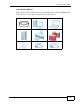
Document Conventions Icons Used in Figures Figures in this User’s Guide may use the following generic icons. The NWA3000-N series AP icon is not an exact representation of your device.
Safety Warnings Safety Warnings • Do NOT use this product near water, for example, in a wet basement or near a swimming pool. • Do NOT expose your device to dampness, dust or corrosive liquids. • Do NOT store things on the device. • Do NOT install, use, or service this device during a thunderstorm. There is a remote risk of electric shock from lightning. • Connect ONLY suitable accessories to the device. • ONLY qualified service personnel should service or disassemble this device.
Table of Contents Table of Contents About This User's Guide .......................................................................................................... 3 Document Conventions............................................................................................................ 4 Safety Warnings........................................................................................................................ 6 Table of Contents........................................................
Table of Contents 3.1 Overview .............................................................................................................................. 49 3.2 Object-based Configuration ................................................................................................. 49 3.3 Feature Configuration Overview .......................................................................................... 49 3.3.1 Feature ...........................................................................
Table of Contents Chapter 6 Monitor................................................................................................................................. 83 6.1 Overview .............................................................................................................................. 83 6.1.1 What You Can Do in this Chapter .............................................................................. 83 6.2 What You Need to Know ......................................................
Table of Contents 9.3.1 Edit AP List ...............................................................................................................115 9.4 MON Mode .........................................................................................................................116 9.4.1 Add/Edit Rogue/Friendly List .....................................................................................118 9.5 Load Balancing ..............................................................................
Table of Contents 13.1 Overview .......................................................................................................................... 165 13.1.1 What You Can Do in this Chapter .......................................................................... 165 13.1.2 What You Need To Know ....................................................................................... 165 13.2 MON Profile ................................................................................................
Table of Contents 15.7 Telnet .............................................................................................................................. 214 15.8 FTP ................................................................................................................................. 215 15.9 SNMP ............................................................................................................................. 217 15.9.1 Supported MIBs .............................................
Table of Contents Chapter 19 Reboot.................................................................................................................................... 263 19.1 Overview .......................................................................................................................... 263 19.1.1 What You Need To Know ....................................................................................... 263 19.2 Reboot .................................................................
Table of Contents 14 NWA3000-N Series User’s Guide
P ART I User’s Guide 15
CHAPTER 1 Introduction 1.1 Overview Your NWA3000-N series AP’s business-class reliability, SMB features, and centralized wireless management make it ideally suited for advanced service delivery in mission-critical networks. The NWA3000-N series AP provides secure mobility across the 2.4GHz and 5GHz spectrums and the IEEE 802.11n standard’s high bandwidth to support high-performance applications. It uses Multiple BSSID and VLAN to provide up to eight simultaneous independent virtual APs.
Chapter 1 Introduction 1.2 Applications for the NWA3000-N series AP The NWA3000-N series AP can be configured to use the following operating modes • Bridge / Repeater • AP + Bridge • MBSSID Applications for each operating mode are shown below. Note: A different channel should be configured for each WLAN interface to reduce the effects of radio interference. 1.2.1 Bridge / Repeater The NWA3000-N series AP can act as a wireless network bridge and establish wireless links with other APs.
Chapter 1 Introduction At the time of writing, WDS security is compatible with other ZyXEL access points only. Refer to your other access point’s documentation for details.
Chapter 1 Introduction 1.2.1.1 Bridge / Repeater Mode Example In the example below, when both NWA3000-N series APs are in Bridge/Repeater mode, they form a WDS (Wireless Distribution System) allowing the computers in LAN 1 to connect to the computers in LAN 2. Figure 3 Bridging Example Be careful to avoid bridge loops when you enable bridging in the NWA3000-N series AP.
Chapter 1 Introduction • If two or more NWA3000-N series APs (in bridge mode) are connected to the same hub. Figure 4 Bridge Loop: Two Bridges Connected to Hub • If your NWA3000-N series AP (in bridge mode) is connected to a wired LAN while communicating with another wireless bridge that is also connected to the same wired LAN.
Chapter 1 Introduction 1.2.2 AP + Bridge In AP + Bridge mode, the NWA3000-N series AP supports both AP and bridge connection at the same time. In the figure below, A and B use X as an AP to access the wired network, while X and Y communicate in bridge mode. When the NWA3000-N series AP is in AP + Bridge mode, security between APs (WDS) is independent of the security between the wireless stations and the AP. If you do not enable WDS security, traffic between APs is not encrypted.
Chapter 1 Introduction NWA3000-N series AP provides multiple virtual APs, each forming its own BSS and using its own individual SSID profile. You can assign different wireless and security settings to each SSID profile. This allows you to compartmentalize groups of users, set varying access privileges, and prioritize network traffic to and from certain BSSs. To the wireless clients in the network, each SSID appears to be a different access point.
Chapter 1 Introduction The following figure illustrates a CAPWAP wireless network. The user (U) configures the controller AP (C), which then automatically updates the configurations of the managed APs (M1 ~ M4). Figure 7 CAPWAP Network Example U C M1 M2 M3 M4 1.4 Ways to Manage the NWA3000-N series AP You can use the following ways to manage the NWA3000-N series AP. Web Configurator The Web Configurator allows easy NWA3000-N series AP setup and management using an Internet browser.
Chapter 1 Introduction Console Port You can use the console port to manage the NWA3000-N series AP using CLI commands. See the Command Reference Guide for more information about the CLI. The default settings for the console port are as follows. Table 1 Console Port Default Settings SETTING VALUE Speed 115200 bps Data Bits 8 Parity None Stop Bit 1 Flow Control Off File Transfer Protocol (FTP) This protocol can be used for firmware upgrades and configuration backup and restore.
Chapter 1 Introduction • Back up the configuration (and make sure you know how to restore it). Restoring an earlier working configuration may be useful if the device becomes unstable or even crashes. If you forget your password, you will have to reset the NWA3000-N series AP to its factory default settings. If you backed up an earlier configuration file, you won’t have to totally re-configure the NWA3000-N series AP; you can simply restore your last configuration. 1.
Chapter 1 Introduction 1.7 LEDs The following are the LED descriptions for your NWA3000-N series AP. Figure 8 LEDs Table 2 LEDs LABEL COLOR WLAN Green STATUS On Blinking Off NWA3000-N Series User’s Guide DESCRIPTION The wireless LAN is active. The wireless LAN is active, and transmitting or receiving data. The wireless LAN is not active.
Chapter 1 Introduction Table 2 LEDs (continued) LABEL COLOR STATUS DESCRIPTION ETHERNET Green On The NWA3000-N series AP has a 10/100 Mbps Ethernet connection. Blinking The NWA3000-N series AP has a 10/100 Mbps Ethernet connection and is sending or receiving data. On The NWA3000-N series AP has a 1000 Mbps Ethernet connection. Blinking The NWA3000-N series AP has a 1000 Mbps Ethernet connection and is sending/receiving data. Off The NWA3000-N series AP does not have an Ethernet connection.
Chapter 1 Introduction 1.8 Starting and Stopping the NWA3000-N series AP Here are some of the ways to start and stop the NWA3000-N series AP. Always use Maintenance > Shutdown or the shutdown command before you turn off the NWA3000-N series AP or remove the power. Not doing so can cause the firmware to become corrupt. Table 3 Starting and Stopping the NWA3000-N series AP METHOD DESCRIPTION Turning on the power A cold start occurs when you turn on the power to the NWA3000-N series AP.
Chapter 1 Introduction 30 NWA3000-N Series User’s Guide
CHAPTER 2 The Web Configurator 2.1 Overview The NWA3000-N series AP Web Configurator allows easy management using an Internet browser. In order to use the Web Configurator, you must: • Use Internet Explorer 7.0 and later or Firefox 1.5 and later • Allow pop-up windows • Enable JavaScript (enabled by default) • Enable Java permissions (enabled by default) • Enable cookies The recommended screen resolution is 1024 x 768 pixels and higher.
Chapter 2 The Web Configurator 2.2 Access 1 Make sure your NWA3000-N series AP hardware is properly connected. See the Quick Start Guide. 2 Browse to https://192.168.1.2. The Login screen appears. 3 Enter the user name (default: “admin”) and password (default: “1234”). 4 Click Login. If you logged in using the default user name and password, the Update Admin Info screen appears. Otherwise, the dashboard appears.
Chapter 2 The Web Configurator 2.
Chapter 2 The Web Configurator 2.3.1 Title Bar The title bar provides some useful links that always appear over the screens below, regardless of how deep into the Web Configurator you navigate. Figure 10 Title Bar The icons provide the following functions. Table 4 Title Bar: Web Configurator Icons LABEL DESCRIPTION Logout Click this to log out of the Web Configurator. Help Click this to open the help page for the current screen.
Chapter 2 The Web Configurator 2.3.2.1 Dashboard The dashboard displays general device information, system status, system resource usage, and interface status in widgets that you can re-arrange to suit your needs. For details on the Dashboard’s features, see Chapter 5 on page 75. 2.3.2.2 Monitor Menu The monitor menu screens display status and statistics information.
Chapter 2 The Web Configurator Table 6 Configuration Menu Screens Summary (continued) FOLDER OR LINK TAB FUNCTION Controller Configure how the NWA3000-N series AP handles APs that newly connect to the network. This is available when the NWA3000-N series AP is in controller mode. AP Management Edit wireless AP information, remove APs, and reboot them. MON Mode Configure how the NWA3000-N series AP monitors for rogue APs.
Chapter 2 The Web Configurator Table 6 Configuration Menu Screens Summary (continued) FOLDER OR LINK TAB FUNCTION FTP Configure FTP server settings. SNMP Configure SNMP communities and services. Auth. Server Configure settings for the NWA3000-N series AP’s built-in authentication server. Log & Report Email Daily Report Configure where and how to send daily reports and what reports to send. Log Setting Configure the system log, e-mail logs, and remote syslog servers. 2.3.2.
Chapter 2 The Web Configurator 2.3.3 Warning Messages Warning messages, such as those resulting from misconfiguration, display in a popup window. Figure 12 Warning Message 2.3.4 Site Map Click Site MAP to see an overview of links to the Web Configurator screens. Click a screen’s link to go to that screen. Figure 13 Site Map 2.3.5 Object Reference Click Object Reference to open the Object Reference screen.
Chapter 2 The Web Configurator settings reference the object. The following example shows which configuration settings reference the ldap-users user object (in this case the first firewall rule). Figure 14 Object Reference The fields vary with the type of object. The following table describes labels that can appear in this screen. Table 8 Object References LABEL DESCRIPTION Object Name This identifies the object for which the configuration settings that use it are displayed.
Chapter 2 The Web Configurator 2.3.5.1 CLI Messages Click CLI to look at the CLI commands sent by the Web Configurator. These commands appear in a popup window, such as the following. Figure 15 CLI Messages Click Clear to remove the currently displayed information. Note: See the Command Reference Guide for information about the commands. 2.3.5.2 Console The Console allows you to use CLI commands from directly within the Web Configurator rather than having to use a separate terminal program.
Chapter 2 The Web Configurator Note: To view the functions in the Web Configurator user interface that correspond directly to specific NWA3000-N series AP CLI commands, use the CLI Messages window (see Section 2.3.5.1 on page 40) in tandem with this one. Figure 16 Console The following table describes the elements in this screen. Table 9 Console LABEL DESCRIPTION Command Line Enter commands for the device that you are currently logged into here.
Chapter 2 The Web Configurator Table 9 Console (continued) LABEL DESCRIPTION Connection Status This displays the connection status of the account currently logged in. If you are logged in and connected, then this displays ‘Connected’. If you lose the connection, get disconnected, or logout, then this displays ‘Not Connected’. Tx/RX Activity Monitor This displays the current upload / download activity. The faster and more frequently an LED flashes, the faster the data connection.
Chapter 2 The Web Configurator 3 Next, enter the User Name of the account being used to log into your target device and then click OK. 4 You may be prompted to authenticate your account password, depending on the type of device that you are logging into. Enter the password and click OK. 5 If your login is successful, the command line appears and the status bar at the bottom of the Console updates to reflect your connection state.
Chapter 2 The Web Configurator 2.3.6 Tables and Lists The Web Configurator tables and lists are quite flexible and provide several options for how to display their entries. 2.3.6.1 Manipulating Table Display Here are some of the ways you can manipulate the Web Configurator tables. 1 Click a column heading to sort the table’s entries according to that column’s criteria. 2 Click the down arrow next to a column heading for more options about how to display the entries.
Chapter 2 The Web Configurator 3 Select a column heading cell’s right border and drag to re-size the column. 4 Select a column heading and drag and drop it to change the column order. A green check mark displays next to the column’s title when you drag the column to a valid new location. 5 Use the icons and fields at the bottom of the table to navigate to different pages of entries and control how many entries display at a time.
Chapter 2 The Web Configurator 2.3.6.2 Working with Table Entries The tables have icons for working with table entries. A sample is shown next. You can often use the [Shift] or [Ctrl] key to select multiple entries to remove, activate, or deactivate. Table 10 Common Table Icons Here are descriptions for the most common table icons. Table 11 Common Table Icons 46 LABEL DESCRIPTION Add Click this to create a new entry.
Chapter 2 The Web Configurator 2.3.6.3 Working with Lists When a list of available entries displays next to a list of selected entries, you can often just double-click an entry to move it from one list to the other. In some lists you can also use the [Shift] or [Ctrl] key to select multiple entries, and then use the arrow button to move them to the other list.
Chapter 2 The Web Configurator 48 NWA3000-N Series User’s Guide
CHAPTER 3 Configuration Basics 3.1 Overview This section provides information to help you configure the NWA3000-N series AP effectively. Some of it is helpful when you are just getting started. Some of it is provided for your reference when you configure various features in the NWA3000N series AP. 3.2 Object-based Configuration The NWA3000-N series AP stores information or settings as objects. You use these objects to configure many of the NWA3000-N series AP’s features and settings.
Chapter 3 Configuration Basics 3.3.1 Feature This provides a brief description. See the appropriate chapter(s) in this User’s Guide for more information about any feature. MENU ITEM(S) This shows you the sequence of menu items and tabs you should click to find the main screen(s) for this feature. See the web help or the related User’s Guide chapter for information about each screen. These are other features you should configure before you configure the main screen(s) for this feature.
Chapter 3 Configuration Basics PREREQUISITES Radio profiles, SSID profiles, and security profiles 3.3.5 Device HA To increase network reliability, device HA lets a backup NWA3000-N series AP automatically take over if a master NWA3000-N series AP fails. Device HA is available when the NWA3000-N series AP is in controller mode. MENU ITEM(S) Configuration > Device HA PREREQUISITES Interfaces (with a static IP address), to-NWA3000-N series AP firewall 3.
Chapter 3 Configuration Basics 3.4.2 AP Profile Use these screens to configure preset profiles for the Access Points (APs) connected to your NWA3000-N series AP’s wireless network. Table 14 AP Profile Types TYPE ABILITIES Radio Create radio profiles for the APs on your network. SSID Create SSID profiles for the APs on your network. Security Create security profiles for the APs on your network. MAC Filtering Create MAC filtering profiles for the APs on your network. 3.4.
Chapter 3 Configuration Basics 3.5.2 Logs and Reports The NWA3000-N series AP provides a system log, offers two e-mail profiles to which to send log messages, and sends information to four syslog servers. It can also e-mail you statistical reports on a daily basis. MENU ITEM(S) Configuration > Log & Report 3.5.3 File Manager Use these screens to upload, download, delete, or run scripts of CLI commands. You can manage: • Configuration files.
Chapter 3 Configuration Basics 54 NWA3000-N Series User’s Guide
CHAPTER 4 Tutorials 4.1 Sample Network Setup This tutorial shows you how to use CAPWAP to have one NWA3000-N series AP control other NWA3000-N series APs to create a wireless network that allows two types of connections: staff and guest. Staff connections have full access to the network, while guests are limited to Internet access (DNS, HTTP and HTTPS services).
Chapter 4 Tutorials The following VLAN settings are used in this tutorial: Table 16 Tutorial Topology Summary VLAN VLAN ID IP ADDRESS Management 99 10.10.99.10/24 Staff 101 10.1.101.254/24 Guest 102 10.1.102.254/24 Figure 19 Tutorial Guest VLAN Example vlan 102 Controller vlan 102 Managed APs In this example, the guest VLAN (102) can only access the Internet while the staff VLAN (101) has access to all aspects of the network. 4.1.
Chapter 4 Tutorials 4.1.1.1 Controller 1 Use the Configuration > MGNT MODE screen to set the NWA3000-N series AP to controller mode. 2 The NWA3000-N series AP resets to its default settings for the controller mode including the IP address of 192.168.1.2 and restarts. Wait a short while before you attempt to log in again. 4.1.1.
Chapter 4 Tutorials 1 Open the controller’s Configuration > LAN Setting screen. • IP Address: Enter 10.10.99.10. • Subnet Mask: Enter 255.255.255.0. • Gateway: Enter 10.10.99.10. • Management VLAN ID: Enter ‘99’ as the VLAN ID tag. • Click Apply to save these changes. 2 Configure your DHCP server with the controller’s IP address configured as option 138 so the managed NWA3000-N series APs can get the controller’s IP address from it. See Chapter 7 on page 103 for details. 4.1.
Chapter 4 Tutorials 1 Open the Configuration > System > Auth. Server screen. Turn on the authentication server and select the certificate to use. Click Apply. 2 Open the Configuration > Object > User > User screen and click Add. 3 The Add A User window opens.
Chapter 4 Tutorials 4 3a User Name: Enter ‘guest1’. 3b User Type: User 3c Password: Enter ‘guest1’, and re-enter it in the Retype field to confirm. 3d Click OK to save these settings. Repeat steps 2 and 3 to create accounts for the staff members. 4.1.4 Create the AP Profiles (staff, guest) This section shows you how to configure the Access Point (AP) profiles that will be used by your APs once they are connected to the network.
Chapter 4 Tutorials 2 The Add Security Profile window opens. 2a 2b Security Mode: Select wpa2 from the list of available wireless security encryption methods. 2c Under Security Mode, select 802.1X then set the Radius Server Type to Internal. 2d 3 Profile Name: Enter wap2. Click OK. Next, open the Configuration > Object > AP Profile > SSID > SSID List screen and click the Add button.
Chapter 4 Tutorials 4 The Add SSID Profile window opens. 4a 62 Profile Name: Enter ‘staff’. 4b SSID: Enter ‘staff’. This is the wireless network name that appears when wireless clients are looking for networks to join. 4c Security Profile: Select wpa2 from the list. This is the security profile created in step 2. 4d QoS: Select WMM. 4e VLAN ID: Enter ‘101’. 4f Turn on intra-BSS traffic blocking. 4g Click OK to save these settings.
Chapter 4 Tutorials 7 The Edit Radio Profile window opens. 7a 7b 7c Activate: Select this to make the radio profile active. MBSSID Settings: Select an entry to change it to a drop-down list. Set #1, to the staff SSID profile and #2 to the guest SSID profile. These are the two profiles you created in steps 3 to 5 of this procedure. Click OK to save these settings. 4.
Chapter 4 Tutorials In this example, an employee illicitly connects his own AP (RG) to the network that the NWA3000-N series AP manages. While not necessarily a malicious act, it can nonetheless have severe security consequences on the network.
Chapter 4 Tutorials Here, an attacker sets up a rogue AP (RG) outside the network, which he uses in an attempt to mimic an NWA3000-N series AP-controlled SSID in order to capture passwords and other information when authorized wireless clients mistakenly connect to it. Figure 21 Rogue AP Example B This tutorial shows you how to detect rogue APs on your network: 1 Click Configuration > Object > MON Profile to open the MON Profile screen and click the Add button.
Chapter 4 Tutorials 2 Click the Add button. When the Add Mon Profile window opens, configure the following: Activate: Select this to allow your monitor APs to use this profile. Profile Name: For the purposes of this tutorial set this to ‘Monitor01’. Channel Dwell Time: Leave this as the default 100 milliseconds. This field is the number of milliseconds that the monitor AP scans each channel before moving on to the next. Scan Channel Mode: Set this to auto to automatically scan channels in the area.
Chapter 4 Tutorials 5 Select an AP and click Edit. When the Edit AP List window opens, configure the following: Radio 1 OP Mode: Set this to MON Mode to turn the AP into a rogue AP monitoring device. Radio 1 Profile: Select your newly created ‘Monitor01’ profile from the list. 6 Click OK to save your changes. See also: Chapter 6 on page 83 and Chapter 13 on page 165. 4.2.
Chapter 4 Tutorials broadcasting dummy packets so that it cannot makes connections with employee clients and capture data from them. Figure 22 Containing a Rogue AP This tutorial shows you how to quarantine a rogue AP on your network: 1 68 Click Configuration > Wireless > MON Mode.
Chapter 4 Tutorials 2 Click the Add button. When the Edit Rogue/Friendly AP List opens, paste the MAC address copied from the other screen in the corresponding field, set its Role as Rogue AP and then click OK to save your changes. 3 The new rogue AP appears in the Rogue/Friendly AP List. Select it, then click the Containment button to quarantine it away from the rest of the network. 4.3 Load Balancing When your AP becomes overloaded, there are two basic responses it can take.
Chapter 4 Tutorials 1 Click Configuration > Wireless > Load Balancing. 2 Select Enable Load Balancing to turn on this feature. 3 Set the Mode. If you choose By Station Number, then enter the Max Station Number in the available field. This balances network traffic based on the number of specified stations downstream of the NWA3000-N series AP. If you choose By Traffic Level, then enter the traffic threshold at which the NWA3000-N series AP starts balancing connected stations.
Chapter 4 Tutorials 1 Click Configuration > Wireless > DCS. 2 Select Enable Dynamic Channel Selection to turn on this feature. 3 Set the DCS Time Interval. This is how often the NWA3000-N series AP surveys the other APs within its broadcast radius. If you place your APs in an area with a large number of competing APs, set this number lower to ensure that your device can adjust quickly changing conditions. 4 Select DCS Sensitivity Level.
Chapter 4 Tutorials 72 NWA3000-N Series User’s Guide
P ART II Technical Reference 73
CHAPTER 5 Dashboard 5.1 Overview Use the Dashboard screens to check status information about the NWA3000-N series AP. 5.1.1 What You Can Do in this Chapter • The main Dashboard screen (Section 5.2 on page 76) displays the NWA3000-N series AP’s general device information, system status, system resource usage, and interface status. You can also display other status screens for more information.
Chapter 5 Dashboard 5.2 Dashboard This screen is the first thing you see when you log into the NWA3000-N series AP. It also appears every time you click the Dashboard icon in the navigation panel. The Dashboard displays general device information, system status, system resource usage, and interface status in widgets that you can re-arrange to suit your needs. You can also collapse, refresh, and close individual widgets.
Chapter 5 Dashboard Table 17 Dashboard (continued) LABEL DESCRIPTION System Name This field displays the name used to identify the NWA3000-N series AP on any network. Click the icon to open the screen where you can change it. Model Name This field displays the model name of this NWA3000-N series AP. Serial Number This field displays the serial number of this NWA3000-N series AP. MAC Address Range This field displays the MAC addresses used by the NWA3000-N series AP.
Chapter 5 Dashboard Table 17 Dashboard (continued) LABEL DESCRIPTION WDS Link Status This section displays information about the WDS settings when the NWA3000-N series AP is in controller mode and configured to use WDS. Radio This field displays which radio the NWA3000-N series AP is configured to use for WDS. Link ID This field displays the name of the bridge connection. Peer MAC Address This field displays the hardware address of the peer device.
Chapter 5 Dashboard Table 17 Dashboard (continued) LABEL DESCRIPTION Name This field displays the name of each interface. Status This field displays the current status of each interface. The possible values depend on what type of interface it is. Inactive - The Ethernet interface is disabled. Down - The Ethernet interface is enabled but not connected. Speed / Duplex - The Ethernet interface is enabled and connected. This field displays the port speed and duplex setting (Full or Half).
Chapter 5 Dashboard Table 17 Dashboard (continued) LABEL DESCRIPTION Radio This indicates the radio number on the NWA3000-N series AP. Band This indicates the wireless frequency band currently being used by the radio. OP Mode This indicates the radio’s operating mode. Operating modes are AP (access point) or MON (monitor). Channel This indicates the channel number the radio is using. Station This displays the number of wireless clients connected to the NWA3000-N series AP. 5.2.
Chapter 5 Dashboard 5.2.2 Memory Usage Use this screen to look at a chart of the NWA3000-N series AP’s recent memory (RAM) usage. To access this screen, click Memory Usage in the dashboard. Figure 25 Dashboard > Memory Usage The following table describes the labels in this screen. Table 19 Dashboard > Memory Usage LABEL DESCRIPTION The y-axis represents the percentage of RAM usage.
Chapter 5 Dashboard 82 NWA3000-N Series User’s Guide
CHAPTER 6 Monitor 6.1 Overview Use the Monitor screens to check status and statistics information. 6.1.1 What You Can Do in this Chapter • The LAN Status screen (Section 6.3 on page 84) displays general LAN interface information and packet statistics. • The LAN Status Graph screen (Section 6.3.1 on page 86) displays a line graph of packet statistics for the NWA3000-N series AP’s physical LAN port. • The AP List screen (Section 6.
Chapter 6 Monitor Rogue AP Rogue APs are wireless access points operating in a network’s coverage area that are not under the control of the network’s administrators, and can open up holes in a network’s security. See Chapter 13 on page 165 for details. Friendly AP Friendly APs are other wireless access points that are detected in your network, as well as any others that you know are not a threat (those from neighboring networks, for example). See Chapter 13 on page 165 for details. 6.
Chapter 6 Monitor Table 20 Monitor > LAN Status (continued) LABEL DESCRIPTION Name This field displays the name of the interface. Status This field displays the current status of the interface: Inactive - The Ethernet interface is disabled. Down - The Ethernet interface is enabled but not connected. Speed / Duplex - The Ethernet interface is enabled and connected. This field displays the port speed and duplex setting (Full or Half).
Chapter 6 Monitor Table 20 Monitor > LAN Status (continued) LABEL DESCRIPTION Collisions This field displays the number of collisions on the physical port since it was last connected. Tx This field displays the transmission speed, in bytes per second, on the physical port in the one-second interval before the screen updated. Rx This field displays the reception speed, in bytes per second, on the physical port in the one-second interval before the screen updated.
Chapter 6 Monitor Table 21 Monitor > LAN Status > Switch to Graphic View (continued) LABEL DESCRIPTION Switch to Grid View Click this to display the port statistics as a table. Kbps The y-axis represents the speed of transmission or reception. time The x-axis shows the time period over which the transmission or reception occurred TX This line represents traffic transmitted from the NWA3000-N series AP on the physical port since it was last connected.
Chapter 6 Monitor The following table describes the labels in this screen. Table 22 Monitor > Wireless > AP Information > AP List LABEL DESCRIPTION Add to Mgnt AP List When the NWA3000-N series AP is in controller mode, it lists the compatible NWA3000-N series APs it detects in this screen. Select an entry where the Status displays an AP icon with a question mark (?) and click this button to have the NWA3000-N series AP manage it.
Chapter 6 Monitor 6.4.1 Station Count of AP Use this screen to look at station statistics for the connected AP. To access this screen, click the More Information button in the AP List screen. Figure 29 Monitor > System Status > AP List > More Information The following table describes the labels in this screen. Table 24 Monitor > System Status > AP List > More Information LABEL DESCRIPTION Station Count The y-axis represents the number of connected stations.
Chapter 6 Monitor connected to the NWA3000-N series AP when it is in controller mode. To access this screen, click Monitor > Wireless > AP Information > Radio List. Figure 30 Monitor > Wireless > AP Information > Radio List (Controller Mode) The following table describes the labels in this screen. Table 25 Monitor > Wireless > AP Information > Radio List 90 LABEL DESCRIPTION More Information Click this to view additional information about the selected radio’s wireless traffic and station count.
Chapter 6 Monitor 6.5.1 AP Mode Radio Information This screen allows you to view a selected radio’s MBSSID details, wireless traffic statistics and station count for the preceding 24 hours. To access this window, click the More Information button in the Radio List Statistics screen.
Chapter 6 Monitor The following table describes the labels in this screen. Table 26 Monitor > Wireless > AP Information > Radio List > More Information LABEL DESCRIPTION MBSSID Detail This list shows information about all the wireless clients that have connected to the specified radio over the preceding 24 hours. # This is the items sequential number in the list. It has no bearing on the actual data in this list. SSID Name This displays an SSID associated with this radio.
Chapter 6 Monitor 6.6 Station List Use this screen to view statistics pertaining to the associated stations (or “wireless clients”). Click Monitor > Wireless > Station Info to access this screen. Figure 32 Monitor > Wireless > Station Info The following table describes the labels in this screen. Table 27 Monitor > Wireless > Station Info LABEL DESCRIPTION # This is the station’s index number in this list. MAC Address This is the station’s MAC address.
Chapter 6 Monitor 6.7 Rogue AP Use this screen to view information about suspected rogue APs. Click Monitor > Wireless > Rogue AP > Detected Device to access this screen. Note: The NWA3000-N series AP or at least one of the APs the NWA3000-N series AP is managing must be set to Monitor mode in order to detect other wireless devices in its vicinity. Figure 33 Monitor > Wireless > Rogue AP The following table describes the labels in this screen.
Chapter 6 Monitor Table 28 Monitor > Wireless > Rogue AP (continued) LABEL DESCRIPTION Last Seen This indicates the last time the device was detected by the NWA3000-N series AP. Refresh Click this to refresh the items displayed on this page. 6.8 Legacy Device Info When the NWA3000-N series AP is in controller mode you can use this screen to configure and maintain a list of compatible legacy (NWA-3000 series) APs. Use the list to link to their Web Configurators.
Chapter 6 Monitor Table 29 Monitor > Wireless > Legacy Device Info (continued) LABEL DESCRIPTION IP This is the IP address of the legacy AP. Description This is manually entered information about the legacy AP represented by this entry. 6.8.1 Legacy Device Info Add or Edit Use this screen to configure an entry for linking to a compatible legacy AP’s Web Configurator. The legacy AP must also be in controller mode.
Chapter 6 Monitor Note: When a log reaches the maximum number of log messages, new log messages automatically overwrite existing log messages, starting with the oldest existing log message first. • For individual log descriptions, see Appendix A on page 285. • For the maximum number of log messages in the NWA3000-N series AP, see Chapter 22 on page 279. Events that generate an alert (as well as a log message) display in red. Regular logs display in black.
Chapter 6 Monitor The following table describes the labels in this screen. Table 31 Monitor > Log > View Log LABEL DESCRIPTION Show Filter / Hide Filter Click this button to show or hide the filter settings. If the filter settings are hidden, the Display, Email Log Now, Refresh, and Clear Log fields are available. If the filter settings are shown, the Display, Priority, Source Address, Destination Address, Service, Keyword, and Search fields are available.
Chapter 6 Monitor Table 31 Monitor > Log > View Log (continued) LABEL DESCRIPTION Message This field displays the reason the log message was generated. The text “[count=x]”, where x is a number, appears at the end of the Message field if log consolidation is turned on and multiple entries were aggregated to generate into this one. Source This field displays the source IP address and the port number in the event that generated the log message.
Chapter 6 Monitor 6.10 View AP Log Use this screen to view a managed AP’s log. Click Monitor > Log > View AP Log to access this screen. Figure 37 Monitor > Log > View AP Log The following table describes the labels in this screen. Table 32 Monitor > Log > View AP Log LABEL DESCRIPTION Show/Hide Filter Click this to show or hide the AP log filter. Select an AP Select an AP from the list to view its log messages. Log Query Status This indicates the current log query status.
Chapter 6 Monitor Table 32 Monitor > Log > View AP Log (continued) LABEL DESCRIPTION Log File Status This indicates the status of the AP’s log messages. Last Log Query Time This indicates the last time the AP was queried for its log messages. Display Select the log file from the specified AP that you want displayed. Note: This criterion only appears when you Show Filter. Priority Select a priority level to use for filtering displayed log messages.
Chapter 6 Monitor Table 32 Monitor > Log > View AP Log (continued) 102 LABEL DESCRIPTION Source This displays the source IP address of the selected log message. Destination This displays the source IP address of the selected log message. Note This displays any notes associated with the selected log message.
CHAPTER 7 Management Mode 7.1 Overview This chapter discusses using the NWA3000-N series AP in management mode, which determines whether the NWA3000-N series AP is used in its default standalone mode, or as part of a Control And Provisioning of Wireless Access Points (CAPWAP) network. 7.2 About CAPWAP The NWA3000-N series AP supports CAPWAP. This is ZyXEL’s implementation of the CAPWAP protocol (RFC 5415). The CAPWAP dataflow is protected by Datagram Transport Layer Security (DTLS).
Chapter 7 Management Mode Note: The NWA3000-N series AP can be a standalone AP (default), a CAPWAP managed AP, or a CAPWAP AP controller. 7.2.1 CAPWAP Discovery and Management The link between CAPWAP-enabled access points proceeds as follows: 1 An AP in managed AP mode joins a wired network (receives a dynamic IP address). 2 The AP sends out a discovery request, looking for an AP in CAPWAP AP controller mode. 3 If there is an AP controller on the network, it receives the discovery request.
Chapter 7 Management Mode • Configure DHCP option 138 with the IP address of the CAPWAP AP controller on your network. DHCP Option 138 allows the CAPWAP management request (from the AP in managed AP mode) to reach the AP controller in a different subnet, as shown in the following figure. Figure 39 CAPWAP and DHCP Option 138 SUBNET 1 SUBNET 2 DHCP SERVER + OPTION 138 CAPWAP TRAFFIC AP CONTROLLER (STATIC IP) MANAGED AP 7.2.
Chapter 7 Management Mode Note: After you change the operation mode, the NWA3000-N series AP resets to its default settings for the mode you set it to, including the IP address of 192.168.1.2. It also backs up its configuration to a xxx-backup.conf file where xxx denotes the mode the NWA3000-N series AP was previously using. Click Configuration > MGNT MODE in the NWA3000-N series AP’s navigation menu. The following screen displays.
CHAPTER 8 LAN Setting 8.1 LAN Setting Overview Use these screens to configure the NWA3000-N series AP’s LAN Ethernet interface including VLAN settings. 8.1.1 What You Can Do in this Chapter • The LAN Setting screens (Section 8.2 on page 108) manage the LAN Ethernet interface including VLAN settings. 8.1.2 What You Need to Know DNS Overview DNS (Domain Name System) is for mapping a domain name to its corresponding IP address and vice versa.
Chapter 8 LAN Setting 8.2 LAN Setting This screen lists every Ethernet interface. To access this screen, click Configuration > LAN Setting.
Chapter 8 LAN Setting Each field is described in the following table. Table 34 Configuration > LAN Setting LABEL DESCRIPTION IP Address Assignment Get Automatically This option appears when the MGNT Mode is set to Stand Alone AP. Select this to make the interface a DHCP client and automatically get the IP address, subnet mask, and gateway address from a DHCP server. Use Fixed IP Address Select this if you want to specify the IP address, subnet mask, and gateway manually.
Chapter 8 LAN Setting Table 34 Configuration > LAN Setting (continued) LABEL DNS Server DESCRIPTION This is the IP address of a DNS server. This field displays N/A if you have the NWA3000-N series AP get a DNS server IP address from the ISP dynamically but the LAN interface is using a static IP address. VLAN Settings Management VLAN ID Enter a VLAN ID for the NWA3000-N series AP.
CHAPTER 9 Wireless 9.1 Overview Use the Wireless screens to configure how the NWA3000-N series AP manages the Access Point that are connected to it. 9.1.1 What You Can Do in this Chapter • The Controller screen (Section 9.2 on page 112) sets how the NWA3000-N series AP allows new APs to connect to the network. This is available when the NWA3000-N series AP is in controller mode. • The AP Management screen (Section 9.
Chapter 9 Wireless Load Balancing (Wireless) Wireless load balancing is the process where you limit the number of connections allowed on an wireless access point (AP) or you limit the amount of wireless traffic transmitted and received on it so the AP does not become overloaded. 9.2 Controller Use this screen to set how the NWA3000-N series AP allows new APs to connect to the network. This is available when the NWA3000-N series AP is in controller mode.
Chapter 9 Wireless 9.3 AP Management Use this screen to manage all of the APs connected to the NWA3000-N series AP. Click Configuration > Wireless > AP Management to access this screen. This screen manages the NWA3000-N series AP’s general wireless settings if it is in standalone mode or the general wireless settings of all of the NWA3000-N series AP’s managed APs if the NWA3000-N series AP is in controller mode.
Chapter 9 Wireless Figure 45 Configuration > Wireless > AP Management (Standalone Mode) The following fields display if the NNWA3000-N series AP is in standalone mode. Table 38 Configuration > Wireless > AP Management (Standalone Mode) 114 LABEL DESCRIPTION Model This field displays the AP’s hardware model information. It displays “N/A” (not applicable) only when the AP disconnects from the NWA3000-N series AP and the information is unavailable as a result.
Chapter 9 Wireless 9.3.1 Edit AP List Select an AP and click the Edit button in the Configuration > Wireless > AP Management table to display this screen. Use this screen to set the managed AP’s general wireless settings. Figure 46 Configuration > Wireless > Edit AP List Each field is described in the following table. Table 39 Configuration > Wireless > Edit AP List LABEL DESCRIPTION Create new Object Use this menu to create a new Radio or SSID object to associate with this AP.
Chapter 9 Wireless Table 39 Configuration > Wireless > Edit AP List (continued) LABEL DESCRIPTION Radio 1 OP Mode Select the operating mode for radio 1. AP Mode means the AP can receive connections from wireless clients and pass their data traffic through to the NWA3000-N series AP to be managed (or subsequently passed on to an upstream gateway for managing).
Chapter 9 Wireless Figure 47 Configuration > Wireless > MON Mode Each field is described in the following table. Table 40 Configuration > Wireless > MON Mode LABEL DESCRIPTION General Settings Enable Rogue AP Containment Select this to enable rogue AP containment. Rogue/Friendly AP List Add Click this button to add an AP to the list and assign it either friendly or rogue status. Edit Select an AP in the list to edit and reassign its status. Remove Select an AP in the list to remove.
Chapter 9 Wireless Table 40 Configuration > Wireless > MON Mode (continued) LABEL DESCRIPTION Description This field displays the AP’s description. You can modify this by clicking the Edit button. Importing/Exporting File Path / Browse / Importing These controls allow you to export the current list of rogue and friendly APs or import existing lists. Enter the file name and path of the list you want to import or click the Browse button to locate it.
Chapter 9 Wireless Table 41 Configuration > Wireless > MON Mode > Add/Edit Rogue/Friendly LABEL DESCRIPTION OK Click OK to save your changes back to the NWA3000-N series AP. Cancel Click Cancel to close the window with changes unsaved. 9.5 Load Balancing Use this screen to configure wireless network traffic load balancing between the APs on your network. Click Configuration > Wireless > Load Balancing to access this screen.
Chapter 9 Wireless Table 42 Configuration > Wireless > Load Balancing (continued) LABEL Disassociate station when overloaded DESCRIPTION Select this option to “kick” wireless clients connected to the AP when it becomes overloaded. If you do not enable this option, then the AP simply delays the connection until it can afford the bandwidth it requires, or it shunts the connection to another AP within its broadcast radius.
Chapter 9 Wireless delays the red laptop’s connection until it can afford the bandwidth or the laptop is picked up by a different AP with bandwidth to spare. Figure 50 Delaying a Connection The second response your AP can take is to kick the connections that are pushing it over its balanced bandwidth allotment. Figure 51 Kicking a Connection Connections are kicked based on either idle timeout or signal strength.
Chapter 9 Wireless 9.6 DCS Use this screen to configure dynamic radio channel selection. Click Configuration > Wireless > DCS to access this screen. Figure 52 Configuration > Wireless > DCS Each field is described in the following table.
Chapter 9 Wireless Table 43 Configuration > Wireless > DCS (continued) LABEL DESCRIPTION DCS Sensitivity Level Select the AP’s sensitivity level toward other channels. Options are High, Medium, and Low. Generally, as long as the area in which your AP is located has minimal interference from other devices you can set the DCS Sensitivity Level to Low. This means that the AP has a very broad tolerance.
Chapter 9 Wireless Table 43 Configuration > Wireless > DCS (continued) LABEL DESCRIPTION Enable 5-GHz DFS Aware Select this if your APs are operating in an area known to have RADAR devices. This allows the device to downgrade its frequency to below 5 GHz in the event a RADAR signal is detected, thus preventing it from interfering with that signal. Enabling this forces the AP to select a non-DFS channel.
Chapter 9 Wireless Figure 53 An Example Three-Channel Deployment Three channels are situated in such a way as to create almost no interference with one another if used exclusively: 1, 6 and 11. When an AP broadcasts on any of these three channels, it should not interfere with neighboring APs as long as they are also limited to same trio.
Chapter 9 Wireless Load Balancing Because there is a hard upper limit on an AP’s wireless bandwidth, load balancing can be crucial in areas crowded with wireless users. Rather than let every user connect and subsequently dilute the available bandwidth to the point where each connecting device receives a meager trickle, the load balanced AP instead limits the incoming connections as a means to maintain bandwidth integrity.
CHAPTER 10 Device HA 10.1 Overview Device HA is available when the NWA3000-N series AP is in controller mode. Device HA lets a backup NWA3000-N series AP (also in controller mode) automatically take over if the master NWA3000-N series AP fails. Figure 56 Device HA Backup Taking Over for the Master A B In this example, device B is the backup for device A in the event something happens to it and prevents it from managing the wireless network. 10.1.
Chapter 10 Device HA 10.1.2 What You Need to Know The following terms and concepts may help as you read this chapter. Management Access You can configure a separate management IP address for each interface. You can use it to access the NWA3000-N series AP for management whether the NWA3000-N series AP is the master or a backup. The management IP address should be in the same subnet as the interface IP address.
Chapter 10 Device HA 10.2 Device HA General This screen lets you enable or disable device HA, and displays which device HA mode the NWA3000-N series AP is set to use along with a summary of the monitored interfaces. Click Configuration > Device HA > General to display. Figure 57 Configuration > Device HA > General The following table describes the labels in this screen.
Chapter 10 Device HA Table 44 Configuration > Device HA > General (continued) LABEL DESCRIPTION HA Status The text before the slash shows whether the device is configured as the master or the backup role. This text after the slash displays the monitored interface’s status in the virtual router. Active - This interface is up and using the virtual IP address and subnet mask. Stand-By - This interface is a backup interface in the virtual router. It is not using the virtual IP address and subnet mask.
Chapter 10 Device HA 10.3 Active-Passive Mode The Device HA Active-Passive Mode screen lets you configure general activepassive mode device HA settings, view and manage the list of monitored interfaces, and synchronize backup NWA3000-N series APs. To access this screen, click Configuration > Device HA > Active-Passive Mode.
Chapter 10 Device HA The following table describes the labels in this screen. Table 45 Configuration > Device HA > Active-Passive Mode LABEL DESCRIPTION Show / Hide Advanced Settings Click this button to display a greater or lesser number of configuration fields. Device Role Select the device HA role that the NWA3000-N series AP plays in the virtual router. Choices are: Master - This NWA3000-N series AP is the master NWA3000-N series AP in the virtual router.
Chapter 10 Device HA Table 45 Configuration > Device HA > Active-Passive Mode (continued) LABEL DESCRIPTION Monitored Interface Summary This table shows the status of the device HA settings and status of the NWA3000-N series AP’s interfaces. Edit Select an entry and click this to be able to modify it. Activate To turn on an entry, select it and click Activate. Inactivate To turn off an entry, select it and click Inactivate. # This is the entry’s index number in the list.
Chapter 10 Device HA Table 45 Configuration > Device HA > Active-Passive Mode (continued) LABEL DESCRIPTION Password Enter the password used for verification during synchronization. Every NWA3000-N series AP in the virtual router must use the same password. If you leave this field blank in the master NWA3000-N series AP, no backup NWA3000-N series APs can synchronize from it. If you leave this field blank in a backup NWA3000-N series AP, it cannot synchronize from the master NWA3000-N series AP.
Chapter 10 Device HA The following table describes the labels in this screen. Table 46 Device HA > Active-Passive Mode > Edit Monitored Interface LABEL DESCRIPTION Enable Monitored Interface Select this to have device HA monitor the status of this interface’s connection. Interface Name This identifies the interface. Virtual Router IP (VRIP) / Subnet Mask This is the interface’s (static) IP address and subnet mask in the virtual router.
Chapter 10 Device HA Cluster ID You can have multiple NWA3000-N series AP virtual routers on your network. Use a different cluster ID to identify each virtual router. In the following example, NWA3000-N series APs A and B form a virtual router that uses cluster ID 1. NWA3000-N series APs C and D form a virtual router that uses cluster ID 2.
CHAPTER 11 User 11.1 Overview This chapter describes how to set up user accounts and user settings for the NWA3000-N series AP. You can also set up rules that control when users have to log in to the NWA3000-N series AP before the NWA3000-N series AP routes traffic for them. 11.1.1 What You Can Do in this Chapter • The User screen (see Section 11.2 on page 138) provides a summary of all user accounts. • The Setting screen (see Section 11.
Chapter 11 User Table 47 Types of User Accounts (continued) TYPE ABILITIES LOGIN METHOD(S) limited-admin Look at NWA3000-N series AP configuration (web, CLI) WWW, TELNET, SSH, Console Perform basic diagnostics (CLI) Access Users user Used for the embedded RADIUS server and SNMPv3 user access Browse user-mode commands (CLI) Note: The default admin account is always authenticated locally, regardless of the authentication method setting. 11.
Chapter 11 User Table 48 Configuration > Object > User (continued) LABEL DESCRIPTION User Name This field displays the user name of each user. User Type This field displays type of user this account was configured as.
Chapter 11 User To access this screen, go to the User screen, and click Add or Edit. Figure 63 Configuration > User > User > Add/Edit A User The following table describes the labels in this screen. Table 49 Configuration > User > User > Add/Edit A User LABEL DESCRIPTION User Name Type the user name for this user account. You may use 1-31 alphanumeric characters, underscores(_), or dashes (-), but the first character cannot be a number. This value is case-sensitive.
Chapter 11 User Table 49 Configuration > User > User > Add/Edit A User (continued) LABEL DESCRIPTION Lease Time Enter the number of minutes this user has to renew the current session before the user is logged out. You can specify 1 to 1440 minutes. You can enter 0 to make the number of minutes unlimited. Admin users renew the session every time the main screen refreshes in the Web Configurator.
Chapter 11 User Figure 64 Configuration > Object > User > Setting The following table describes the labels in this screen. Table 50 Configuration > Object > User > Setting LABEL DESCRIPTION User Authentication Timeout Settings 142 Default Authentication Timeout Settings These authentication timeout settings are used by default when you create a new user account. They also control the settings for any existing user accounts that are set to use the default settings.
Chapter 11 User Table 50 Configuration > Object > User > Setting (continued) LABEL User Type DESCRIPTION These are the kinds of user account the NWA3000-N series AP supports.
Chapter 11 User 11.3.1 Edit User Authentication Timeout Settings This screen allows you to set the default authentication timeout settings for the selected type of user account. These default authentication timeout settings also control the settings for any existing user accounts that are set to use the default settings. You can still manually configure any user account’s authentication timeout settings.
Chapter 11 User Table 51 User > Setting > Edit User Authentication Timeout Settings (continued) LABEL DESCRIPTION Reauthentication Time Type the number of minutes this type of user account can be logged into the NWA3000-N series AP in one session before the user has to log in again. You can specify 1 to 1440 minutes. You can enter 0 to make the number of minutes unlimited. Unlike Lease Time, the user has no opportunity to renew the session without logging out.
Chapter 11 User 146 NWA3000-N Series User’s Guide
CHAPTER 12 AP Profile 12.1 Overview This chapter shows you how to configure preset profiles for the Access Points (APs) connected to your NWA3000-N series AP’s wireless network. 12.1.1 What You Can Do in this Chapter • The Radio screen (Section 12.2 on page 149) creates radio configurations that can be used by the APs. • The SSID screen (Section 12.3 on page 154) configures three different types of profiles for your networked APs. 12.1.
Chapter 12 AP Profile • MAC Filtering - This profile provides an additional layer of security for an SSID, allowing you to block access or allow access to that SSID based on wireless client MAC addresses. If a client’s MAC address is on the list, then it is either allowed or denied, depending on how you set up the MAC Filter profile. You can have a maximum of 32 MAC filtering profiles on the NWA3000-N series AP.
Chapter 12 AP Profile 12.2 Radio This screen allows you to create radio profiles for the APs on your network. A radio profile is a list of settings that an NWA3000-N series AP AP can use to configure either one of its two radio transmitters. To access this screen click Configuration > Object > AP Profile. Note: You can have a maximum of 32 radio profiles on the NWA3000-N series AP. Figure 66 Configuration > Object > AP Profile > Radio The following table describes the labels in this screen.
Chapter 12 AP Profile 12.2.1 Add/Edit Radio Profile This screen allows you to create a new radio profile or edit an existing one. To access this screen, click the Add button or select a radio profile from the list and click the Edit button.
Chapter 12 AP Profile The following table describes the labels in this screen. Table 53 Configuration > Object > AP Profile > Add/Edit Profile LABEL DESCRIPTION Hide / Show Click this to hide or show the Advanced Settings in this window. Advanced Settings Create New Object Select an item from this menu to create a new object of that type. Any objects created in this way are automatically linked to this radio profile. General Settings Activate Select this option to make this profile active.
Chapter 12 AP Profile Table 53 Configuration > Object > AP Profile > Add/Edit Profile (continued) LABEL DESCRIPTION Enable A-MPDU Aggregation Select this to enable A-MPDU aggregation. A-MPDU Limit Enter the maximum frame size to be aggregated. A-MPDU Subframe Enter the maximum number of frames to be aggregated each time. Enable AMSDU Aggregation Select this to enable A-MSDU aggregation. A-MSDU Limit Enter the maximum frame size to be aggregated.
Chapter 12 AP Profile Table 53 Configuration > Object > AP Profile > Add/Edit Profile (continued) LABEL DESCRIPTION Rate Configuration This section controls the data rates permitted for clients. For each Rate, select a rate option from its list. The rates are: • • • • WDS Settings Fast Select - Select an 802.11 broadcast frequency to determine the baseline rate configuration. Basic Rate (Mbps) - Set the basic rate configuration in Mbps. Support Rate (Mbps) - Set the support rate configuration in Mbps.
Chapter 12 AP Profile Table 53 Configuration > Object > AP Profile > Add/Edit Profile (continued) LABEL DESCRIPTION Remote Bridge MAC Type the MAC address of the peer device in a valid MAC address format, that is, six hexadecimal character pairs, for example, 12:34:56:78:9a:bc. PSK Type a pre-shared key (PSK) from 8 to 63 case-sensitive ASCII characters (including spaces and symbols). You must also set the peer device to use the same pre-shared key. Each peer device can use a different pre-shared key.
Chapter 12 AP Profile Note: You can have a maximum of 32 SSID profiles on the NWA3000-N series AP. Figure 68 Configuration > Object > AP Profile > SSID List The following table describes the labels in this screen. Table 54 Configuration > Object > AP Profile > SSID List LABEL DESCRIPTION Add Click this to add a new SSID profile. Edit Click this to edit the selected SSID profile. Remove Click this to remove the selected SSID profile.
Chapter 12 AP Profile 12.3.1.1 Add/Edit SSID Profile This screen allows you to create a new SSID profile or edit an existing one. To access this screen, click the Add button or select an SSID profile from the list and click the Edit button. Figure 69 Configuration > Object > AP Profile > Add/Edit SSID Profile The following table describes the labels in this screen.
Chapter 12 AP Profile Table 55 Configuration > Object > AP Profile > Add/Edit SSID Profile (continued) LABEL DESCRIPTION MAC Filtering Profile Select a MAC filtering profile from the list to associate with this SSID. If none exist, you can sue the Create new Object menu to create one. MAC filtering allows you to limit the wireless clients connecting to your network through a particular SSID by wireless client MAC addresses.
Chapter 12 AP Profile Table 55 Configuration > Object > AP Profile > Add/Edit SSID Profile (continued) LABEL DESCRIPTION OK Click OK to save your changes back to the NWA3000-N series AP. Cancel Click Cancel to exit this screen without saving your changes. 12.3.2 Security List This screen allows you to manage wireless security configurations that can be used by your SSIDs. Wireless security is implemented strictly between the AP broadcasting the SSID and the stations that are connected to it.
Chapter 12 AP Profile 12.3.2.1 Add/Edit Security Profile This screen allows you to create a new security profile or edit an existing one. To access this screen, click the Add button or select a security profile from the list and click the Edit button. Note: This screen’s options change based on the Security Mode selected. Only the default screen is displayed here. Figure 71 SSID > Security Profile > Add/Edit Security Profile The following table describes the labels in this screen.
Chapter 12 AP Profile Table 57 SSID > Security Profile > Add/Edit Security Profile (continued) LABEL DESCRIPTION Primary / Secondary Accounting Server Activate Select the check box to enable user accounting through an external authentication server. Accounting Server IP Address Enter the IP address of the external accounting server in dotted decimal notation. Accounting Server Port Enter the port number of the external accounting server. The default port number is 1813.
Chapter 12 AP Profile Table 57 SSID > Security Profile > Add/Edit Security Profile (continued) LABEL DESCRIPTION Cipher Type Select an encryption cipher type from the list. • • • auto - This automatically chooses the best available cipher based on the cipher in use by the wireless client that is attempting to make a connection. tkip - This is the Temporal Key Integrity Protocol encryption method added later to the WEP encryption protocol to further secure. Not all wireless clients may support this.
Chapter 12 AP Profile Table 58 Configuration > Object > AP Profile > SSID > MAC Filter List (continued) LABEL DESCRIPTION Object Reference Click this to view which other objects are linked to the selected MAC filtering profile (for example, SSID profile). # This field is a sequential value, and it is not associated with a specific user. Profile Name This field indicates the name assigned to the MAC filtering profile. Filter Action This field indicates this profile’s filter action (if any). 12.3.
Chapter 12 AP Profile Table 59 SSID > MAC Filter List > Add/Edit MAC Filter Profile (continued) LABEL DESCRIPTION Edit Click this to edit the selected MAC address in the profile’s list. Remove Click this to remove the selected MAC address from the profile’s list. # This field is a sequential value, and it is not associated with a specific user. MAC This field specifies a MAC address associated with this profile.
Chapter 12 AP Profile 164 NWA3000-N Series User’s Guide
CHAPTER 13 MON Profile 13.1 Overview This screen allows you to set up monitor mode configurations that allow your connected APs to scan for other wireless devices in the vicinity. Once detected, you can use the MON Mode screen (Chapter 9 on page 111) to classify them as either rogue or friendly and then manage them accordingly. 13.1.1 What You Can Do in this Chapter The MON Profile screen (Section 13.2 on page 166) creates preset monitor mode configurations that can be used by the APs. 13.1.
Chapter 13 MON Profile 13.2 MON Profile This screen allows you to create monitor mode configurations that can be used by the APs. To access this screen, login to the Web Configurator, and click Configuration > Object > MON Profile. Figure 74 Configuration > Object > MON Profile The following table describes the labels in this screen. Table 60 Configuration > Object > MON Profile 166 LABEL DESCRIPTION Add Click this to add a new monitor mode profile.
Chapter 13 MON Profile 13.2.1 Add/Edit MON Profile This screen allows you to create a new monitor mode profile or edit an existing one. To access this screen, click the Add button or select and existing monitor mode profile and click the Edit button. Figure 75 Configuration > Object > MON Profile > Add/Edit MON Profile The following table describes the labels in this screen.
Chapter 13 MON Profile Table 61 Configuration > Object > MON Profile > Add/Edit MON Profile (continued) LABEL DESCRIPTION Set Scan Channel List (2.4 G) Move a channel from the Available channels column to the Channels selected column to have the APs using this profile scan that channel when Scan Channel Mode is set to manual. These channels are limited to the 2.4 GHz range (802.11 b/g/n).
Chapter 13 MON Profile In the example above, a corporate network’s security is compromised by a rogue AP (RG) set up by an employee at his workstation in order to allow him to connect his notebook computer wirelessly (A). The company’s legitimate wireless network (the dashed ellipse B) is well-secured, but the rogue AP uses inferior security that is easily broken by an attacker (X) running readily available encryption-cracking software.
Chapter 13 MON Profile 170 NWA3000-N Series User’s Guide
CHAPTER 14 Certificates 14.1 Overview The NWA3000-N series AP can use certificates (also called digital IDs) to authenticate users. Certificates are based on public-private key pairs. A certificate contains the certificate owner’s identity and public key. Certificates provide a way to exchange public keys for use in authentication. 14.1.1 What You Can Do in this Chapter • The My Certificate screens (Section 14.
Chapter 14 Certificates This process works as follows: 1 Tim wants to send a message to Jenny. He needs her to be sure that it comes from him, and that the message content has not been altered by anyone else along the way. Tim generates a public key pair (one public key and one private key). 2 Tim keeps the private key and makes the public key openly available. This means that anyone who receives a message seeming to come from Tim can read it and verify whether it is really from him or not.
Chapter 14 Certificates • Key distribution is simple and very secure since you can freely distribute public keys and you never need to transmit private keys. Self-signed Certificates You can have the NWA3000-N series AP act as a certification authority and sign its own certificates. Factory Default Certificate The NWA3000-N series AP generates its own unique self-signed certificate when you first turn it on. This certificate is referred to in the GUI as the factory default certificate.
Chapter 14 Certificates MD5 or SHA1 algorithm. The following procedure describes how to check a certificate’s fingerprint to verify that you have the actual certificate. 174 1 Browse to where you have the certificate saved on your computer. 2 Make sure that the certificate has a “.cer” or “.crt” file name extension. 3 Double-click the certificate’s icon to open the Certificate window. Click the Details tab and scroll down to the Thumbprint Algorithm and Thumbprint fields.
Chapter 14 Certificates 14.2 My Certificates Click Configuration > Object > Certificate > My Certificates to open this screen. This is the NWA3000-N series AP’s summary list of certificates and certification requests. Figure 77 Configuration > Object > Certificate > My Certificates The following table describes the labels in this screen.
Chapter 14 Certificates Table 62 Configuration > Object > Certificate > My Certificates (continued) LABEL DESCRIPTION Type This field displays what kind of certificate this is. REQ represents a certification request and is not yet a valid certificate. Send a certification request to a certification authority, which then issues a certificate. Use the My Certificate Import screen to import the certificate and replace the request. SELF represents a self-signed certificate.
Chapter 14 Certificates 14.2.1 Add My Certificates Click Configuration > Object > Certificate > My Certificates and then the Add icon to open the My Certificates Add screen. Use this screen to have the NWA3000-N series AP create a self-signed certificate, enroll a certificate with a certification authority or generate a certification request.
Chapter 14 Certificates The following table describes the labels in this screen. Table 63 Configuration > Object > Certificate > My Certificates > Add LABEL DESCRIPTION Name Type a name to identify this certificate. You can use up to 31 alphanumeric and ;‘~!@#$%^&()_+[]{}’,.=- characters. Subject Information Use these fields to record information that identifies the owner of the certificate.
Chapter 14 Certificates Table 63 Configuration > Object > Certificate > My Certificates > Add (continued) LABEL DESCRIPTION Create a certification request and save it locally for later manual enrollment Select this to have the NWA3000-N series AP generate and store a request for a certificate. Use the My Certificate Details screen to view the certification request and copy it to send to the certification authority.
Chapter 14 Certificates Table 63 Configuration > Object > Certificate > My Certificates > Add (continued) LABEL DESCRIPTION Request Authentication When you select Create a certification request and enroll for a certificate immediately online, the certification authority may want you to include a reference number and key to identify you when you send a certification request. Fill in both the Reference Number and the Key fields if your certification authority uses the CMP enrollment protocol.
Chapter 14 Certificates 14.2.2 Edit My Certificates Click Configuration > Object > Certificate > My Certificates and then the Edit icon to open the My Certificate Edit screen. You can use this screen to view in-depth certificate information and change the certificate’s name.
Chapter 14 Certificates The following table describes the labels in this screen. Table 64 Configuration > Object > Certificate > My Certificates > Edit LABEL DESCRIPTION Name This field displays the identifying name of this certificate. You can use up to 31 alphanumeric and ;‘~!@#$%^&()_+[]{}’,.=- characters. Certification Path This field displays for a certificate, not a certification request.
Chapter 14 Certificates Table 64 Configuration > Object > Certificate > My Certificates > Edit LABEL DESCRIPTION Key Algorithm This field displays the type of algorithm that was used to generate the certificate’s key pair (the NWA3000-N series AP uses RSA encryption) and the length of the key set in bits (1024 bits for example). Subject Alternative Name This field displays the certificate owner‘s IP address (IP), domain name (DNS) or e-mail address (EMAIL).
Chapter 14 Certificates Table 64 Configuration > Object > Certificate > My Certificates > Edit LABEL DESCRIPTION OK Click OK to save your changes back to the NWA3000-N series AP. You can only change the name. Cancel Click Cancel to quit and return to the My Certificates screen. 14.2.3 Import Certificates Click Configuration > Object > Certificate > My Certificates > Import to open the My Certificate Import screen.
Chapter 14 Certificates Table 65 Configuration > Object > Certificate > My Certificates > Import (continued) LABEL DESCRIPTION Password This field only applies when you import a binary PKCS#12 format file. Type the file’s password that was created when the PKCS #12 file was exported. OK Click OK to save the certificate on the NWA3000-N series AP. Cancel Click Cancel to quit and return to the My Certificates screen. 14.
Chapter 14 Certificates Table 66 Configuration > Object > Certificate > Trusted Certificates (continued) 186 LABEL DESCRIPTION Object Reference You cannot delete certificates that any of the NWA3000-N series AP’s features are configured to use. Select an entry and click Object References to open a screen that shows which settings use the entry. # This field displays the certificate index number. The certificates are listed in alphabetical order.
Chapter 14 Certificates 14.3.1 Edit Trusted Certificates Click Configuration > Object > Certificate > Trusted Certificates and then a certificate’s Edit icon to open the Trusted Certificates Edit screen. Use this screen to view in-depth information about the certificate, change the certificate’s name and set whether or not you want the NWA3000-N series AP to check a certification authority’s list of revoked certificates before trusting a certificate issued by the certification authority.
Chapter 14 Certificates The following table describes the labels in this screen. Table 67 Configuration > Object > Certificate > Trusted Certificates > Edit LABEL DESCRIPTION Name This field displays the identifying name of this certificate. You can change the name. You can use up to 31 alphanumeric and ;‘~!@#$%^&()_+[]{}’,.=- characters.
Chapter 14 Certificates Table 67 Configuration > Object > Certificate > Trusted Certificates > Edit LABEL DESCRIPTION Type This field displays general information about the certificate. CA-signed means that a Certification Authority signed the certificate. Self-signed means that the certificate’s owner signed the certificate (not a certification authority). X.509 means that this certificate was created and signed according to the ITU-T X.
Chapter 14 Certificates Table 67 Configuration > Object > Certificate > Trusted Certificates > Edit LABEL DESCRIPTION SHA1 Fingerprint This is the certificate’s message digest that the NWA3000-N series AP calculated using the SHA1 algorithm. You can use this value to verify with the certification authority (over the phone for example) that this is actually their certificate. Certificate This read-only text box displays the certificate or certification request in Privacy Enhanced Mail (PEM) format.
Chapter 14 Certificates The following table describes the labels in this screen. Table 68 Configuration > Object > Certificate > Trusted Certificates > Import LABEL DESCRIPTION File Path Type in the location of the file you want to upload in this field or click Browse to find it. You cannot import a certificate with the same name as a certificate that is already in the NWA3000-N series AP. Browse Click Browse to find the certificate file you want to upload.
Chapter 14 Certificates 192 NWA3000-N Series User’s Guide
CHAPTER 15 System 15.1 Overview Use the system screens to configure general NWA3000-N series AP settings. 15.1.1 What You Can Do in this Chapter • The Host Name screen (Section 15.2 on page 194) configures a unique name for the NWA3000-N series AP in your network. • The Date/Time screen (Section 15.3 on page 194) configures the date and time for the NWA3000-N series AP. • The Console Speed screen (Section 15.
Chapter 15 System 15.2 Host Name A host name is the unique name by which a device is known on a network. Click Configuration > System > Host Name to open this screen. Figure 84 Configuration > System > Host Name The following table describes the labels in this screen. Table 69 Configuration > System > Host Name LABEL DESCRIPTION System Name Choose a descriptive name to identify your NWA3000-N series AP device. This name can be up to 64 alphanumeric characters long.
Chapter 15 System To change your NWA3000-N series AP’s time based on your local time zone and date, click Configuration > System > Date/Time. The screen displays as shown. You can manually set the NWA3000-N series AP’s time and date or have the NWA3000-N series AP get the date and time from a time server. Figure 85 Configuration > System > Date/Time The following table describes the labels in this screen.
Chapter 15 System Table 70 Configuration > System > Date/Time (continued) LABEL DESCRIPTION New Date (yyyy-mm-dd) This field displays the last updated date from the time server or the last date configured manually. When you set Time and Date Setup to Manual, enter the new date in this field and then click Apply. Get from Time Server Select this radio button to have the NWA3000-N series AP get the time and date from the time server you specify below.
Chapter 15 System Table 70 Configuration > System > Date/Time (continued) LABEL DESCRIPTION End Date Configure the day and time when Daylight Saving Time ends if you selected Enable Daylight Saving. The at field uses the 24 hour format. Here are a couple of examples: Daylight Saving Time ends in the United States on the first Sunday of November. Each time zone in the United States stops using Daylight Saving Time at 2 A.M. local time.
Chapter 15 System 15.3.2 Time Server Synchronization Click the Synchronize Now button to get the time and date from the time server you specified in the Time Server Address field. When the Loading message appears, you may have to wait up to one minute. Figure 86 Loading The Current Time and Current Date fields will display the appropriate settings if the synchronization is successful. If the synchronization was not successful, a log displays in the View Log screen.
Chapter 15 System 15.4 Console Speed This section shows you how to set the console port speed when you connect to the NWA3000-N series AP via the console port using a terminal emulation program. See Table 1 on page 25 for default console port settings. Click Configuration > System > Console Speed to open this screen. Figure 87 Configuration > System > Console Speed The following table describes the labels in this screen.
Chapter 15 System 15.5 WWW Overview The following figure shows secure and insecure management of the NWA3000-N series AP coming in from the WAN. HTTPS and SSH access are secure. HTTP, and Telnet management access are not secure. Figure 88 Secure and Insecure Service Access From the WAN 15.5.1 Service Access Limitations A service cannot be used to access the NWA3000-N series AP when you have disabled that service in the corresponding screen. 15.5.
Chapter 15 System authentication (one party can identify the other party) and data integrity (you know if data has been changed). It relies upon certificates, public keys, and private keys (see Chapter 14 on page 171 for more information). HTTPS on the NWA3000-N series AP is used so that you can securely access the NWA3000-N series AP using the Web Configurator.
Chapter 15 System Figure 90 Configuration > System > WWW > Service Control The following table describes the labels in this screen. Table 73 Configuration > System > WWW > Service Control LABEL DESCRIPTION HTTPS Enable Select the check box to allow or disallow the computer with the IP address that matches the IP address(es) in the Service Control table to access the NWA3000-N series AP Web Configurator using secure HTTPs connections. Server Port The HTTPS server listens on port 443 by default.
Chapter 15 System Table 73 Configuration > System > WWW > Service Control (continued) LABEL DESCRIPTION Server Port You may change the server port number for a service if needed, however you must use the same port number in order to use that service to access the NWA3000-N series AP. Apply Click Apply to save your changes back to the NWA3000-N series AP. Reset Click Reset to return the screen to its last-saved settings. 15.5.
Chapter 15 System 15.5.5.2 Avoiding Browser Warning Messages Here are the main reasons your browser displays warnings about the NWA3000-N series AP’s HTTPS server certificate and what you can do to avoid seeing the warnings: • The issuing certificate authority of the NWA3000-N series AP’s HTTPS server certificate is not one of the browser’s trusted certificate authorities.
Chapter 15 System Apply for a certificate from a Certification Authority (CA) that is trusted by the NWA3000-N series AP (see the NWA3000-N series AP’s Trusted CA Web Configurator screen). Figure 93 Trusted Certificates The CA sends you a package containing the CA’s trusted certificate(s), your personal certificate(s) and a password to install the personal certificate(s). 15.5.5.
Chapter 15 System 2 Click Install Certificate and follow the wizard as shown earlier in this appendix. 15.5.5.6 Installing a Personal Certificate You need a password in advance. The CA may issue the password or you may have to specify it during the enrollment. Double-click the personal certificate given to you by the CA to produce a screen similar to the one shown next 206 1 Click Next to begin the wizard.
Chapter 15 System 3 Enter the password given to you by the CA. 4 Have the wizard determine where the certificate should be saved on your computer or select Place all certificates in the following store and choose a different location.
Chapter 15 System 5 Click Finish to complete the wizard and begin the import process. 6 You should see the following screen when the certificate is correctly installed on your computer. 15.5.5.7 Using a Certificate When Accessing the NWA3000-N series AP To access the NWA3000-N series AP via HTTPS: 1 208 Enter ‘https://NWA3000-N series AP IP Address/ in your browser’s web address field.
Chapter 15 System 2 When Authenticate Client Certificates is selected on the NWA3000-N series AP, the following screen asks you to select a personal certificate to send to the NWA3000-N series AP. This screen displays even if you only have a single certificate as in the example. 3 You next see the Web Configurator login screen. 15.6 SSH You can use SSH (Secure SHell) to securely access the NWA3000-N series AP’s command line interface.
Chapter 15 System to securely connect to the WAN port of the NWA3000-N series AP (A) for a management session. Figure 94 SSH Communication Over the WAN Example 15.6.1 How SSH Works The following figure is an example of how a secure connection is established between two remote hosts using SSH v1. Figure 95 How SSH v1 Works Example 1 Host Identification The SSH client sends a connection request to the SSH server. The server identifies itself with a host key.
Chapter 15 System 2 Encryption Method Once the identification is verified, both the client and server must agree on the type of encryption method to use. 3 Authentication and Data Transmission After the identification is verified and data encryption activated, a secure tunnel is established between the client and the server. The client then sends its authentication information (user name and password) to the server to log in to the server. 15.6.
Chapter 15 System 15.6.4 Configuring SSH Click Configuration > System > SSH to open the following screen. Use this screen to configure your NWA3000-N series AP’s Secure Shell settings. Note: It is recommended that you disable Telnet and FTP when you configure SSH for secure connections. Figure 96 Configuration > System > SSH The following table describes the labels in this screen.
Chapter 15 System 15.6.5 Examples of Secure Telnet Using SSH This section shows two examples using a command interface and a graphical interface SSH client program to remotely access the NWA3000-N series AP. The configuration and connection steps are similar for most SSH client programs. Refer to your SSH client program user’s guide. 15.6.5.1 Example 1: Microsoft Windows This section describes how to access the NWA3000-N series AP using the Secure Shell Client program.
Chapter 15 System 1 Test whether the SSH service is available on the NWA3000-N series AP. Enter “telnet 192.168.1.2 22” at a terminal prompt and press [ENTER]. The computer attempts to connect to port 22 on the NWA3000-N series AP (using the default IP address of 192.168.1.2). A message displays indicating the SSH protocol version supported by the NWA3000-N series AP. Figure 98 SSH Example 2: Test $ telnet 192.168.1.2 22 Trying 192.168.1.2... Connected to 192.168.1.2. Escape character is '^]'. SSH-1.5-1.
Chapter 15 System Figure 100 Configuration > System > TELNET The following table describes the labels in this screen. Table 75 Configuration > System > TELNET LABEL DESCRIPTION Enable Select the check box to allow or disallow the computer with the IP address that matches the IP address(es) in the Service Control table to access the NWA3000-N series AP CLI using this service.
Chapter 15 System To change your NWA3000-N series AP’s FTP settings, click Configuration > System > FTP tab. The screen appears as shown. Use this screen to specify FTP settings. Figure 101 Configuration > System > FTP The following table describes the labels in this screen.
Chapter 15 System 15.9 SNMP Simple Network Management Protocol is a protocol used for exchanging management information between network devices. Your NWA3000-N series AP supports SNMP agent functionality, which allows a manager station to manage and monitor the NWA3000-N series AP through the network. The NWA3000-N series AP supports SNMP version one (SNMPv1), version two (SNMPv2c), and version three (SNMPv3). The next figure illustrates an SNMP management operation.
Chapter 15 System SNMP itself is a simple request/response protocol based on the manager/agent model. The manager issues a request and the agent returns responses using the following protocol operations: • Get - Allows the manager to retrieve an object variable from the agent. • GetNext - Allows the manager to retrieve the next object variable from a table or list within an agent.
Chapter 15 System 15.9.3 Configuring SNMP To change your NWA3000-N series AP’s SNMP settings, click Configuration > System > SNMP tab. The screen appears as shown. Use this screen to configure your SNMP settings. You can also configure profiles that define allowed SNMPv3 access. Figure 103 Configuration > System > SNMP The following table describes the labels in this screen.
Chapter 15 System Table 78 Configuration > System > SNMP (continued) LABEL DESCRIPTION Set Community Enter the Set community, which is the password for incoming Set requests from the management station. The default is private and allows all requests. SNMPv3 Select this to allow SNMP managers using SNMPv3 to access the NWA3000-N series AP. Add Click this to create a new entry. Select an entry and click Add to create a new entry after the selected entry.
Chapter 15 System The following table describes the labels in this screen. Table 79 Configuration > System > SNMP LABEL DESCRIPTION User Name Select the user name of the user account for which this SNMPv3 user profile is configured. Authentication Select the type of authentication the SNMPv3 user must use to connect to the NWA3000-N series AP using this SNMPv3 user profile. Select NONE to not authenticate the SNMPv3 user.
Chapter 15 System The following figure shows how this is done. Wireless clients make access requests to trusted APs, which relay the requests to the NWA3000-N series AP. Figure 105 Trusted APs Overview RADIUS Server Trusted APs Wireless clients Certificates are used by wireless clients to authenticate the RADIUS server. These are “digital signatures” that identify network devices. Certificates ensure that the clients supply their login details to the correct device.
Chapter 15 System Click Configuration > System > Auth. Server. The following screen displays. Figure 106 Configuration > System > Auth. Server The following table describes the labels in this screen. Table 80 Configuration > System > Auth. Server LABEL DESCRIPTION Enable Authentication Server Select this to have the NWA3000-N series AP use its internal RADIUS server to authenticate wireless clients connecting to trusted APs.
Chapter 15 System Table 80 Configuration > System > Auth. Server (continued) LABEL DESCRIPTION Profile Name This field indicates the name assigned to the trusted AP profile. IP Address This field indicates the IP address of the trusted AP in dotted decimal notation. Mask This field indicates the subnet mask of the trusted AP in dotted decimal notation. The subnet mask indicates what part of the IP address is the same for all computers in the network.
Chapter 15 System Table 81 Configuration > System > Auth. Server (continued) LABEL DESCRIPTION Secret Enter a password (up to 31 alphanumeric characters, no spaces) as the key for encrypting communications between the NWA3000-N series AP and this entry’s AP. The key is not sent over the network. This key must be the same on the NWA3000-N series AP and the AP. Both the NWA3000-N series AP’s IP address and this shared secret must also be configured in the “external RADIUS” server fields of the trusted AP.
Chapter 15 System 226 NWA3000-N Series User’s Guide
CHAPTER 16 Log and Report 16.1 Overview Use the system screens to configure daily reporting and log settings. 16.1.1 What You Can Do In this Chapter • The Email Daily Report screen (Section 16.2 on page 227) configures how and where to send daily reports and what reports to send. • The Log Setting screens (Section 16.3 on page 229) specify which logs are emailed, where they are e-mailed, and how often they are e-mailed. 16.
Chapter 16 Log and Report Click Configuration > Log & Report > Email Daily Report to display the following screen. Configure this screen to have the NWA3000-N series AP e-mail you system statistics every day.
Chapter 16 Log and Report The following table describes the labels in this screen. Table 82 Configuration > Log & Report > Email Daily Report LABEL DESCRIPTION Enable Email Daily Report Select this to send reports by e-mail every day. Mail Server Type the name or IP address of the outgoing SMTP server. Mail Subject Type the subject line for the outgoing e-mail. Select Append system name to add the NWA3000-N series AP’s system name to the subject.
Chapter 16 Log and Report mail profiles are used to mail log messages to the specified destinations, and the other four logs are stored on specified syslog servers. The Log Setting tab also controls what information is saved in each log. For the system log, you can also specify which log messages are e-mailed, where they are e-mailed, and how often they are e-mailed. For alerts, the Log Settings tab controls which events generate alerts and where alerts are e-mailed.
Chapter 16 Log and Report The following table describes the labels in this screen. Table 83 Configuration > Log & Report > Log Setting LABEL DESCRIPTION Edit Double-click an entry or select it and click Edit to open a screen where you can modify the entry’s settings. Activate To turn on an entry, select it and click Activate. Inactivate To turn off an entry, select it and click Inactivate. # This field is a sequential value, and it is not associated with a specific log.
Chapter 16 Log and Report 16.3.2 Edit Log Settings This screen controls the detailed settings for each log in the system log (which includes the e-mail profiles). Go to the Log Settings Summary screen and click the system log Edit icon.
Chapter 16 Log and Report The following table describes the labels in this screen. Table 84 Configuration > Log & Report > Log Setting > Edit LABEL DESCRIPTION E-Mail Server 1/2 Active Select this to send log messages and alerts according to the information in this section. You specify what kinds of log messages are included in log information and what kinds of log messages are included in alerts in the Active Log and Alert section. Mail Server Type the name or IP address of the outgoing SMTP server.
Chapter 16 Log and Report Table 84 Configuration > Log & Report > Log Setting > Edit (continued) LABEL E-mail Server 1 DESCRIPTION Use the E-Mail Server 1 drop-down list to change the settings for e-mailing logs to e-mail server 1 for all log categories. Using the System Log drop-down list to disable all logs overrides your e-mail server 1 settings. enable normal logs (green check mark) - e-mail log messages for all categories to e-mail server 1.
Chapter 16 Log and Report Table 84 Configuration > Log & Report > Log Setting > Edit (continued) LABEL DESCRIPTION Active Select this to activate log consolidation. Log consolidation aggregates multiple log messages that arrive within the specified Log Consolidation Interval. In the View Log tab, the text “[count=x]”, where x is the number of original log messages, is appended at the end of the Message field, when multiple log messages were aggregated.
Chapter 16 Log and Report 16.3.3 Edit Remote Server This screen controls the settings for each log in the remote server (syslog). Go to the Log Settings Summary screen and click a remote server Edit icon.
Chapter 16 Log and Report The following table describes the labels in this screen. Table 85 Configuration > Log & Report > Log Setting > Edit Remote Server LABEL DESCRIPTION Log Settings for Remote Server Active Select this check box to send log information according to the information in this section. You specify what kinds of messages are included in log information in the Active Log section. Log Format This field displays the format of the log information. It is read-only.
Chapter 16 Log and Report 16.3.4 Active Log Summary This screen allows you to view and to edit what information is included in the system log, e-mail profiles, and remote servers at the same time. It does not let you change other log settings (for example, where and how often log information is e-mailed or remote server names). To access this screen, go to the Log Settings Summary screen, and click the Active Log Summary button.
Chapter 16 Log and Report The following table describes the fields in this screen. Table 86 Configuration > Log & Report > Log Setting > Active Log Summary LABEL DESCRIPTION Active Log Summary If the NWA3000-N series AP is set to controller mode, the AC section controls logs generated by the controller and the AP section controls logs generated by the managed APs. System log Use the System Log drop-down list to change the log settings for all of the log categories.
Chapter 16 Log and Report Table 86 Configuration > Log & Report > Log Setting > Active Log Summary LABEL DESCRIPTION Log Category This field displays each category of messages. It is the same value used in the Display and Category fields in the View Log tab. The Default category includes debugging messages generated by open source software. System log Select which events you want to log by Log Category.
CHAPTER 17 File Manager 17.1 Overview Configuration files define the NWA3000-N series AP’s settings. Shell scripts are files of commands that you can store on the NWA3000-N series AP and run when you need them. You can apply a configuration file or run a shell script without the NWA3000-N series AP restarting. You can store multiple configuration files and shell script files on the NWA3000-N series AP.
Chapter 17 File Manager These files have the same syntax, which is also identical to the way you run CLI commands manually.
Chapter 17 File Manager In the following example lines 1 and 2 are comments. Line 5 exits sub command mode. ! this is from Joe # on 2010/12/05 wlan-ssid-profile default ssid Joe-AP qos wmm security default ! Errors in Configuration Files or Shell Scripts When you apply a configuration file or run a shell script, the NWA3000-N series AP processes the file line-by-line. The NWA3000-N series AP checks the first line and applies the line if no errors are detected. Then it continues with the next line.
Chapter 17 File Manager • If there is a startup-config.conf, the NWA3000-N series AP checks it for errors and applies it. If there are no errors, the NWA3000-N series AP uses it and copies it to the lastgood.conf configuration file as a back up file. If there is an error, the NWA3000-N series AP generates a log and copies the startupconfig.conf configuration file to the startup-config-bad.conf configuration file and tries the existing lastgood.conf configuration file. If there isn’t a lastgood.
Chapter 17 File Manager The following table describes the labels in this screen. Table 88 Maintenance > File Manager > Configuration File LABEL DESCRIPTION Rename Use this button to change the label of a configuration file on the NWA3000-N series AP. You can only rename manually saved configuration files. You cannot rename the lastgood.conf, systemdefault.conf and startup-config.conf files. You cannot rename a configuration file to the name of another configuration file in the NWA3000-N series AP.
Chapter 17 File Manager Table 88 Maintenance > File Manager > Configuration File (continued) LABEL DESCRIPTION Apply Use this button to have the NWA3000-N series AP use a specific configuration file. Click a configuration file’s row to select it and click Apply to have the NWA3000-N series AP use that configuration file. The NWA3000-N series AP does not have to restart in order to use a different configuration file, although you will need to wait for a few minutes while the system reconfigures.
Chapter 17 File Manager Table 88 Maintenance > File Manager > Configuration File (continued) LABEL DESCRIPTION File Name This column displays the label that identifies a configuration file. You cannot delete the following configuration files or change their file names. The system-default.conf file contains the NWA3000-N series AP’s default settings. Select this file and click Apply to reset all of the NWA3000-N series AP settings to the factory defaults.
Chapter 17 File Manager 17.3 Firmware Package Click Maintenance > File Manager > Firmware Package to open this screen. Use the Firmware Package screen to check your current firmware version and upload firmware to the NWA3000-N series AP. Note: The Web Configurator is the recommended method for uploading firmware. You only need to use the command line interface if you need to recover the firmware. See the CLI Reference Guide for how to determine if you need to recover the firmware and how to recover it.
Chapter 17 File Manager After you see the Firmware Upload in Process screen, wait two minutes before logging into the NWA3000-N series AP again. Note: The NWA3000-N series AP automatically reboots after a successful upload. The NWA3000-N series AP automatically restarts causing a temporary network disconnect. In some operating systems, you may see the following icon on your desktop.
Chapter 17 File Manager Each field is described in the following table. Table 90 Maintenance > File Manager > Shell Script LABEL DESCRIPTION Rename Use this button to change the label of a shell script file on the NWA3000-N series AP. You cannot rename a shell script to the name of another shell script in the NWA3000-N series AP. Click a shell script’s row to select it and click Rename to open the Rename File screen. Specify the new name for the shell script file.
Chapter 17 File Manager Table 90 Maintenance > File Manager > Shell Script (continued) LABEL DESCRIPTION Browse... Click Browse... to find the .zysh file you want to upload. Upload Click Upload to begin the upload process. This process may take up to several minutes.
Chapter 17 File Manager 252 NWA3000-N Series User’s Guide
CHAPTER 18 Diagnostics 18.1 Overview Use the diagnostics screens for troubleshooting. 18.1.1 What You Can Do in this Chapter • The Diagnostics screen (Section 18.2 on page 253) generates a file containing the NWA3000-N series AP’s configuration and diagnostic information if you need to provide it to customer support during troubleshooting. • The Packet Capture screen (Section 18.3 on page 254) captures data packets going through the NWA3000-N series AP. • The Wireless Frame Capture screens (Section 18.
Chapter 18 Diagnostics Click Maintenance > Diagnostics to open the Diagnostic screen. Figure 117 Maintenance > Diagnostics The following table describes the labels in this screen. Table 91 Maintenance > Diagnostics LABEL DESCRIPTION Filename This is the name of the most recently created diagnostic file. Last modified This is the date and time that the last diagnostic file was created. The format is yyyy-mm-dd hh:mm:ss. Size This is the size of the most recently created diagnostic file.
Chapter 18 Diagnostics Note: New capture files overwrite existing files of the same name. Change the File Suffix field’s setting to avoid this. Figure 118 Maintenance > Diagnostics > Packet Capture > Capture The following table describes the labels in this screen. Table 92 Maintenance > Diagnostics > Packet Capture LABEL DESCRIPTION Interfaces Enabled interfaces (except for virtual interfaces) appear under Available Interfaces.
Chapter 18 Diagnostics Table 92 Maintenance > Diagnostics > Packet Capture (continued) LABEL DESCRIPTION File Size Specify a maximum size limit in kilobytes for the total combined size of all the capture files on the NWA3000-N series AP, including any existing capture files and any new capture files you generate. Note: If you have existing capture files you may need to set this size larger or delete existing capture files. The valid range is 1 to 10000.
Chapter 18 Diagnostics computer where you can study them using a packet analyzer (also known as a network or protocol analyzer) such as Wireshark. Figure 119 Maintenance > Diagnostics > Packet Capture > Files The following table describes the labels in this screen. Table 93 Maintenance > Diagnostics > Packet Capture > Files LABEL DESCRIPTION Remove Select files and click Remove to delete them from the NWA3000-N series AP. Use the [Shift] and/or [Ctrl] key to select multiple files.
Chapter 18 Diagnostics because the capture screen’s Number Of Bytes To Capture (Per Packet) field was set to 1500 bytes. Figure 120 Packet Capture File Example 18.4 Wireless Frame Capture Use this screen to capture wireless network traffic going through the AP interfaces connected to your NWA3000-N series AP. Studying these frame captures may help you identify network problems. Click Maintenance > Diagnostics > Wireless Frame Capture to display this screen.
Chapter 18 Diagnostics Note: New capture files overwrite existing files of the same name. Change the File Suffix field’s setting to avoid this. Figure 121 Maintenance > Diagnostics > Wireless Frame Capture > Capture The following table describes the labels in this screen. Table 94 Maintenance > Diagnostics > Wireless Frame Capture > Capture LABEL DESCRIPTION AP Operating Mode This section appears when the NWA3000-N series AP is set to the standalone AP mode.
Chapter 18 Diagnostics Table 94 Maintenance > Diagnostics > Wireless Frame Capture > Capture LABEL File Size DESCRIPTION Specify a maximum size limit in kilobytes for the total combined size of all the capture files on the NWA3000-N series AP, including any existing capture files and any new capture files you generate. Note: If you have existing capture files you may need to set this size larger or delete existing capture files. The valid range is 1 to 50000.
Chapter 18 Diagnostics 18.4.1 Wireless Frame Capture Files Click Maintenance > Diagnostics > Wireless Frame Capture > Files to open this screen. This screen lists the files of wireless frame captures the NWA3000-N series AP has performed. You can download the files to your computer where you can study them using a packet analyzer (also known as a network or protocol analyzer) such as Wireshark.
Chapter 18 Diagnostics 262 NWA3000-N Series User’s Guide
CHAPTER 19 Reboot 19.1 Overview Use this to restart the device. 19.1.1 What You Need To Know If you applied changes in the Web configurator, these were saved automatically and do not change when you reboot. If you made changes in the CLI, however, you have to use the write command to save the configuration before you reboot. Otherwise, the changes are lost when you reboot. Reboot is different to reset; reset returns the device to its default configuration. 19.
Chapter 19 Reboot 264 NWA3000-N Series User’s Guide
CHAPTER 20 Shutdown 20.1 Overview Use this screen to shutdown the device. Always use Maintenance > Shutdown > Shutdown or the shutdown command before you turn off the NWA3000-N series AP or remove the power. Not doing so can cause the firmware to become corrupt. 20.1.1 What You Need To Know Shutdown writes all cached data to the local storage and stops the system processes. Shutdown is different to reset; reset returns the device to its default configuration. 20.
Chapter 20 Shutdown 266 NWA3000-N Series User’s Guide
CHAPTER 21 Troubleshooting 21.1 Overview This chapter offers some suggestions to solve problems you might encounter. The potential problems are divided into the following categories. • Power, Hardware Connections, and LEDs • NWA3000-N series AP Access and Login • Internet Access • Wireless AP Troubleshooting • Resetting the NWA3000-N series AP 21.2 Power, Hardware Connections, and LEDs The NWA3000-N series AP does not turn on. None of the LEDs turn on.
Chapter 21 Troubleshooting One of the LEDs does not behave as expected. 1 Make sure you understand the normal behavior of the LED. See Section 1.7 on page 27. 2 Check the hardware connections. See the Quick Start Guide. 3 Inspect your cables for damage. Contact the vendor to replace any damaged cables. 4 Disconnect and re-connect the power adaptor or PoE power injector to the NWA3000-N series AP. 5 If the problem continues, contact the vendor. 21.
Chapter 21 Troubleshooting • If you changed the IP address and have forgotten it, see the troubleshooting suggestions for I forgot the IP address for the NWA3000-N series AP. 2 Check the hardware connections, and make sure the LEDs are behaving as expected. See the Quick Start Guide and Section 1.7 on page 27. 3 Make sure your Internet browser does not block pop-up windows and has JavaScripts and Java enabled. 4 Make sure your computer is in the same subnet as the NWA3000-N series AP.
Chapter 21 Troubleshooting 1 Make sure you have entered the user name and password correctly. The default password is 1234. This fields are case-sensitive, so make sure [Caps Lock] is not on. 2 You cannot log in to the web configurator while someone is using Telnet to access the NWA3000-N series AP. Log out of the NWA3000-N series AP in the other session, or ask the person who is logged in to log out. 3 Disconnect and re-connect the power adaptor or PoE power injector to the NWA3000-N series AP.
Chapter 21 Troubleshooting 1 Check the hardware connections, and make sure the LEDs are behaving as expected. See the Quick Start Guide and Section 21.2 on page 267. 2 Make sure you entered your ISP account information correctly. These fields are case-sensitive, so make sure [Caps Lock] is not on. 3 If you are trying to access the Internet wirelessly, make sure the wireless settings on the wireless client are the same as the settings on the AP.
Chapter 21 Troubleshooting Check the settings for QoS. If it is disabled, you might consider activating it. If it is enabled, you might consider raising or lowering the priority for some applications. 21.5 Wireless AP Troubleshooting I cannot access the NWA3000-N series AP or ping any computer from the WLAN. 1 Make sure the wireless LAN is enabled on the NWA3000-N series AP 2 Make sure the wireless adapter on the wireless station is working properly.
Chapter 21 Troubleshooting If a RADIUS server authenticates wireless stations, the re-authentication timer on the RADIUS server has priority. Change the RADIUS server’s configuration if you need to use a different re-authentication timer setting. Device HA is not working. • You may need to disable STP (Spanning Tree Protocol). • The master and its backups must all use the same device HA mode (activepassive). • Configure a static IP address for each interface that you will have device HA monitor.
Chapter 21 Troubleshooting I cannot get a certificate to import into the NWA3000-N series AP. 1 For My Certificates, you can import a certificate that matches a corresponding certification request that was generated by the NWA3000-N series AP. You can also import a certificate in PKCS#12 format, including the certificate’s public and private keys. 2 You must remove any spaces from the certificate’s filename before you can import the certificate.
Chapter 21 Troubleshooting The commands in my configuration file or shell script are not working properly. • In a configuration file or shell script, use “#” or “!” as the first character of a command line to have the NWA3000-N series AP treat the line as a comment. • Your configuration files or shell scripts can use “exit” or a command line consisting of a single “!” to have the NWA3000-N series AP exit sub command mode. • Include write commands in your scripts.
Chapter 21 Troubleshooting Wireless clients cannot connect to an AP. • There may be a configuration mismatch between the wireless clients and the AP. or an incorrect VLAN topology. See Chapter 4 on page 55 for a simple primer on basic network topology and management. • The wireless client’s MAC address may be on the MAC filtering list. See Section 12.3.3 on page 161 for details on managing the NWA3000-N series AP MAC Filter.
Chapter 21 Troubleshooting Wireless clients are not being load balanced among my APs. • Make sure that all the APs used by the wireless clients in question share the same SSID, security, and radio settings. • Make sure that all the APs are in the same broadcast domain. • Make sure that the wireless clients are in range of the other APs; if they are only in range of a single AP, then load balancing may not be as effective.
Chapter 21 Troubleshooting 21.7 Getting More Troubleshooting Help Search for support information for your model at www.zyxel.com for more troubleshooting suggestions.
CHAPTER 22 Product Specifications The following tables summarize the NWA3000-N series AP’s hardware and firmware features. Table 96 Hardware Specifications Power Specification 12 V DC, 1.5 A Reset button Returns all settings to their factory defaults. Ethernet Port Gigabit Ethernet, full duplex, RJ-45 connectors, auto-negotiating, auto-MDI/MDIX (auto-crossover, uses either crossover or straightthrough Ethernet cables). Power over Ethernet (PoE) IEEE 802.3at compliant, backwards compatible to 802.
Chapter 22 Product Specifications Table 96 Hardware Specifications Operating Humidity 10 ~ 90 % (non-condensing) Storage Humidity 10 ~ 90 % (non-condensing) Dimensions 198.5 mm (L) x 138.5mm (W) x 47.5mm (H) Weight 450 g Distance between the centers of wallmounting holes on the device’s back. 140 mm Screw size for wallmounting M4 Tap Screw. See Figure 126 on page 283 for details. Plenum Rating The NWA3000-N series AP’s housing is treated with fire-retardant chemicals.
Chapter 22 Product Specifications Table 97 Firmware Specifications Quality of Service • • • • AP Load Balancing The NWA3000-N series AP can balance wireless network traffic between the APs on your network by station quantity or by traffic volume. Wireless Intrusion Prevention Rogue AP detection, classification, and suppression VLAN 802.
Chapter 22 Product Specifications 22.1 Wall-Mounting Instructions Complete the following steps to hang your NWA3000-N series AP on a wall. Note: See Table 96 on page 279 for the size of screws to use and how far apart to place them. 1 Select a position free of obstructions on a sturdy wall. 2 Drill two holes for the screws. Be careful to avoid damaging pipes or cables located inside the wall when drilling holes for the screws. 3 Do not insert the screws all the way into the wall.
Chapter 22 Product Specifications The following are dimensions of an M4 tap screw and masonry plug used for wall mounting. All measurements are in millimeters (mm).
Chapter 22 Product Specifications 284 NWA3000-N Series User’s Guide
APPENDIX A Log Descriptions This appendix provides descriptions of example log messages. The ZySH logs deal with internal system errors. Table 98 ZySH Logs LOG MESSAGE DESCRIPTION Invalid message queue. Maybe someone starts another zysh daemon.
Appendix A Log Descriptions Table 98 ZySH Logs (continued) LOG MESSAGE DESCRIPTION can't get name for entry %d! 1st:zysh entry index can't get reference count: %s! 1st:zysh list name can't print entry name: %s! 1st:zysh entry name Can't append entry: %s! 1st:zysh entry name Can't set entry: %s! 1st:zysh entry name Can't define entry: %s! 1st:zysh entry name %s: list is full! 1st:zysh list name Can't undefine %s 1st:zysh list name Can't remove %s 1st:zysh list name Table OPS 286 %s: cannot
Appendix A Log Descriptions Table 99 User Logs LOG MESSAGE DESCRIPTION %s %s from %s has logged in EnterpriseWLAN A user logged into the NWA3000-N series AP. 1st %s: The type of user account. 2nd %s: The user’s user name. 3rd %s: The name of the service the user is using (HTTP, HTTPS, FTP, Telnet, SSH, or console). %s %s from %s has logged out EnterpriseWLAN A user logged out of the NWA3000-N series AP. 1st %s: The type of user account. 2nd %s: The user’s user name.
Appendix A Log Descriptions Table 99 User Logs (continued) LOG MESSAGE DESCRIPTION Failed login attempt to EnterpriseWLAN from %s (login on a lockout address) A login attempt came from an IP address that the NWA3000-N series AP has locked out. Failed login attempt to EnterpriseWLAN from %s (reach the max. number of user) The NWA3000-N series AP blocked a login because the maximum login capacity for the particular service has already been reached.
Appendix A Log Descriptions Table 100 Built-in Services Logs (continued) LOG MESSAGE DESCRIPTION HTTP port has changed to port %s. An administrator changed the port number for HTTP. HTTP port has changed to default port. An administrator changed the port number for HTTP back to the default (80). SSH port has been changed to port %s. An administrator changed the port number for SSH. SSH port has been changed to default port. An administrator changed the port number for SSH back to the default (22).
Appendix A Log Descriptions Table 100 Built-in Services Logs (continued) LOG MESSAGE DESCRIPTION Enable daylight saving. An administrator turned on daylight saving. Disable daylight saving. An administrator turned off daylight saving. The default record of Zone Forwarder have reached the maximum number of 128 DNS servers. The default record DNS servers is more than 128. Interface %s ping check is successful. Zone Forwarder adds DNS servers in records. Ping check ok, add DNS servers in bind.
Appendix A Log Descriptions Table 101 System Logs (continued) LOG MESSAGE DESCRIPTION %s becomes Zombie at %s A process is present but not functioning. 1st %s: Daemon Name, 2nd %s: date and time When memory usage exceed threshold-max, memory usage reaches %d%% :mem-threshold-max. When local storage usage exceeds threshold-max, %s: Partition name file system usage reaches %d%%: diskthreshold-max.
Appendix A Log Descriptions Table 101 System Logs (continued) LOG MESSAGE DESCRIPTION DHCP request received via interface %s (%s:%s), src_mac: %s with requested IP: %s The device received a DHCP request through the specified interface. IP confliction is detected. Send back DHCP-NAK. IP conflict was detected. Send back DHCP-NAK. Clear ARP cache done Clear ARP cache done. NTP update successful, current time is %s The device successfully synchronized with a NTP time server .
Appendix A Log Descriptions Table 102 Device HA Logs (continued) LOG MESSAGE DESCRIPTION Master configuration is the same with Backup. Skip updating it. The System Startup configuration file synchronized from the Master is the same with the one in the Backup, so the configuration does not have to be updated.
Appendix A Log Descriptions Table 102 Device HA Logs (continued) LOG MESSAGE DESCRIPTION Device HA has skipped syncing %s since %s is %s. A certain service has no license or the license is expired, so it was not synchronized from the Master. 1st %s: The object to be synchronized, 2ed %s: The feature name for the object to be synchronized, 3rd %s: unlicensed or license expired. Device HA authentication type for VRRP group %s maybe wrong.
Appendix A Log Descriptions Table 102 Device HA Logs (continued) LOG MESSAGE DESCRIPTION VRRP interface %s has been brought up. %s: The name of the VRRP interface. Version for %s is the same, skip update CODE DESCRIPTION 1 Algorithm mismatch between the certificate and the search constraints. 2 Key usage mismatch between the certificate and the search constraints. 3 Certificate was not valid in the time interval. 4 (Not used) 5 Certificate is not valid.
Appendix A Log Descriptions Table 103 WLAN Logs 296 LOG MESSAGE DESCRIPTION Wlan %s is enabled. The WLAN (IEEE 802.11 b and or g) feature has been turned on. %s is the slot number where the WLAN card is or can be installed. Wlan %s is disabled. The WLAN (IEEE 802.11 b and or g) feature has been turned off. %s is the slot number where the WLAN card is or can be installed. Wlan %s has been configured. The WLAN (IEEE 802.11 b and or g) feature’s configuration has been changed.
Appendix A Log Descriptions Table 103 WLAN Logs (continued) LOG MESSAGE DESCRIPTION Incorrect username or password for WPA or WPA2 enterprise internal authentication. Interface: %s, MAC: %s. A wireless client used an incorrect WPA or WPA2 user name or user password and failed authentication by the NWA3000N series AP’s local user database while trying to connect to the specified WLAN interface (first %s). The MAC address of the wireless client is listed (second %s). System internal error.
Appendix A Log Descriptions Table 105 File Manager Logs (continued) LOG MESSAGE DESCRIPTION WARNING:#%s, %s Run script failed, this log will be what wrong CLI command is and what warning message is. 1st %s is CLI command. 2nd %s is warning message when apply CLI command. Resetting system... Before apply configuration file. System resetted. Now apply %s.. After the system reset, it started to apply the configuration file. %s is configuration file name. Running %s...
Appendix A Log Descriptions Table 107 E-mail Daily Report Logs (continued) LOG MESSAGE DESCRIPTION Email daily report has been sent successfully. The NWA3000-N series AP sent a daily e-mail report mail successfully. Cannot resolve mail server address %s. The (listed) SMTP address configured for the daily e-mail report function is incorrect. Mail server authentication failed. The user name or password configured for authenticating with the e-mail server is incorrect. Failed to send report.
Appendix A Log Descriptions Table 108 CAPWAP Server Logs LOG MESSAGE DESCRIPTION Delete a Managed AP. The specified AP from managed list was deleted. MACAddr:%02x%02x%02x%0 1st %02x ~ 6th %02x: Managed AP MAC Address. 2x%02x%02x, Model:%s 7th %s: Managed AP Model Name. Update a Managed AP. Configuration settings were issued to the specified AP on the MACAddr:%02x%02x%02x%0 managed list. 2x%02x%02x, Model:%s 1st %02x ~ 6th %02x: Managed AP MAC Address. 7th %s: Managed AP Model Name.
Appendix A Log Descriptions Table 108 CAPWAP Server Logs LOG MESSAGE DESCRIPTION Start Send Updating Configuration to Managed AP. MACAddr:%02x%02x%02x%0 2x%02x%02x, Model:%s, Name:%s Indicates that a Send Updating Configuration request was sent to an AP on the Managed List. 1st %02x ~ 6th %02x: Managed AP MAC Address. 7th %s: Managed AP Model Name. 8th %s: Managed AP Description. Sucess Send Updating Configuration to Managed AP.
Appendix A Log Descriptions Table 109 CAPWAP Client Logs LOG MESSAGE DESCRIPTION Managed AP Start. Discovery Type:%s The CAPWAP Client service started. Managed AP Reset. Discovery Type:%s Reset the CAPWAP Client service. Managed AP End The CAPWAP Client service was ended. Connect to WLAN Controller. WLAN Controller:%s The CAPWAP Client connected to the WLAN Controller. Disconnect to WLAN Controller. WLAN Controller:%s The CAPWAP Client was disconnected from the WLAN Controller.
Appendix A Log Descriptions Table 109 CAPWAP Client Logs LOG MESSAGE DESCRIPTION Managed AP Receiving Updating ZySH Configuration from AC The AP is receiving configuration settings from the NWA3000N series AP because the NWA3000-N series AP changed configuration. (RUN State) STA Association. Indicates the specified station associated with the specified AP. MAC Addr:%02x:%02x:%02x: %02x:%02x:%02x,AP= %s STA Disassociation. MAC Addr:%02x:%02x:%02x: %02x:%02x:%02x,AP= %s STA Roaming.
Appendix A Log Descriptions Table 112 Wireless Frame Capture Logs LOG MESSAGE DESCRIPTION Capture done! check_size:%d, max_file_size:%d\n This message displays check_size %d and max_file_size %d when the wireless frame capture has been completed. 1st %d: total files size of directory. 2nd %d: max files size. Can not initial monitor mode signal handler.\n While an AP is in Monitor mode, the handler functions as a daemon; if it fails to initialize the handler, then this message is returned.
APPENDIX B Importing Certificates This appendix shows you how to import public key certificates into your web browser. Public key certificates are used by web browsers to ensure that a secure web site is legitimate. When a certificate authority such as VeriSign, Comodo, or Network Solutions, to name a few, receives a certificate request from a website operator, they confirm that the web domain and contact information in the request match those on public record with a domain name registrar.
Appendix B Importing Certificates Internet Explorer The following example uses Microsoft Internet Explorer 7 on Windows XP Professional; however, they can also apply to Internet Explorer on Windows Vista. 306 1 If your device’s Web Configurator is set to use SSL certification, then the first time you browse to it you are presented with a certification error. 2 Click Continue to this website (not recommended). 3 In the Address Bar, click Certificate Error > View certificates.
Appendix B Importing Certificates 4 In the Certificate dialog box, click Install Certificate. 5 In the Certificate Import Wizard, click Next.
Appendix B Importing Certificates 308 6 If you want Internet Explorer to Automatically select certificate store based on the type of certificate, click Next again and then go to step 9. 7 Otherwise, select Place all certificates in the following store and then click Browse. 8 In the Select Certificate Store dialog box, choose a location in which to save the certificate and then click OK.
Appendix B Importing Certificates 9 In the Completing the Certificate Import Wizard screen, click Finish. 10 If you are presented with another Security Warning, click Yes. 11 Finally, click OK when presented with the successful certificate installation message.
Appendix B Importing Certificates 12 The next time you start Internet Explorer and go to a ZyXEL Web Configurator page, a sealed padlock icon appears in the address bar. Click it to view the page’s Website Identification information. Installing a Stand-Alone Certificate File in Internet Explorer Rather than browsing to a ZyXEL Web Configurator and installing a public key certificate when prompted, you can install a stand-alone certificate file if one has been issued to you.
Appendix B Importing Certificates 3 Refer to steps 4-12 in the Internet Explorer procedure beginning on page 306 to complete the installation process. Removing a Certificate in Internet Explorer This section shows you how to remove a public key certificate in Internet Explorer 7 on Windows XP. 1 Open Internet Explorer and click Tools > Internet Options. 2 In the Internet Options dialog box, click Content > Certificates.
Appendix B Importing Certificates 312 3 In the Certificates dialog box, click the Trusted Root Certificates Authorities tab, select the certificate that you want to delete, and then click Remove. 4 In the Certificates confirmation, click Yes. 5 In the Root Certificate Store dialog box, click Yes. 6 The next time you go to the web site that issued the public key certificate you just removed, a certification error appears.
Appendix B Importing Certificates Firefox The following example uses Mozilla Firefox 2 on Windows XP Professional; however, the screens can also apply to Firefox 2 on all platforms. 1 If your device’s Web Configurator is set to use SSL certification, then the first time you browse to it you are presented with a certification error. 2 Select Accept this certificate permanently and click OK. 3 The certificate is stored and you can now connect securely to the Web Configurator.
Appendix B Importing Certificates Installing a Stand-Alone Certificate File in Firefox Rather than browsing to a ZyXEL Web Configurator and installing a public key certificate when prompted, you can install a stand-alone certificate file if one has been issued to you. 314 1 Open Firefox and click Tools > Options. 2 In the Options dialog box, click Advanced > Encryption > View Certificates.
Appendix B Importing Certificates 3 In the Certificate Manager dialog box, click Web Sites > Import. 4 Use the Select File dialog box to locate the certificate and then click Open. 5 The next time you visit the web site, click the padlock in the address bar to open the Page Info > Security window to see the web page’s security information.
Appendix B Importing Certificates Removing a Certificate in Firefox This section shows you how to remove a public key certificate in Firefox 2. 316 1 Open Firefox and click Tools > Options. 2 In the Options dialog box, click Advanced > Encryption > View Certificates.
Appendix B Importing Certificates 3 In the Certificate Manager dialog box, select the Web Sites tab, select the certificate that you want to remove, and then click Delete. 4 In the Delete Web Site Certificates dialog box, click OK. 5 The next time you go to the web site that issued the public key certificate you just removed, a certification error appears.
Appendix B Importing Certificates 318 NWA3000-N Series User’s Guide
APPENDIX C Wireless LANs Wireless LAN Topologies This section discusses ad-hoc and infrastructure wireless LAN topologies. Ad-hoc Wireless LAN Configuration The simplest WLAN configuration is an independent (Ad-hoc) WLAN that connects a set of computers with wireless adapters (A, B, C). Any time two or more wireless adapters are within range of each other, they can set up an independent network, which is commonly referred to as an ad-hoc network or Independent Basic Service Set (IBSS).
Appendix C Wireless LANs with each other. When Intra-BSS is disabled, wireless client A and B can still access the wired network but cannot communicate with each other. Figure 128 Basic Service Set ESS An Extended Service Set (ESS) consists of a series of overlapping BSSs, each containing an access point, with each access point connected together by a wired network. This wired connection between APs is called a Distribution System (DS). This type of wireless LAN topology is called an Infrastructure WLAN.
Appendix C Wireless LANs An ESSID (ESS IDentification) uniquely identifies each ESS. All access points and their associated wireless clients within the same ESS must have the same ESSID in order to communicate. Figure 129 Infrastructure WLAN Channel A channel is the radio frequency(ies) used by wireless devices to transmit and receive data. Channels available depend on your geographical area.
Appendix C Wireless LANs hidden node. Both stations (STA) are within range of the access point (AP) or wireless gateway, but out-of-range of each other, so they cannot "hear" each other, that is they do not know if the channel is currently being used. Therefore, they are considered hidden from each other. Figure 130 RTS/CTS When station A sends data to the AP, it might not know that the station B is already using the channel.
Appendix C Wireless LANs Fragmentation Threshold A Fragmentation Threshold is the maximum data fragment size (between 256 and 2432 bytes) that can be sent in the wireless network before the AP will fragment the packet into smaller data frames. A large Fragmentation Threshold is recommended for networks not prone to interference while you should set a smaller threshold for busy networks or networks that are prone to interference.
Appendix C Wireless LANs several intermediate rate steps between the maximum and minimum data rates. The IEEE 802.11g data rate and modulation are as follows: Table 114 IEEE 802.11g DATA RATE (MBPS) MODULATION 1 DBPSK (Differential Binary Phase Shift Keyed) 2 DQPSK (Differential Quadrature Phase Shift Keying) 5.
Appendix C Wireless LANs IEEE 802.1x In June 2001, the IEEE 802.1x standard was designed to extend the features of IEEE 802.11 to support extended authentication as well as providing additional accounting and control features. It is supported by Windows XP and a number of network devices. Some advantages of IEEE 802.1x are: • User based identification that allows for roaming.
Appendix C Wireless LANs • Access-Challenge Sent by a RADIUS server requesting more information in order to allow access. The access point sends a proper response from the user and then sends another Access-Request message. The following types of RADIUS messages are exchanged between the access point and the RADIUS server for user accounting: • Accounting-Request Sent by the access point requesting accounting.
Appendix C Wireless LANs However, MD5 authentication has some weaknesses. Since the authentication server needs to get the plaintext passwords, the passwords must be stored. Thus someone other than the authentication server may access the password file. In addition, it is possible to impersonate an authentication server as MD5 authentication method does not perform mutual authentication. Finally, MD5 authentication method does not support data encryption with dynamic session key.
Appendix C Wireless LANs Dynamic WEP Key Exchange The AP maps a unique key that is generated with the RADIUS server. This key expires when the wireless connection times out, disconnects or reauthentication times out. A new WEP key is generated each time reauthentication is performed. If this feature is enabled, it is not necessary to configure a default encryption key in the wireless security configuration screen.
Appendix C Wireless LANs If the AP or the wireless clients do not support WPA2, just use WPA or WPA-PSK depending on whether you have an external RADIUS server or not. Select WEP only when the AP and/or wireless clients do not support WPA or WPA2. WEP is less secure than WPA or WPA2. Encryption WPA improves data encryption by using Temporal Key Integrity Protocol (TKIP), Message Integrity Check (MIC) and IEEE 802.1x.
Appendix C Wireless LANs keys. This prevent all wireless devices sharing the same encryption keys. (a weakness of WEP) User Authentication WPA and WPA2 apply IEEE 802.1x and Extensible Authentication Protocol (EAP) to authenticate wireless clients using an external RADIUS database. WPA2 reduces the number of key exchange messages from six to four (CCMP 4-way handshake) and shortens the time required to connect to a network.
Appendix C Wireless LANs 4 The RADIUS server distributes the PMK to the AP. The AP then sets up a key hierarchy and management system, using the PMK to dynamically generate unique data encryption keys. The keys are used to encrypt every data packet that is wirelessly communicated between the AP and the wireless clients. Figure 131 WPA(2) with RADIUS Application Example WPA(2)-PSK Application Example A WPA(2)-PSK application looks as follows.
Appendix C Wireless LANs 4 The AP and wireless clients use the TKIP or AES encryption process, the PMK and information exchanged in a handshake to create temporal encryption keys. They use these keys to encrypt data exchanged between them. Figure 132 WPA(2)-PSK Authentication Security Parameters Summary Refer to this table to see what other security parameters you should configure for each authentication method or key management protocol type.
APPENDIX D Open Software Announcements End-User License Agreement for “NWA3160-N” WARNING: ZyXEL Communications Corp. IS WILLING TO LICENSE THE SOFTWARE TO YOU ONLY UPON THE CONDITION THAT YOU ACCEPT ALL OF THE TERMS CONTAINED IN THIS LICENSE AGREEMENT. PLEASE READ THE TERMS CAREFULLY BEFORE COMPLETING THE INSTALLATION PROCESS AS INSTALLING THE SOFTWARE WILL INDICATE YOUR ASSENT TO THEM.
Appendix D Open Software Announcements any proprietary notice of ZyXEL or any of its licensors from any copy of the Software or Documentation. 4.Restrictions You may not publish, display, disclose, sell, rent, lease, modify, store, loan, distribute, or create derivative works of the Software, or any part thereof. You may not assign, sublicense, convey or otherwise transfer, pledge as security or otherwise encumber the rights and licenses granted hereunder with respect to the Software.
Appendix D Open Software Announcements SOFTWARE OR PROGRAM, OR FOR ANY CLAIM BY ANY OTHER PARTY, EVEN IF ZyXEL HAS BEEN ADVISED OF THE POSSIBILITY OF SUCH DAMAGES. ZyXEL's TOTAL AGGREGATE LIABILITY WITH RESPECT TO ITS OBLIGATIONS UNDER THIS AGREEMENT OR OTHERWISE WITH RESPECT TO THE SOFTWARE AND DOCUMENTATION OR OTHERWISE SHALL BE EQUAL TO THE PURCHASE PRICE, BUT SHALL IN NO EVENT EXCEED THE PRODUCT’S PRICE.
Appendix D Open Software Announcements copy of the complete corresponding source code for the version of the Programs that we distributed to you if we are in possession of such. Notice Information herein is subject to change without notice. Companies, names, and data used in examples herein are fictitious unless otherwise noted.
Appendix D Open Software Announcements This Product includes libtecla software under the an X11-style License an X11-style license This is a Free Software License •This license is compatible with The GNU General Public License, Version 1 •This license is compatible with The GNU General Public License, Version 2 This is just like a Simple Permissive license, but it requires that a copyright notice be maintained.
Appendix D Open Software Announcements /* =============================================================== ===== * Copyright (c) 1998-2008 The OpenSSL Project. All rights reserved. * * Redistribution and use in source and binary forms, with or without * modification, are permitted provided that the following conditions * are met: * * 1. Redistributions of source code must retain the above copyright * notice, this list of conditions and the following disclaimer. * * 2.
Appendix D Open Software Announcements * acknowledgment: * "This product includes software developed by the OpenSSL Project * for use in the OpenSSL Toolkit (http://www.openssl.org/)" * * THIS SOFTWARE IS PROVIDED BY THE OpenSSL PROJECT ``AS IS'' AND ANY * EXPRESSED OR IMPLIED WARRANTIES, INCLUDING, BUT NOT LIMITED TO, THE * IMPLIED WARRANTIES OF MERCHANTABILITY AND FITNESS FOR A PARTICULAR * PURPOSE ARE DISCLAIMED.
Appendix D Open Software Announcements * This package is an SSL implementation written * by Eric Young (eay@cryptsoft.com). * The implementation was written so as to conform with Netscapes SSL. * * This library is free for commercial and non-commercial use as long as * the following conditions are aheared to. The following conditions * apply to all code found in this distribution, be it the RC4, RSA, * lhash, DES, etc., code; not just the SSL code.
Appendix D Open Software Announcements * being used are not cryptographic related :-). * 4. If you include any Windows specific code (or a derivative thereof) from * the apps directory (application code) you must include an acknowledgement: * "This product includes software written by Tim Hudson (tjh@cryptsoft.
Appendix D Open Software Announcements Redistribution and use in source and binary forms, with or without modification, are permitted provided that the following conditions are met: * Redistributions of source code must retain the above copyright notice, this list of conditions and the following disclaimer.
Appendix D Open Software Announcements Permission to use, copy, modify, and distribute this software for any purpose with or without fee is hereby granted, provided that the above copyright notice and this permission notice appear in all copies. THE SOFTWARE IS PROVIDED "AS IS" AND ISC DISCLAIMS ALL WARRANTIES WITH REGARD TO THIS SOFTWARE INCLUDING ALL IMPLIED WARRANTIES OF MERCHANTABILITY AND FITNESS.
Appendix D Open Software Announcements "Derivative Works" shall mean any work, whether in Source or Object form, that is based on (or derived from) the Work and for which the editorial revisions, annotations, elaborations, or other modifications represent, as a whole, an original work of authorship. For the purposes of this License, Derivative Works shall not include works that remain separable from, or merely link (or bind by name) to the interfaces of, the Work and Derivative Works thereof.
Appendix D Open Software Announcements provided Your use, reproduction, and distribution of the Work otherwise complies with the conditions stated in this License. 5. Submission of Contributions. Unless You explicitly state otherwise, any Contribution intentionally submitted for inclusion in the Work by You to the Licensor shall be under the terms and conditions of this License, without any additional terms or conditions.
Appendix D Open Software Announcements The names “Apache” and “Apache Software Foundation” must not be used to endorse or promote products derived from this software without prior written permission. For written permission, please contact apache@apache.org. Products derived from this software may not be called “Apache”, nor may “Apache” appear in their name, without prior written permission of the Apache Software Foundation.
Appendix D Open Software Announcements The licenses for most software are designed to take away your freedom to share and change it. By contrast, the GNU General Public Licenses are intended to guarantee your freedom to share and change free software--to make sure the software is free for all its users. This license, the Lesser General Public License, applies to some specially designated software packages--typically libraries--of the Free Software Foundation and other authors who decide to use it.
Appendix D Open Software Announcements we use the Lesser General Public License. In other cases, permission to use a particular library in nonfree programs enables a greater number of people to use a large body of free software. For example, permission to use the GNU C Library in non-free programs enables many more people to use the whole GNU operating system, as well as its variant, the GNU/Linux operating system.
Appendix D Open Software Announcements Therefore, Subsection 2d requires that any application-supplied function or table used by this function must be optional: if the application does not supply it, the square root function must still compute square roots.) These requirements apply to the modified work as a whole.
Appendix D Open Software Announcements License. You must supply a copy of this License. If the work during execution displays copyright notices, you must include the copyright notice for the Library among them, as well as a reference directing the user to the copy of this License.
Appendix D Open Software Announcements 11. If, as a consequence of a court judgment or allegation of patent infringement or for any other reason (not limited to patent issues), conditions are imposed on you (whether by court order, agreement or otherwise) that contradict the conditions of this License, they do not excuse you from the conditions of this License.
Appendix D Open Software Announcements ANY OTHER SOFTWARE), EVEN IF SUCH HOLDER OR OTHER PARTY HAS BEEN ADVISED OF THE POSSIBILITY OF SUCHDAMAGES. END OF TERMS AND CONDITIONS. This Product includes arp-sk, bridge-utils, busybox, dhcpcd, dhcp-helper, freeradius-server, gd, hostapd, iproute2, ipset, iptables, keepalived, kismet, libeeprog, libol, Linux kernel, msmtp, netkittelnet, pam, pptp, ppp, proftpd, rp-pppoe, vlan, syslog-ng, tzcode, quagga, and wireless_tools software under GPL license.
Appendix D Open Software Announcements Finally, any free program is threatened constantly by software patents. We wish to avoid the danger that redistributors of a free program will individually obtain patent licenses, in effect making the program proprietary. To prevent this, we have made it clear that any patent must be licensed for everyone's free use or not licensed at all. The precise terms and conditions for copying, distribution and modification follow.
Appendix D Open Software Announcements 3.
Appendix D Open Software Announcements distribute software through any other system and a licensee cannot impose that choice. This section is intended to make thoroughly clear what is believed to be a consequence of the rest of this License. 8.
Appendix D Open Software Announcements Copyright (c) [dates as appropriate to package] The Regents of the University of California. All rights reserved. Redistribution and use in source and binary forms, with or without modification, are permitted provided that the following conditions are met: Redistributions of source code must retain the above copyright notice, this list of conditions and the following disclaimer.
Appendix D Open Software Announcements documentation for any purpose and without fee is hereby granted, provided that the above copyright notice appears in all copies and that both that copyright notice and this permission notice appear in supporting documentation, and that the name of CMU and The Regents of the University of California not be used in advertising or publicity pertaining to distribution of the software without specific written permission.
Appendix D Open Software Announcements documentation and/or other materials provided with the distribution. * Neither the name of the Networks Associates Technology, Inc nor the names of its contributors may be used to endorse or promote products derived from this software without specific prior written permission.
Appendix D Open Software Announcements notice, this list of conditions and the following disclaimer in the documentation and/or other materials provided with the distribution. * The name of Cambridge Broadband Ltd. may not be used to endorse or promote products derived from this software without specific prior written permission.
Appendix D Open Software Announcements Redistribution and use in source and binary forms, with or without modification, are permitted provided that the following conditions are met: * Redistributions of source code must retain the above copyright notice, this list of conditions and the following disclaimer.
Appendix D Open Software Announcements All rights reserved. Redistribution and use in source and binary forms, with or without modification, are permitted provided that the following conditions are met: * Redistributions of source code must retain the above copyright notice, this list of conditions and the following disclaimer.
Appendix D Open Software Announcements Center of Beijing University of Posts and Telecommunications. All rights reserved. Redistribution and use in source and binary forms, with or without modification, are permitted provided that the following conditions are met: * Redistributions of source code must retain the above copyright notice, this list of conditions and the following disclaimer.
Appendix D Open Software Announcements Copyright (c) Fabasoft R&D Software GmbH & Co KG, 2003 oss@fabasoft.com Author: Bernhard Penz Redistribution and use in source and binary forms, with or without modification, are permitted provided that the following conditions are met: * Redistributions of source code must retain the above copyright notice, this list of conditions and the following disclaimer.
Appendix D Open Software Announcements ---- Part 8: Apple Inc. copyright notice (BSD) ----- Copyright (c) 2007 Apple Inc. All rights reserved. Redistribution and use in source and binary forms, with or without modification, are permitted provided that the following conditions are met: 1. Redistributions of source code must retain the above copyright notice, this list of conditions and the following disclaimer. 2.
Appendix D Open Software Announcements ---- Part 9: ScienceLogic, LLC copyright notice (BSD) ----- Copyright (c) 2009, ScienceLogic, LLC All rights reserved. Redistribution and use in source and binary forms, with or without modification, are permitted provided that the following conditions are met: * Redistributions of source code must retain the above copyright notice, this list of conditions and the following disclaimer.
Appendix D Open Software Announcements DAMAGE.
Appendix D Open Software Announcements The OpenLDAP Foundation may revise this license from time to time.Each revision is distinguished by a version number. You may use this Software under terms of this license revision or under the terms of any subsequent revision of the license.
Appendix D Open Software Announcements libpng versions 1.2.6, August 15, 2004, through 1.4.1, February 25, 2010, are Copyright (c) 2004, 2006-2007 Glenn Randers-Pehrson, and are distributed according to the same disclaimer and license as libpng-1.2.5 with the following individual added to the list of Contributing Authors Cosmin Truta libpng versions 1.0.7, July 1, 2000, through 1.2.
Appendix D Open Software Announcements Glenn Randers-Pehrson Willem van Schaik libpng versions 0.89, June 1996, through 0.96, May 1997, are Copyright (c) 1996, 1997 Andreas Dilger Distributed according to the same disclaimer and license as libpng-0.88, with the following individuals added to the list of Contributing Authors: John Bowler Kevin Bracey Sam Bushell Magnus Holmgren Greg Roelofs Tom Tanner libpng versions 0.5, May 1995, through 0.
Appendix D Open Software Announcements assume no liability for direct, indirect, incidental, special, exemplary, or consequential damages, which may result from the use of the PNG Reference Library, even if advised of the possibility of such damage. Permission is hereby granted to use, copy, modify, and distribute this source code, or portions hereof, for any purpose, without fee, subject to the following restrictions: 1. The origin of this source code must not be misrepresented. 2.
Appendix D Open Software Announcements Libpng is OSI Certified Open Source Software. OSI Certified Open Source is a certification mark of the Open Source Initiative. Glenn Randers-Pehrson glennrp at users.sourceforge.net February 25, 2010 This Product includes libmd5-rfc software under the Zlib/libpng License Copyright (c) This software is provided 'as-is', without any express or implied warranty.
Appendix D Open Software Announcements 372 NWA3000-N Series User’s Guide
APPENDIX E Legal Information Copyright Copyright © 2011 by ZyXEL Communications Corporation. The contents of this publication may not be reproduced in any part or as a whole, transcribed, stored in a retrieval system, translated into any language, or transmitted in any form or by any means, electronic, mechanical, magnetic, optical, chemical, photocopying, manual, or otherwise, without the prior written permission of ZyXEL Communications Corporation. Published by ZyXEL Communications Corporation.
Appendix E Legal Information • This device must accept any interference received, including interference that may cause undesired operations. This device has been tested and found to comply with the limits for a Class B digital device pursuant to Part 15 of the FCC Rules. These limits are designed to provide reasonable protection against harmful interference in a residential installation.
Appendix E Legal Information 1) this device may not cause interference and 2) this device must accept any interference, including interference that may cause undesired operation of the device This device has been designed to operate with an antenna having a maximum gain of 2dBi. Antenna having a higher gain is strictly prohibited per regulations of Industry Canada. The required antenna impedance is 50 ohms.
Appendix E Legal Information This device is designed for the WLAN 2.4 GHz and/or 5 GHz networks throughout the EC region and Switzerland, with restrictions in France. Ce produit est conçu pour les bandes de fréquences 2,4 GHz et/ou 5 GHz conformément à la législation Européenne.
Appendix E Legal Information purpose. ZyXEL shall in no event be held liable for indirect or consequential damages of any kind to the purchaser. To obtain the services of this warranty, contact your vendor. You may also refer to the warranty policy for the region in which you bought the device at http:// www.zyxel.com/web/support_warranty_info.php. Registration Register your product online to receive e-mail notices of firmware upgrades and information at www.zyxel.com.
Appendix E Legal Information 378 NWA3000-N Series User’s Guide
Index Index Symbols Bridge/Repeater 18 BSS 22, 23, 319 C A access 32 CA 327 and certificates 172 access privileges 23 CA (Certificate Authority), see certificates access users 138 see also users 138 CAPWAP 103, 105 CEF (Common Event Format) 231, 237 account user 137 Certificate Authority See CA. admin users 137 multiple logins 143 see also users 137 Certificate Authority (CA) see certificates Advanced Encryption Standard See AES.
Index certifications 373 notices 375 viewing 376 channel 18, 321 interference 321 CLI 24, 40 button 40 messages 40 popup window 40 cluster ID 136, 273 cold start 29 commands 24 sent by Web Configurator 40 Common Event Format (CEF) 231, 237 configuration 17 information 253 object-based 49 overview 49 configuration files 241 at restart 243 backing up 243 downloading 245, 257, 261 downloading with FTP 215 editing 241 how applied 242 lastgood.conf 244, 247 managing 243 startup-config.
Index ESS 320 ESSID 272 HyperText Transfer Protocol over Secure Socket Layer, see HTTPS Extended Service Set IDentification 148 Extended Service Set, See ESS 320 I F IBSS 319 IEEE 802.11g 323 FCC interference statement 373 IEEE 802.
Index categories 234, 237, 238, 240 debugging 96 regular 96 types of 96 logout Web Configurator 34 logs configuration overview 53 descriptions 285 e-mail profiles 229 e-mailing log messages 98, 233 formats 231 log consolidation 234 settings 229 syslog servers 229 system 229 types of 229 monitored interfaces 136 device HA 134 My Certificates, see also certificates 175 N Netscape Navigator 31 network 17 network bridge 18 Network Time Protocol (NTP) 197 O object-based configuration 49 M MAC address range 7
Index R security 18 radio 18 service control and users 200 limitations 200 timeouts 200 serial number 77 RADIUS 325 message types 325 messages 325 shared secret key 326 Service Set 148 reboot 29, 53, 263, 265 vs reset 263, 265 Service Set Identifier see SSID registration product 377 shell scripts 241 downloading 250 editing 249 how applied 242 managing 249 syntax 242 uploading 251 related documentation 3 remote management configuration overview 52 FTP, see FTP prerequisites 52 Telnet 214 WWW, se
Index present at restart 244 startup-config-bad.
Index Web Configurator 24, 31 access 32 requirements 31 supported browsers 31 web configurator 17 WEP (Wired Equivalent Privacy) 148 Wi-Fi Protected Access 148, 328 wired network 17, 18 wireless channel 272 wireless client WPA supplicants 330 Wireless Distribution System (WDS) 22 wireless LAN 272 wireless security 23, 272, 324 WLAN interference 321 security parameters 332 WLAN interface 18 WPA 148, 328 key caching 330 pre-authentication 330 user authentication 330 vs WPA-PSK 329 wireless client supplicant 3
Index 386 NWA3000-N Series User’s Guide