NBG410W3G Series 3G Wireless Router User’s Guide Version 4.03 08/2008 Edition 1 www.zyxel.
About This User's Guide About This User's Guide Intended Audience This manual is intended for people who want to configure the ZyXEL Device using the web configurator. You should have at least a basic knowledge of TCP/IP networking concepts and topology. Related Documentation • Quick Start Guide The Quick Start Guide is designed to help you get up and running right away. It contains information on setting up your network and configuring for Internet access.
Document Conventions Document Conventions Warnings and Notes These are how warnings and notes are shown in this User’s Guide. 1 " Warnings tell you about things that could harm you or your device. Notes tell you other important information (for example, other things you may need to configure or helpful tips) or recommendations. Syntax Conventions • The NBG410W3G and NBG412W3G may be referred to as the “ZyXEL Device”, the “device”, the “system”, or the “NBG410W3G Series” in this User’s Guide.
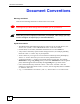
Document Conventions Icons Used in Figures Figures in this User’s Guide may use the following generic icons. The ZyXEL Device icon is not an exact representation of your device.
Safety Warnings Safety Warnings 1 For your safety, be sure to read and follow all warning notices and instructions. • Do NOT use this product near water, for example, in a wet basement or near a swimming pool. • Do NOT expose your device to dampness, dust or corrosive liquids. • Do NOT store things on the device. • Do NOT install, use, or service this device during a thunderstorm. There is a remote risk of electric shock from lightning. • Connect ONLY suitable accessories to the device.
Safety Warnings NBG410W3G Series User’s Guide 7
Safety Warnings 8 NBG410W3G Series User’s Guide
Contents Overview Contents Overview Introduction ............................................................................................................................ 33 Getting to Know Your ZyXEL Device ......................................................................................... 35 Introducing the Web Configurator .............................................................................................. 43 Wizard Setup ...............................................................
Contents Overview 10 NBG410W3G Series User’s Guide
Table of Contents Table of Contents About This User's Guide .......................................................................................................... 3 Document Conventions............................................................................................................ 4 Safety Warnings........................................................................................................................ 6 Contents Overview .......................................................
Table of Contents 2.4 Navigating the ZyXEL Device Web Configurator ................................................................. 46 2.4.1 Title Bar ...................................................................................................................... 46 2.4.2 Main Window .............................................................................................................. 47 2.4.3 HOME Screen ........................................................................................
Table of Contents 5.3.1 IP Pool Setup ........................................................................................................... 103 5.4 RIP Setup .......................................................................................................................... 103 5.5 Multicast ............................................................................................................................ 103 5.6 WINS .....................................................................
Table of Contents 8.2 Wireless Security Overview ............................................................................................... 148 8.2.1 SSID ......................................................................................................................... 148 8.2.2 MAC Address Filter .................................................................................................. 148 8.2.3 User Authentication ........................................................................
Table of Contents 10.1 Authentication Server Overview ...................................................................................... 191 10.2 Local User Database ..................................................................................................... 191 10.3 RADIUS ......................................................................................................................... 193 Chapter 11 Certificates .......................................................................
Table of Contents 12.3 NAT Overview Screen ..................................................................................................... 230 12.4 NAT Address Mapping ................................................................................................... 232 12.4.1 What NAT Does ..................................................................................................... 232 12.4.2 NAT Address Mapping Edit ...........................................................................
Table of Contents 15.1.2 System Timeout ..................................................................................................... 260 15.2 WWW (HTTP and HTTPS) ............................................................................................. 260 15.3 WWW .............................................................................................................................. 261 15.4 HTTPS Example ...................................................................................
Table of Contents 16.5.2 Web Configurator Easy Access ............................................................................. 288 Chapter 17 Custom Application .............................................................................................................. 291 17.1 Custom Application ......................................................................................................... 291 17.2 Custom Application Configuration ..........................................................
Table of Contents 20.1 Maintenance Overview .................................................................................................... 325 20.2 General Setup and System Name ................................................................................... 325 20.2.1 General Setup ....................................................................................................... 325 20.3 Configuring Password .....................................................................................
Table of Contents Appendix F Importing Certificates ........................................................................................ 403 Appendix G Legal Information.............................................................................................. 415 Appendix H Customer Support............................................................................................. 419 Index.............................................................................................................
List of Figures List of Figures Figure 1 3G WAN Application ................................................................................................................. 36 Figure 2 Secure Internet Access via Cable or DSL Modem ................................................................... 36 Figure 3 Front Panel ............................................................................................................................... 39 Figure 4 Login Screen ..................................
List of Figures Figure 39 Tutorial Example: DNS > System Edit-1 ............................................................................... 80 Figure 40 Tutorial Example: DNS > System Edit-2 ............................................................................... 81 Figure 41 Tutorial Example: DNS > System: Done ............................................................................... 81 Figure 42 Tutorial Example: Status .....................................................................
List of Figures Figure 82 DMZ Public Address Example .............................................................................................. 141 Figure 83 DMZ Private and Public Address Example .......................................................................... 142 Figure 84 NETWORK > DMZ > Port Roles ......................................................................................... 143 Figure 85 Example of a Wireless Network .............................................................
List of Figures Figure 125 SECURITY > CERTIFICATES > My Certificates > Import: PKCS#12 ............................... 204 Figure 126 SECURITY > CERTIFICATES > My Certificates > Create (Basic) .................................... 205 Figure 127 SECURITY > CERTIFICATES > My Certificates > Create (Advanced) ............................. 206 Figure 128 SECURITY > CERTIFICATES > Trusted CAs ...................................................................
List of Figures Figure 168 ADVANCED > REMOTE MGMT > SSH ............................................................................. 269 Figure 169 SSH Example 1: Store Host Key ........................................................................................ 270 Figure 170 SSH Example 2: Test ........................................................................................................ 270 Figure 171 SSH Example 2: Log in ...................................................................
List of Figures Figure 211 Masonry Plug and M4 Tap Screw ....................................................................................... 348 Figure 212 Pop-up Blocker ................................................................................................................... 353 Figure 213 Internet Options: Privacy .................................................................................................... 354 Figure 214 Internet Options: Privacy ......................................
List of Figures Figure 254 Security Certificate ............................................................................................................. 403 Figure 255 Login Screen ...................................................................................................................... 404 Figure 256 Certificate General Information before Import .................................................................... 404 Figure 257 Certificate Import Wizard 1 ..................................
List of Figures 28 NBG410W3G Series User’s Guide
List of Tables List of Tables Table 1 NBG410W3G Front Panel Lights .............................................................................................. 39 Table 2 NBG412W3G Front Panel Lights .............................................................................................. 40 Table 3 Title Bar: Web Configurator Icons ............................................................................................. 47 Table 4 Web Configurator HOME Screen ...................................
List of Tables Table 39 WIRELESS > Wi-Fi > MAC Filter .......................................................................................... 163 Table 40 Blocking All LAN to WAN IRC Traffic Example ..................................................................... 171 Table 41 Limited LAN to WAN IRC Traffic Example ............................................................................ 172 Table 42 SECURITY > FIREWALL > Default Rule ...............................................................
List of Tables Table 82 ADVANCED > REMOTE MGMT > DNS ............................................................................... 278 Table 83 ADVANCED > REMOTE MGMT > CNM ............................................................................... 279 Table 84 ADVANCED > UPnP ............................................................................................................. 282 Table 85 ADVANCED > UPnP > Ports .................................................................................
List of Tables Table 125 Alternative Subnet Mask Notation ....................................................................................... 379 Table 126 Subnet 1 .............................................................................................................................. 381 Table 127 Subnet 2 .............................................................................................................................. 382 Table 128 Subnet 3 ...........................................
P ART I Introduction Getting to Know Your ZyXEL Device (35) Introducing the Web Configurator (43) Wizard Setup (59) Tutorials (65) 33
CHAPTER 1 Getting to Know Your ZyXEL Device This chapter introduces the main features and applications of the ZyXEL Device. 1.1 Overview The ZyXEL Device is a high-security 3G router with wireless capability. Access the Internet with the 3G connection from any location with 3G coverage, with the option of using a wired WAN connection at the same time. Enhance network security by adding a De-Militarized Zone (DMZ) to your network.
Chapter 1 Getting to Know Your ZyXEL Device Figure 1 3G WAN Application 1.2.2 Secure Broadband Internet Access via Cable or DSL Modem For Internet access, connect the WAN Ethernet port to your existing Internet access gateway (company network, or your cable or DSL modem for example). Connect computers or servers to the LAN or DMZ ports for shared Internet access. The ZyXEL Device guarantees not only high speed Internet access, but secure internal network protection and traffic management as well.
Chapter 1 Getting to Know Your ZyXEL Device 1.4 Configuring Your ZyXEL Device’s Security Features Your ZyXEL Device comes with a variety of security features. This section summarizes these features and provides links to sections in the User’s Guide to configure security settings on your ZyXEL Device. Follow the suggestions below to improve security on your ZyXEL Device and network. 1.4.1 Control Access to Your Device Ensure only people with permission can access your ZyXEL Device.
Chapter 1 Getting to Know Your ZyXEL Device • Set the firewall to block ICMP requests. • Enable do not respond to requests for unauthorized services. • If you have a backup gateway (for example, backup Internet access) on your network, disable the Bypass Triangle Routes feature and enable IP Alias to put your backup gateway on a different subnet.
Chapter 1 Getting to Know Your ZyXEL Device 1.5.1 Front Panel Lights Figure 3 Front Panel The following tables describe the lights. Table 1 describes the light features in NBG410W3G, and Table 2 describes the light features in NBG412W3G. Table 1 NBG410W3G Front Panel Lights LED ICONS COLOR POWER Green Red LAN/DMZ 10/ 100 Green Orange WAN Green Orange Wi-Fi Green NBG410W3G Series User’s Guide STATUS DESCRIPTION Off The ZyXEL Device is turned off. On The ZyXEL Device is ready and running.
Chapter 1 Getting to Know Your ZyXEL Device Table 1 NBG410W3G Front Panel Lights (continued) LED ICONS 3G OPERATION COLOR STATUS DESCRIPTION Green On The ZyXEL Device has a successful 3G connection. Flashing The ZyXEL Device has detected an available 3G network, but has not yet connected to it. On The ZyXEL Device has a successful 3.5G connection Flashing The ZyXEL Device has detected an available 3.5G network, but has not yet connected to it. On The ZyXEL Device has a successful 2G or 2.
Chapter 1 Getting to Know Your ZyXEL Device Table 2 NBG412W3G Front Panel Lights (continued) LED Wi-Fi 3G MODE 3G LINK ICONS COLOR STATUS DESCRIPTION Green Off The wireless connection through the built-in Wi-Fi card is not ready, or has failed. On The wireless LAN through the built-in wireless LAN card is ready. Flashing The wireless LAN through the built-in wireless LAN card is sending or receiving packets. On The 3G function is activated. Off The 3G function is not activated.
Chapter 1 Getting to Know Your ZyXEL Device 42 NBG410W3G Series User’s Guide
CHAPTER 2 Introducing the Web Configurator This chapter describes how to access the ZyXEL Device web configurator and provides an overview of its screens. 2.1 Web Configurator Overview The web configurator is an HTML-based management interface that allows easy ZyXEL Device setup and management via Internet browser. Use Internet Explorer 6.0 and later or Netscape Navigator 7.0 and later versions. The recommended screen resolution is 1024 by 768 pixels.
Chapter 2 Introducing the Web Configurator Figure 4 Login Screen 5 You should see a screen asking you to change your password (highly recommended) as shown next. Type a new password (and retype it to confirm) and click Apply or click Ignore. Figure 5 Change Password Screen 6 Click Apply in the Replace Certificate screen to create a certificate using your ZyXEL Device’s MAC address that will be specific to this device.
Chapter 2 Introducing the Web Configurator " The management session automatically times out when the time period set in the Administrator Inactivity Timer field expires (default five minutes). Simply log back into the ZyXEL Device if this happens to you. 2.3 Resetting the ZyXEL Device If you forget your password or cannot access the web configurator, you will need to reload the factory-default configuration file or use the RESET button on the back of the ZyXEL Device.
Chapter 2 Introducing the Web Configurator Figure 7 Example Xmodem Upload Type the configuration file’s location, or click Browse to search for it. Choose the Xmodem protocol. Then click Send. 6 After successful firmware upload, enter "atgo" to restart the router. 2.4 Navigating the ZyXEL Device Web Configurator The following summarizes how to navigate the web configurator from the HOME screen.
Chapter 2 Introducing the Web Configurator The icons provide the following functions. Table 3 Title Bar: Web Configurator Icons ICON DESCRIPTION Wizard Click this icon to open one of the web configurator wizards. See Chapter 3 on page 59 for more information. Help Click this icon to open the help page for the current screen. 2.4.2 Main Window The main window shows the screen you select in the navigation panel. It is discussed in more detail in the rest of this document.
Chapter 2 Introducing the Web Configurator Table 4 Web Configurator HOME Screen (continued) LABEL DESCRIPTION System Information System Name This is the System Name you enter in the MAINTENANCE > General screen. It is for identification purposes. Click the field label to go to the screen where you can specify a name for this ZyXEL Device. Model This is the model name of your ZyXEL Device. Bootbase Version This is the bootbase version and the date created.
Chapter 2 Introducing the Web Configurator Table 4 Web Configurator HOME Screen (continued) LABEL DESCRIPTION Status For the LAN and DMZ ports, this displays the port speed and duplex setting. Ethernet port connections can be in half-duplex or full-duplex mode. Full-duplex refers to a device's ability to send and receive simultaneously, while half-duplex indicates that traffic can flow in only one direction at a time.
Chapter 2 Introducing the Web Configurator Table 4 Web Configurator HOME Screen (continued) LABEL DESCRIPTION Roaming Network This field is available only when you insert a 3G card that supports the roaming feature. This displays whether the card is able to connect to other ISPs’ base stations. Dormant State This field is available only when you insert a 3G card that supports the dormant state. This displays whether the card is in dormant state.
Chapter 2 Introducing the Web Configurator Table 4 Web Configurator HOME Screen (continued) LABEL DESCRIPTION New PIN Code Configure a PIN code for the SIM card. You can specify any four to eight digits to have a new PIN code or enter the previous PIN code. Confirm New PIN Code Enter the PIN code again for confirmation. Apply Click Apply to save your changes in this section.
Chapter 2 Introducing the Web Configurator Table 4 Web Configurator HOME Screen (continued) LABEL DESCRIPTION Latest Alerts This table displays the five most recent alerts recorded by the ZyXEL Device. You can see more information in the View Log screen, such as the source and destination IP addresses and port numbers of the incoming packets. Date/Time This is the date and time the alert was recorded. Message This is the reason for the alert.
Chapter 2 Introducing the Web Configurator Table 5 Screens Summary (continued) LINK TAB FUNCTION Wi-Fi Wireless Card Use this screen to configure the wireless LAN settings. Security Use this screen to configure the Wi-Fi security settings.
Chapter 2 Introducing the Web Configurator Table 5 Screens Summary (continued) LINK TAB FUNCTION REMOTE MGMT WWW Use this screen to configure through which interface(s) and from which IP address(es) users can use HTTPS or HTTP to manage the ZyXEL Device. SSH Use this screen to configure through which interface(s) and from which IP address(es) users can use Secure Shell to manage the ZyXEL Device.
Chapter 2 Introducing the Web Configurator Figure 10 HOME > Show Statistics The following table describes the labels in this screen. Table 6 HOME > Show Statistics LABEL DESCRIPTION Click the icon to display the chart of throughput statistics. Port These are the ZyXEL Device’s interfaces.
Chapter 2 Introducing the Web Configurator Figure 11 HOME > Show Statistics > Line Chart The following table describes the labels in this screen. Table 7 HOME > Show Statistics > Line Chart LABEL DESCRIPTION Click the icon to go back to the Show Statistics screen. Port Select the check box(es) to display the throughput statistics of the corresponding interface(s). B/s Specify the direction of the traffic for which you want to show throughput statistics in this table.
Chapter 2 Introducing the Web Configurator Figure 12 HOME > DHCP Table The following table describes the labels in this screen. Table 8 HOME > DHCP Table LABEL DESCRIPTION Interface Select LAN or DMZ to show the current DHCP client information for the specified interface. # This is the index number of the host computer. IP Address This field displays the IP address relative to the # field listed above. Host Name This field displays the computer host name.
Chapter 2 Introducing the Web Configurator 58 NBG410W3G Series User’s Guide
CHAPTER 3 Wizard Setup This chapter provides information on the Wizard Setup screens in the web configurator. 3.1 Wizard Setup Overview The web configurator's setup wizards help you configure Internet connection settings. In the HOME screen, click the wizard icon to open the Wizard Setup Welcome screen. The following summarizes the wizards you can select: • Internet Access Setup Click this link to open a wizard to set up an Internet connection for WAN 1 (the WAN port) on the ZyXEL Device.
Chapter 3 Wizard Setup The wizard screen varies according to the type of encapsulation that you select in the Encapsulation field. 3.2.1.1 Ethernet For ISPs (such as Telstra) that send UDP heartbeat packets to verify that the customer is still online, please create a WAN-to-WAN/ZyXEL Device firewall rule for those packets. Contact your ISP to find the correct port number. Choose Ethernet when the WAN port is used as a regular Ethernet port.
Chapter 3 Wizard Setup Table 9 ISP Parameters: Ethernet Encapsulation LABEL DESCRIPTION Gateway IP Address Enter the gateway IP address in this field. First DNS Server Second DNS Server Enter the DNS server's IP address(es) in the field(s) to the right. Leave the field as 0.0.0.0 if you do not want to configure DNS servers. If you do not configure a DNS server, you must know the IP address of a machine in order to access it. Back Click Back to return to the previous wizard screen.
Chapter 3 Wizard Setup Table 10 ISP Parameters: PPPoE Encapsulation (continued) LABEL DESCRIPTION User Name Type the user name given to you by your ISP. Password Type the password associated with the user name above. Retype to Confirm Type your password again for confirmation. Nailed-Up Select Nailed-Up if you do not want the connection to time out. Idle Timeout Type the time in seconds that elapses before the router automatically disconnects from the PPPoE server.
Chapter 3 Wizard Setup Figure 16 ISP Parameters: PPTP Encapsulation The following table describes the labels in this screen. Table 11 ISP Parameters: PPTP Encapsulation LABEL DESCRIPTION ISP Parameters for Internet Access Encapsulation Select PPTP from the drop-down list box. To configure a PPTP client, you must configure the User Name and Password fields for a PPP connection and the PPTP parameters for a PPTP connection. User Name Type the user name given to you by your ISP.
Chapter 3 Wizard Setup Table 11 ISP Parameters: PPTP Encapsulation LABEL DESCRIPTION Connection ID/ Name Enter the connection ID or connection name in this field. It must follow the "c:id" and "n:name" format. For example, C:12 or N:My ISP. This field is optional and depends on the requirements of your xDSL modem. WAN IP Address Assignment IP Address Assignment Select Dynamic If your ISP did not assign you a fixed IP address. This is the default selection.
CHAPTER 4 Tutorials This section describes how to do the following. 1 2 3 4 Set up a DMZ (De-Militarized Zone). Use an H.323 VoIP phone on your LAN. Use NAT (Network Address Translation) with multiple public IP addresses. Allow multiple game players to connect to the same server. 4.1 DMZ Overview The DMZ is a separate network for devices that provide services to users on the Internet.
Chapter 4 Tutorials 4.2 DMZ Setup Example In this example the DMZ uses private IP addresses and the default subnet mask of 255.255.255.0. (See Appendix C on page 377 for information on subnetting.) You can also use a static public IP address for your file server. Figure 19 DMZ Tutorial: DMZ Setup DMZ 192.168.2.0 File server 192.168.2.33 Internet LAN 192.168.1.0 Host 192.168.1.33 WAN1: 123.11.11.11 4.2.1 Basic Setup Follow these steps to set up your DMZ with a private or a public IP address. 4.2.1.
Chapter 4 Tutorials Figure 20 DMZ Tutorial: NETWORK > DMZ > Static DHCP 4.2.1.3 Public and Private IP Addresses 1 In Windows Networking (NetBIOS over TCP/IP) select Allow between DMZ and LAN. In this example, both the file server on the DMZ and a computer on the LAN use a Windows OS. Enable NetBIOS to allow LAN computers to use Windows programs such as Windows Explorer to access the server on the DMZ. 2 Click Apply.
Chapter 4 Tutorials Figure 22 DMZ Tutorial: ADVANCED > NAT Overview This completes basic setup of your DMZ. 4.2.2 Advanced Setup In this scenario the file server runs an FTP (File Transfer Protocol) download service. Since FTP is not compatible with NAT, you can use the ALG (Application Layer Gateway) to manage FTP. (See Chapter 18 on page 293 for more information.) To allow FTP sessions to be initiated by users on the WAN, port-forwarding is also required (see Section 12.
Chapter 4 Tutorials Port Forwarding Setup 1 To configure port forwarding, first configure a static IP on the file server if you haven’t already. See Section 4.2.1.2 on page 66. 2 Click ADVANCED > NAT > Port Forwarding to open the Port Forwarding screen. 3 In the WAN Interface field select the correct WAN for your network. This example uses WAN1. 4 In the rule row you are configuring select Active. 5 In the Name field type a descriptive name for the port forwarding rule. This example uses FTP.
Chapter 4 Tutorials You need to define two rules - one to drop all traffic from the WAN to the DMZ, the other to permit HTTP and FTP traffic from the WAN to the DMZ. This ensures that only HTTP and FTP traffic from the WAN to the DMZ is permitted and all other traffic is blocked. If you have not already done so, define a static IP address for the file server (see step 1 on page 69 for instructions). 1 Click SECURITY > Firewall > Rule Summary to display the Rule Summary screen.
Chapter 4 Tutorials Figure 26 DMZ Tutorial: NETWORK > Firewall > Rule Summary: Firewall - Edit 11 Repeat the firewall rule setup procedure to set up a rule for WAN1 to DMZ traffic with the same source and destination addresses. In the Edit Service section of the Firewall Edit screen select HTTP and FTP so that they appear in the Selected Service(s) field. 12 In the Action for Matched Packets field select Permit from the drop-down list and click Apply.
Chapter 4 Tutorials Figure 27 DMZ Tutorial: SECURITY > Firewall > Rule Summary Example This completes setup of a firewall rules for the file server on your DMZ. 4.4 Setting Up a VoIP Phone with H.323 You can use the ZyXEL Device to manage calls from your VoIP enabled phone using H.323. The following diagram shows an example of a VoIP phone configured to make calls over the Internet. Figure 28 Tutorial: H.323 Phone Setup Internet LAN: 192.168.1.33 WAN: 123.23.23.
Chapter 4 Tutorials Figure 29 H.323 Tutorial: NETWORK > LAN > Static DHCP 4 Click NETWORK > LAN to display the LAN screen. Ensure that Server is selected in the drop-down box in the DHCP field. Set up ALG Follow these steps to set up ALG (Application Layer Gateway) to let your ZyXEL Device manage H.323 traffic. (For more information on ALG see Chapter 18 on page 293.) 1 Click ADVANCED > ALG to display the ALG screen. Select Enable H.323 ALG and click Apply.
Chapter 4 Tutorials 6 Type the IP address of your VoIP phone in the Server IP Address field. In this example 192.168.1.33 is used. 7 Click Apply. Figure 31 H.323 Tutorial: ADVANCED > NAT > Port Forwarding Set up a Firewall Rule 1 Click SECURITY > Firewall > Rule Summary to display the Rule Summary screen and to configure firewall rules on traffic between the VoIP phone and the WAN. In this example, traffic between the file server and WAN1 is restricted to H.323 traffic. 2 The Rule Summary screen appears.
Chapter 4 Tutorials field - 123.23.23.23 and click Add so that the IP address appears in the Destination Address(es) field. If you are using a H.323 server, use its IP address instead. 5 In the Edit Destination Address section select Single Address in the drop-down box in the Address Type field. Type the destination address of H.323 traffic in the Start IP Address field - 192.168.1.33 and click Add so that the IP address appears in the Source Address(es) field. 6 In the Edit Service section select H.
Chapter 4 Tutorials Figure 33 H.323 Tutorial: SECURITY > Firewall > Rule Summary 8 Repeat the firewall rule setup procedure to add a similar firewall rule for H.323 traffic from the WAN to the LAN, using the same WAN IP address and LAN IP address settings. 9 In the Rule Summary screen select Any and Any from the drop-down list in the Packet Direction fields and click Refresh to check your firewall rule settings.
Chapter 4 Tutorials Figure 34 H.323 Tutorial: SECURITY > Firewall > Rule Summary That completes setup of your H.323 VoIP phone. 4.5 Using NAT with Multiple Public IP Addresses This section shows you examples of how to set up your ZyXEL Device if you have more than one fixed (static) IP address from your ISP. 4.5.1 Example Parameters and Scenario The following table shows the public IP addresses from your ISP and your ZyXEL Device’s LAN IP address. Public IP Addresses 1.2.3.4 to 1.2.3.
Chapter 4 Tutorials Figure 35 Tutorial Example: Using NAT with Static Public IP Addresses LAN WAN Mapping rules: 192.168.1.12 <---> 1.2.3.5 (1-1) 192.168.1.13 <---> 1.2.3.6 (1-1) Other outgoing LAN traffic ---> 1.2.3.4 (M-1) Incoming traffic <--- 1.2.3.4 (Server) FTP 192.168.1.39 FTP 192.168.1.39 192.168.1.1 Web 192.168.1.12 1.2.3.4 1.2.3.5 1.2.3.6 1.2.3.7 Mail 192.168.1.13 To set up this network, we are going to: 1 Configure the WAN 1 connection to use the first public IP address (1.2.3.4).
Chapter 4 Tutorials Figure 36 Tutorial Example: WAN Connection with a Static Public IP Address LAN WAN 192.168.1.1 1.2.3.4 1 Click NETWORK > WAN > WAN 1. 2 Select PPPoE (PPP over Ethernet) from the Encapsulation drop-down list box. 3 In the ISP Parameters for Internet Access section, enter the information (such as the user name and password) provided by your ISP. If your ISP didn’t give you the service name, leave the field blank.
Chapter 4 Tutorials 7 The System screen displays. Click the Insert button to configure the IP address of the DNS server the ZyXEL Device can query to resolve domain names. Figure 38 Tutorial Example: DNS > System 8 Select Public DNS Server and enter the first DNS server’s IP address given by your ISP. Click Apply.
Chapter 4 Tutorials Figure 40 Tutorial Example: DNS > System Edit-2 10 The DNS > System screen should look as shown. Figure 41 Tutorial Example: DNS > System: Done 11 Go to the Home screen to check your WAN connection status. Make sure the status is not down.
Chapter 4 Tutorials Figure 42 Tutorial Example: Status 4.5.3 Public IP Address Mapping To have the local computers and servers use specific WAN IP addresses, you need to map static public IP addresses to them. " " The one-to-one NAT address mapping rules are for both incoming and outgoing connections. The ZyXEL Device forwards traffic that is initiated from either the LAN or the WAN to the destination IP address.
Chapter 4 Tutorials Figure 43 Tutorial Example: Mapping Multiple Public IP Addresses to Inside Servers LAN 192.168.1.39 1.2.3.4 1.2.3.5 1.2.3.6 1.2.3.7 192.168.1.39 Web 192.168.1.12 " WAN Mapping rules: 192.168.1.12 <---> 1.2.3.5 (1-1) 192.168.1.13 <---> 1.2.3.6 (1-1) Other outgoing LAN traffic ---> 1.2.3.4 (M-1) Mail 192.168.1.13 The ZyXEL Device applies the rules in the order that you specify. You should put any one-to-one rules before a many-to-one rule. 1 Click ADVANCED > NAT.
Chapter 4 Tutorials Figure 44 Tutorial Example: NAT > NAT Overview 3 Click the Address Mapping tab. 4 Select WAN 1. 5 Click the first rule’s Edit icon ( ) in the Modify column to display the Address Mapping Rule screen.
Chapter 4 Tutorials Figure 45 Tutorial Example: NAT > Address Mapping 6 Map a public IP address to the web server. Select the One-to-One type and enter 192.168.1.12 as the local start IP address and 1.2.3.5 as the global start IP address. Click Apply. Figure 46 Tutorial Example: NAT Address Mapping Edit: One-to-One (1) 7 Click the second rule’s Edit icon ( ). 8 Map a public IP address to the mail server. Select the One-to-One type and enter 192.168.1.13 as the local start IP address and 1.2.3.
Chapter 4 Tutorials Figure 47 Tutorial Example: NAT Address Mapping Edit: One-to-One (2) 9 Click the third rule’s Edit icon ( ). 10 Map a public IP address to other outgoing LAN traffic. Select the Many-to-One type and enter 192.168.1.1 as the local start IP address, 192.168.1.254 as the local end IP address and 1.2.3.4 as the global start IP address. Click Apply. Figure 48 Tutorial Example: NAT Address Mapping Edit: Many-to-One 11 After the configurations, the Address Mapping screen looks as shown.
Chapter 4 Tutorials Figure 49 Tutorial Example: NAT Address Mapping Done " To allow traffic from the WAN to be forwarded through the ZyXEL Device, you must also create a firewall rule. Refer to Section 4.5.5 on page 89 for more information. 4.5.4 Forwarding Traffic from the WAN to a Local Computer A server NAT address mapping rule allows computers behind the NAT be accessible to the outside world.
Chapter 4 Tutorials Figure 50 Tutorial Example: Forwarding Incoming FTP Traffic to a Local Computer LAN FTP 192.168.1.39 WAN Mapping rules: Incoming traffic <--- 1.2.3.4 (Server) FTP 1.2.3.4 1.2.3.5 1.2.3.6 1.2.3.7 192.168.1.39 Web 192.168.1.12 Mail 192.168.1.13 1 Click ADVANCED > NAT > Address Mapping. 2 Click the forth rule’s Edit icon ( ) to configure a server rule. Figure 51 Tutorial Example: NAT Address Mapping Edit: Server 3 Click the Port Forwarding tab. 4 Select WAN 1.
Chapter 4 Tutorials Figure 52 Tutorial Example: NAT Port Forwarding 4.5.5 Allow WAN-to-LAN Traffic through the Firewall By default, the ZyXEL Device blocks any traffic initiated from the WAN to the LAN. To have the ZyXEL Device forward traffic initiated from WAN 1 to a local computer or server on the LAN, you need to configure a firewall rule to allow it.
Chapter 4 Tutorials 1 Click SECURITY > FIREWALL. 2 Make sure the firewall is enabled and traffic from WAN 1 to the LAN is dropped. Figure 54 Tutorial Example: Firewall Default Rule 3 Go to the Rule Summary screen. 4 Select WAN1 to LAN as the packet direction and click Refresh. 5 Click the insert icon to create a new firewall rule.
Chapter 4 Tutorials 6 Configure a firewall rule to allow HTTP traffic from the WAN to the web server. Enter a descriptive name (W-L_Web for example). Select Any in the Destination Address(es) box and click Delete. Select Single Address as the destination address type. Enter 192.168.1.12 and click Add.
Chapter 4 Tutorials Figure 57 Tutorial Example: Firewall Rule: WAN to LAN Service Edit for Web Server 8 Click the insert icon to configure a firewall rule to allow traffic from the WAN to the mail server. Enter a descriptive name (W-L_Mail for example). Select Any in the Destination Address(es) box and click Delete. Select Single Address as the destination address type. Enter 192.168.1.13 and click Add.
Chapter 4 Tutorials Figure 58 Tutorial Example: Firewall Rule: WAN to LAN Address Edit for Mail Server 9 Select Any(All) in the Available Services box on the left, and click >> to add it to the Selected Service(s) box on the right. Click Apply.
Chapter 4 Tutorials 10 Click the insert icon to configure a firewall rule to allow FTP traffic from the WAN to the FTP server. Enter a descriptive name (W-L_FTP for example). Select Any in the Destination Address(es) box and click Delete. Select Single Address as the destination address type. Enter 192.168.1.39 and click Add.
Chapter 4 Tutorials Figure 61 Tutorial Example: Firewall Rule: WAN to LAN Service Edit for FTP Server 12 When you are done, the Rule Summary screen looks as shown.
Chapter 4 Tutorials 4.5.6 Testing the Connections 1 Open the web browser on one of the local computers and enter any web site’s URL in the address bar. If you can access the web site, your WAN 1 connection and NAT address mapping are configured successfully. If you cannot access it, make sure you entered the correct information in the WAN and NAT Address Mapping screens. Also check that the Internet account is active and the computer’s IP address is in the same subnet as the ZyXEL Device.
Chapter 4 Tutorials Figure 63 Tutorial Example: NAT Address Mapping Done: Game Playing " To allow traffic from the WAN to be forwarded through the ZyXEL Device, you must also create a firewall rule. Refer to Section 4.5.5 on page 89 for more information.
Chapter 4 Tutorials 98 NBG410W3G Series User’s Guide
P ART II Network LAN Screens (101) WAN Screens (111) DMZ Screens (135) 99
CHAPTER 5 LAN Screens This chapter describes how to configure LAN settings. 5.1 LAN, WAN and the ZyXEL Device A network is a shared communication system to which many computers are attached. The Local Area Network (LAN) includes the computers and networking devices in your home or office that you connect to the ZyXEL Device’s LAN ports. The Wide Area Network (WAN) is another network (most likely the Internet) that you connect to the ZyXEL Device’s WAN port.
Chapter 5 LAN Screens feature of the ZyXEL Device. The Internet Assigned Number Authority (IANA) reserved this block of addresses specifically for private use; please do not use any other number unless you are told otherwise. If you select 192.168.1.0 as the network number; it covers 254 individual addresses, from 192.168.1.1 to 192.168.1.254 (zero and 255 are reserved).
Chapter 5 LAN Screens 5.3.1 IP Pool Setup The ZyXEL Device is pre-configured with a pool of IP addresses for the computers on your LAN. See Chapter 22 on page 345 for the default IP pool range. Do not assign your LAN computers static IP addresses that are in the DHCP pool. 5.4 RIP Setup RIP (Routing Information Protocol, RFC 1058 and RFC 1389) allows a router to exchange routing information with other routers. RIP Direction controls the sending and receiving of RIP packets.
Chapter 5 LAN Screens The ZyXEL Device supports both IGMP version 1 (IGMP-v1) and IGMP version 2 (IGMPv2). At start up, the ZyXEL Device queries all directly connected networks to gather group membership. After that, the ZyXEL Device periodically updates this information. IP multicasting can be enabled/disabled on the ZyXEL Device LAN and/or WAN interfaces in the web configurator (LAN; WAN). Select None to disable IP multicasting on these interfaces. 5.
Chapter 5 LAN Screens The following table describes the labels in this screen. Table 12 NETWORK > LAN LABEL DESCRIPTION LAN TCP/IP IP Address Type the IP address of your ZyXEL Device in dotted decimal notation. 192.168.1.1 is the factory default. Alternatively, click the right mouse button to copy and/or paste the IP address. IP Subnet Mask The subnet mask specifies the network number portion of an IP address.
Chapter 5 LAN Screens Table 12 NETWORK > LAN (continued) LABEL DESCRIPTION DHCP WINS Server 1, 2 Type the IP address of the WINS (Windows Internet Naming Service) server that you want to send to the DHCP clients. The WINS server keeps a mapping table of the computer names on your network and the IP addresses that they are currently using.
Chapter 5 LAN Screens Figure 66 NETWORK > LAN > Static DHCP The following table describes the labels in this screen. Table 13 NETWORK > LAN > Static DHCP LABEL DESCRIPTION # This is the index number of the Static IP table entry (row). MAC Address Type the MAC address of a computer on your LAN. IP Address Type the IP address that you want to assign to the computer on your LAN. Alternatively, click the right mouse button to copy and/or paste the IP address. Apply Click Apply to save your changes.
Chapter 5 LAN Screens The ZyXEL Device supports three logical LAN interfaces via its single physical LAN Ethernet interface. The ZyXEL Device itself is the gateway for each of the logical LAN networks. When you use IP alias, you can also configure firewall rules to control access between the LAN's logical networks (subnets). " Make sure that the subnets of the logical networks do not overlap. The following figure shows a LAN divided into subnets A, B, and C.
Chapter 5 LAN Screens The following table describes the labels in this screen. Table 14 NETWORK > LAN > IP Alias LABEL DESCRIPTION Enable IP Alias 1, 2 Select the check box to configure another LAN network for the ZyXEL Device. IP Address Enter the IP address of your ZyXEL Device in dotted decimal notation. Alternatively, click the right mouse button to copy and/or paste the IP address.
Chapter 5 LAN Screens " Your changes are also reflected in the DMZ Port Roles screen. Figure 69 NETWORK > LAN > Port Roles The following table describes the labels in this screen. Table 15 NETWORK > LAN > Port Roles LABEL DESCRIPTION LAN Select a port’s LAN radio button to use the port as part of the LAN. The port will use the ZyXEL Device’s LAN IP address and MAC address. DMZ Select a port’s DMZ radio button to use the port as part of the DMZ.
CHAPTER 6 WAN Screens This chapter describes how to configure WAN settings. " WAN 2 refers to the 3G card on the supported ZyXEL Device. 6.1 WAN Overview • Use the WAN General screen to configure operation mode, route priority and connection test for the ZyXEL Device. • Use the WAN 1 screen to configure the WAN1 interface for Internet access on the ZyXEL Device. • Use the 3G (WAN 2) screen to configure the WAN2 interface for Internet access on the ZyXEL Device.
Chapter 6 WAN Screens 6.3 TCP/IP Priority (Metric) The metric represents the "cost of transmission". A router determines the best route for transmission by choosing a path with the lowest "cost". RIP routing uses hop count as the measurement of cost, with a minimum of "1" for directly connected networks. The number must be between "1" and "15"; a number greater than "15" means the link is down. The smaller the number, the lower the "cost".
Chapter 6 WAN Screens Figure 71 NETWORK > WAN General NBG410W3G Series User’s Guide 113
Chapter 6 WAN Screens The following table describes the labels in this screen. Table 16 NETWORK > WAN General LABEL DESCRIPTION Active/Passive (Fail Over) Mode The ZyXEL Device uses the second highest priority WAN interface as a back up. This means that the ZyXEL Device will normally use the highest priority (primary) WAN interface (depending on the priorities you configure in the Route Priority fields).
Chapter 6 WAN Screens Table 16 NETWORK > WAN General (continued) LABEL DESCRIPTION Check Traffic Redirection Connectivity Select the check box to have the ZyXEL Device periodically test the traffic redirect connection. Select Ping Default Gateway to have the ZyXEL Device ping the backup gateway's IP address. Select Ping this Address and enter a domain name or IP address of a reliable nearby computer (for example, your ISP's DNS server address) to have the ZyXEL Device ping that address.
Chapter 6 WAN Screens You can obtain your IP address from the IANA, from an ISP or have it assigned by a private network. If you belong to a small organization and your Internet access is through an ISP, the ISP can provide you with the Internet addresses for your local networks. On the other hand, if you are part of a much larger organization, you should consult your network administrator for the appropriate IP addresses.
Chapter 6 WAN Screens 6.8 WAN 1 Use this screen to change your ZyXEL Device's WAN 1 ISP, IP and MAC settings. Click NETWORK > WAN > WAN 1 to display this screen. The screen differs by the encapsulation. " The WAN 1 and WAN 2 IP addresses of a ZyXEL Device with multiple WAN interfaces must be on different subnets. 6.8.
Chapter 6 WAN Screens The following table describes the labels in this screen. Table 18 NETWORK > WAN > WAN 1 (Ethernet Encapsulation) LABEL DESCRIPTION ISP Parameters for Internet Access Encapsulation You must choose the Ethernet option when the WAN port is used as a regular Ethernet. Service Type Choose from Standard, Telstra (RoadRunner Telstra authentication method), RRManager (Roadrunner Manager authentication method), RR-Toshiba (Roadrunner Toshiba authentication method) or Telia Login.
Chapter 6 WAN Screens Table 18 NETWORK > WAN > WAN 1 (Ethernet Encapsulation) (continued) LABEL DESCRIPTION RIP Direction RIP (Routing Information Protocol) allows a router to exchange routing information with other routers. The RIP Direction field controls the sending and receiving of RIP packets. Choose Both, None, In Only or Out Only. When set to Both or Out Only, the ZyXEL Device will broadcast its routing table periodically.
Chapter 6 WAN Screens 6.8.2 PPPoE Encapsulation The ZyXEL Device supports PPPoE (Point-to-Point Protocol over Ethernet). PPPoE is an IETF standard (RFC 2516) specifying how a personal computer (PC) interacts with a broadband modem (DSL, cable, wireless, etc.) connection. The PPPoE option is for a dial-up connection using PPPoE. For the service provider, PPPoE offers an access and authentication method that works with existing access control systems (for example RADIUS).
Chapter 6 WAN Screens Figure 73 NETWORK > WAN > WAN 1 (PPPoE Encapsulation) The following table describes the labels in this screen. Table 19 NETWORK > WAN > WAN 1 (PPPoE Encapsulation) LABEL DESCRIPTION ISP Parameters for Internet Access Encapsulation Select PPPoE for a dial-up connection using PPPoE. Service Name Type the PPPoE service name provided to you by your ISP. PPPoE uses a service name to identify and reach the PPPoE server. User Name Type the user name given to you by your ISP.
Chapter 6 WAN Screens Table 19 NETWORK > WAN > WAN 1 (PPPoE Encapsulation) (continued) LABEL DESCRIPTION Authentication Type The ZyXEL Device supports PAP (Password Authentication Protocol) and CHAP (Challenge Handshake Authentication Protocol). CHAP is more secure than PAP; however, PAP is readily available on more platforms. Use the drop-down list box to select an authentication protocol for outgoing calls.
Chapter 6 WAN Screens Table 19 NETWORK > WAN > WAN 1 (PPPoE Encapsulation) (continued) LABEL DESCRIPTION Enable Multicast Select this check box to turn on IGMP (Internet Group Multicast Protocol). IGMP is a network-layer protocol used to establish membership in a Multicast group - it is not used to carry user data. Multicast Version Choose None (default), IGMP-V1 or IGMP-V2.
Chapter 6 WAN Screens Figure 74 NETWORK > WAN > WAN 1 (PPTP Encapsulation) The following table describes the labels in this screen. Table 20 NETWORK > WAN > WAN 1 (PPTP Encapsulation) LABEL DESCRIPTION ISP Parameters for Internet Access 124 Encapsulation Set the encapsulation method to PPTP. The ZyXEL Device supports only one PPTP server connection at any given time.
Chapter 6 WAN Screens Table 20 NETWORK > WAN > WAN 1 (PPTP Encapsulation) (continued) LABEL DESCRIPTION Authentication Type The ZyXEL Device supports PAP (Password Authentication Protocol) and CHAP (Challenge Handshake Authentication Protocol). CHAP is more secure than PAP; however, PAP is readily available on more platforms. Use the drop-down list box to select an authentication protocol for outgoing calls.
Chapter 6 WAN Screens Table 20 NETWORK > WAN > WAN 1 (PPTP Encapsulation) (continued) LABEL DESCRIPTION RIP Version The RIP Version field controls the format and the broadcasting method of the RIP packets that the ZyXEL Device sends (it recognizes both formats when receiving). Choose RIP-1, RIP-2B or RIP-2M. RIP-1 is universally supported; but RIP-2 carries more information. RIP-1 is probably adequate for most networks, unless you have an unusual network topology.
Chapter 6 WAN Screens " " The actual data rate you obtain varies depending on your 3G card, the signal strength of the service provider’s base station, your service plan, etc. For NBG410W3G, you can use either the built-in 3G module or an external USB dongle to establish a 3G connection. Both connections cannot work simultaneously. If the signal strength of a 3G network is too low, the 3G card may switch to an available 2.5G or 2.75G network. See the following table for a comparison between 2G, 2.5G, 2.
Chapter 6 WAN Screens To change your ZyXEL Device's 3G WAN settings, click NETWORK > WAN > 3G (WAN 2) or WIRELESS > 3G (WAN 2). " 128 The WAN 1 and WAN 2 IP addresses of a ZyXEL Device with multiple WAN interfaces must be on different subnets.
Chapter 6 WAN Screens Figure 75 NETWORK > WAN > 3G (WAN 2) NBG410W3G Series User’s Guide 129
Chapter 6 WAN Screens The following table describes the labels in this screen. Table 22 NETWORK > WAN > 3G (WAN 2) LABEL DESCRIPTION WAN2 Setup Enable Select this option to enable WAN 2. The Network Type and Network Selection fields appear. 3G Card Configuration 3G Interface This displays the model of the 3G card installed in your ZyXEL Device. This may be installed internally or on the device’s USB port. Network Type Select the type of 3G service and frequency band for your 3G connection.
Chapter 6 WAN Screens Table 22 NETWORK > WAN > 3G (WAN 2) (continued) LABEL DESCRIPTION Authentication Type The ZyXEL Device supports PAP (Password Authentication Protocol) and CHAP (Challenge Handshake Authentication Protocol). CHAP is more secure than PAP; however, PAP is readily available on more platforms. Use the drop-down list box to select an authentication protocol for outgoing calls. Options are: CHAP/PAP - Your ZyXEL Device accepts either CHAP or PAP when requested by the ISP.
Chapter 6 WAN Screens Table 22 NETWORK > WAN > 3G (WAN 2) (continued) 132 LABEL DESCRIPTION Enable Multicast Select this check box to turn on IGMP (Internet Group Multicast Protocol). IGMP is a network-layer protocol used to establish membership in a Multicast group - it is not used to carry user data. Multicast Version Choose None (default), IGMP-V1 or IGMP-V2.
Chapter 6 WAN Screens Table 22 NETWORK > WAN > 3G (WAN 2) (continued) LABEL DESCRIPTION Actions when over % of time budget or % of data budget Specify the actions the ZyXEL Device takes when the specified percentage of time budget or data limit is exceeded. Enter a number from 1 to 99 in the percentage fields. If you change the value after you configure and enable budget control, the ZyXEL Device resets the statistics. Select Log to create a log. Select Alert to create an alert.
Chapter 6 WAN Screens Subnet 1 192.168.1.0 - 192.168.1.24 WAN Internet LAN Backup Gateway Subnet 2 192.168.2.0 - 192.168.2.24 6.11 Configuring Traffic Redirect To change your ZyXEL Device’s traffic redirect settings, click NETWORK > WAN > Traffic Redirect. The screen appears as shown. Figure 78 NETWORK > WAN > Traffic Redirect The following table describes the labels in this screen.
CHAPTER 7 DMZ Screens This chapter describes how to configure the ZyXEL Device’s DMZ. 7.1 DMZ The DeMilitarized Zone (DMZ) provides a way for public servers (Web, e-mail, FTP, etc.) to be visible to the outside world (while still being protected from DoS (Denial of Service) attacks such as SYN flooding and Ping of Death). These public servers can also still be accessed from the secure LAN.
Chapter 7 DMZ Screens Figure 79 NETWORK > DMZ The following table describes the labels in this screen. Table 24 NETWORK > DMZ LABEL DESCRIPTION DMZ TCP/IP IP Address Type the IP address of your ZyXEL Device’s DMZ port in dotted decimal notation. Note: Make sure the IP addresses of the LAN, WAN and DMZ are on separate subnets. 136 IP Subnet Mask The subnet mask specifies the network number portion of an IP address.
Chapter 7 DMZ Screens Table 24 NETWORK > DMZ (continued) LABEL DESCRIPTION Multicast Select IGMP V-1 or IGMP V-2 or None. IGMP (Internet Group Multicast Protocol) is a network-layer protocol used to establish membership in a Multicast group - it is not used to carry user data. IGMP version 2 (RFC 2236) is an improvement over version 1 (RFC 1112) but IGMP version 1 is still in wide use.
Chapter 7 DMZ Screens 7.3 DMZ Static DHCP This table allows you to assign IP addresses on the DMZ to specific individual computers based on their MAC Addresses. Every Ethernet device has a unique MAC (Media Access Control) address. The MAC address is assigned at the factory and consists of six pairs of hexadecimal characters, for example, 00:A0:C5:00:00:02. To change your ZyXEL Device’s static DHCP settings on the DMZ, click NETWORK > DMZ > Static DHCP. The screen appears as shown.
Chapter 7 DMZ Screens Table 25 NETWORK > DMZ > Static DHCP LABEL DESCRIPTION Apply Click Apply to save your changes. Reset Click Reset to begin configuring this screen afresh. 7.4 DMZ IP Alias IP alias allows you to partition a physical network into different logical networks over the same Ethernet interface. The ZyXEL Device has a single DMZ interface.
Chapter 7 DMZ Screens Figure 81 NETWORK > DMZ > IP Alias The following table describes the labels in this screen. Table 26 NETWORK > DMZ > IP Alias LABEL DESCRIPTION Enable IP Alias 1, 2 Select the check box to configure another DMZ network for the ZyXEL Device. IP Address Enter the IP address of your ZyXEL Device in dotted decimal notation. Note: Make sure the IP addresses of the LAN, WAN and DMZ are on separate subnets.
Chapter 7 DMZ Screens 7.5 DMZ Public IP Address Example The following figure shows a simple network setup with public IP addresses on the WAN and DMZ and private IP addresses on the LAN. Lower case letters represent public IP addresses (like a.b.c.d for example). The LAN port and connected computers (A through C) use private IP addresses that are in one subnet. The DMZ port and connected servers (D through F) use public IP addresses that are in another subnet.
Chapter 7 DMZ Screens Figure 83 DMZ Private and Public Address Example LAN A IP: 192.168.1.3 LAN IP: 192.168.1.1 B IP: 192.168.1.4 WAN IP: a.b.d.b DMZ IP: a.b.c.h IP: 10.0.0.1 C IP: 192.168.1.5 DMZ F IP: 10.0.0.2 D IP: a.b.c.i E IP: a.b.c.j 7.7 DMZ Port Roles Use the Port Roles screen to set ports as part of the LAN and/or DMZ interface. Ports 1~4 on the ZyXEL Device can be part of the LAN and/or DMZ interface.
Chapter 7 DMZ Screens Figure 84 NETWORK > DMZ > Port Roles The following table describes the labels in this screen. Table 27 NETWORK > DMZ > Port Roles LABEL DESCRIPTION LAN Select a port’s LAN radio button to use the port as part of the LAN. The port will use the ZyXEL Device’s LAN IP address and MAC address. DMZ Select a port’s DMZ radio button to use the port as part of the DMZ. The port will use the ZyXEL Device’s DMZ IP address and MAC address. Apply Click Apply to save your changes.
Chapter 7 DMZ Screens 144 NBG410W3G Series User’s Guide
P ART III Wireless Wi-Fi (147) 145
CHAPTER 8 Wi-Fi This chapter discusses how to configure wireless LAN on the ZyXEL Device. 8.1 Wi-Fi Introduction Your ZyXEL Device comes with an internal Wi-Fi card, providing AP (access point) functionality, and allowing you to set up a wireless LAN (WLAN). Before you set up your WLAN it is important to understand WLAN and WLAN security concepts.
Chapter 8 Wi-Fi Every wireless network must follow these basic guidelines. • Every wireless client in the same wireless network must use the same SSID. The SSID is the name of the wireless network. It stands for Service Set IDentity. • If two wireless networks overlap, they should use different channels. Like radio stations or television channels, each wireless network uses a specific channel, or frequency, to send and receive information.
Chapter 8 Wi-Fi You can use the MAC address filter to tell the AP which wireless clients are allowed or not allowed to use the wireless network. If a wireless client is allowed to use the wireless network, it still has to have the correct settings (SSID, channel, and security). If a wireless client is not allowed to use the wireless network, it does not matter if it has the correct settings. This type of security does not protect the information that is sent in the wireless network.
Chapter 8 Wi-Fi The types of encryption you can choose depend on the type of user authentication. (See Section 8.2.3 on page 149 for information about this.) Table 28 Types of Encryption for Each Type of Authentication No Authentication Weakest RADIUS Server No Security Static WEP 802.1x +Static WEP Strongest WPA-PSK WPA WPA2-PSK or WPA2-PSK-Mix WPA2 or WPA2-Mix For example, if the wireless network has a RADIUS server, you can choose WPA or WPA2.
Chapter 8 Wi-Fi 8.2.5 Additional Installation Requirements for Using 802.1x • A computer with an IEEE 802.11b/g wireless LAN card. • A computer equipped with a web browser (with JavaScript enabled) and/or Telnet. • A wireless station must be running IEEE 802.1x-compliant software. Currently, this is offered in Windows XP. • An optional network RADIUS server for remote user authentication and accounting. 8.
Chapter 8 Wi-Fi The following table describes the labels in this screen. Table 29 WIRELESS > Wi-Fi > Wireless Card LABEL DESCRIPTION Enable Wireless Card The wireless LAN through a wireless LAN card is turned off by default. Before you enable the wireless LAN you should configure security by setting MAC filters and/or 802.1x security; otherwise your wireless LAN will be vulnerable upon enabling it. Select the check box to enable the wireless LAN.
Chapter 8 Wi-Fi Table 29 WIRELESS > Wi-Fi > Wireless Card (continued) LABEL DESCRIPTION Select SSID Profile An SSID profile is the set of parameters relating to one of the ZyXEL Device’s BSSs. The SSID (Service Set IDentifier) identifies the Service Set with which a wireless client is associated. Wireless clients associating with the access point (AP) must have the same SSID.
Chapter 8 Wi-Fi Figure 87 WIRELESS > Wi-Fi > Configuring SSID The following table describes the labels in this screen. Table 30 WIRELESS > Wi-Fi > Configuring SSID LABEL DESCRIPTION Name Enter a name (up to 32 printable 7-bit ASCII characters) identifying this profile. SSID When a wireless client scans for an AP to associate with, this is the name that is broadcast and seen in the wireless client utility. Enter a descriptive name (up to 32 printable 7-bit ASCII characters) for the wireless LAN.
Chapter 8 Wi-Fi The following table describes the security modes you can configure. Table 31 Security Modes SECURITY MODE DESCRIPTION None Select this to have no data encryption. WEP Select this to use WEP encryption. 802.1x-Only Select this to use 802.1x authentication with no data encryption. 802.1x-Static64 Select this to use 802.1x authentication with a static 64bit WEP key and an authentication server. 802.1x-Static128 Select this to use 802.
Chapter 8 Wi-Fi 8.4.1 No Security " If you do not enable any wireless security on your ZyXEL Device, your network is accessible to any wireless networking device within range. Figure 89 WIRELESS > Wi-Fi > Security: None The following table describes the wireless LAN security labels in this screen. Table 33 WIRELESS > Wi-Fi > Security: None LABEL DESCRIPTION Name Type a name (up to 32 printable 7-bit ASCII characters) to identify this security profile.
Chapter 8 Wi-Fi Figure 90 WIRELESS > Wi-Fi > Security: WEP The following table describes the labels in this screen. Table 34 WIRELESS > Wi-Fi > Security: WEP LABEL DESCRIPTION Name Type a name to identify this security profile. Security Mode Select WEP from the drop-down list. WEP Encryption WEP (Wired Equivalent Privacy) provides data encryption to prevent unauthorized wireless stations from accessing data transmitted over the wireless network.
Chapter 8 Wi-Fi Figure 91 WIRELESS > Wi-Fi > Security: 802.1x Only The following table describes the labels in this screen. Table 35 WIRELESS > Wi-Fi > Security: 802.1x Only LABEL DESCRIPTION Name Type a name to identify this security profile. Security Mode Select 8021X-Only from the drop-down list. ReAuthentication Timer Specify how often wireless clients have to resend user names and passwords in order to stay connected. Enter a time interval between 600 and 65535 seconds.
Chapter 8 Wi-Fi Figure 92 WIRELESS > Wi-Fi > Security: 802.1x + Static WEP The following table describes the labels in this screen. Table 36 WIRELESS > Wi-Fi > Security: 802.1x + Static WEP LABEL DESCRIPTION Name Type a name to identify this security profile. Security Mode Select 8021X-Static64 or 8021X-Static128 from the drop-down list.
Chapter 8 Wi-Fi Table 36 WIRELESS > Wi-Fi > Security: 802.1x + Static WEP (continued) LABEL DESCRIPTION Apply Click Apply to save your customized settings and exit this screen. Cancel Click Cancel to exit this screen without saving. 8.4.5 WPA, WPA2, WPA2-MIX Click WIRELESS > Wi-Fi > Security > Edit. Select WPA, WPA2 or WPA2-MIX from the Security Mode list. Figure 93 WIRELESS > Wi-Fi > Security: WPA, WPA2 or WPA2-MIX The following table describes the labels in this screen.
Chapter 8 Wi-Fi Table 37 WIRELESS > Wi-Fi > Security: WPA, WPA2 or WPA2-MIX (continued) LABEL DESCRIPTION PMK Cache This field is available only when you select WPA2 or WPA2-MIX. When a wireless client moves from one AP’s coverage area to another, it performs an authentication procedure (exchanging security information) with the new AP.
Chapter 8 Wi-Fi Table 38 WIRELESS > Wi-Fi > Security: WPA(2)-PSK (continued) LABEL DESCRIPTION Idle Timeout The ZyXEL Device automatically disconnects a wireless client from the wireless network after a period of inactivity. The wireless client needs to send the username and password again before it can use the wireless network again. Some wireless clients may prompt users for a username and password; other clients may use saved login credentials.
Chapter 8 Wi-Fi Figure 95 WIRELESS > Wi-Fi > MAC Filter The following table describes the labels in this menu. Table 39 WIRELESS > Wi-Fi > MAC Filter LABEL DESCRIPTION Association Define the filter action for the list of MAC addresses in the MAC address filter table. Select Deny to block access to the router, MAC addresses not listed will be allowed to access the router. Select Allow to permit access to the router, MAC addresses not listed will be denied access to the router.
Chapter 8 Wi-Fi 164 NBG410W3G Series User’s Guide
P ART IV Security Firewall (167) Certificates (195) Authentication Server (191) 165
CHAPTER 9 Firewall This chapter shows you how to configure your ZyXEL Device’s firewall. 9.1 Firewall Overview The networking term firewall is a system or group of systems that enforces an access-control policy between two networks. It is generally a mechanism used to protect a trusted network from an untrusted network. The ZyXEL Device physically separates the LAN, DMZ and the WAN and acts as a secure gateway for all data passing between the networks.
Chapter 9 Firewall 9.2 Packet Direction Matrix The ZyXEL Device’s packet direction matrix allows you to apply certain security settings (like firewall) to traffic flowing in specific directions. For example, click SECURITY > FIREWALL to open the following screen. This screen configures general firewall settings. Figure 97 SECURITY > FIREWALL > Default Rule Packets have a source and a destination.
Chapter 9 Firewall Figure 98 Default Block Traffic From WAN1 to DMZ Example 9.3 Packet Direction Examples Firewall rules are grouped based on the direction of travel of packets to which they apply. This section gives some examples of why you might configure firewall rules for specific connection directions. By default, the ZyXEL Device allows packets traveling in the following directions.
Chapter 9 Firewall By default, the ZyXEL Device drops packets traveling in the following directions. • WAN 1 to LAN These rules specify which computers connected to WAN 1 can access which computers or services on the LAN. For example, you may create rules to: • Allow certain types of traffic, such as Lotus Notes database synchronization, from specific hosts on the Internet to specific hosts on the LAN. • Allow public access to a Web server on your protected network.
Chapter 9 Firewall 1 Does this rule stop LAN users from accessing critical resources on the Internet? For example, if IRC is blocked, are there users that require this service? 2 Is it possible to modify the rule to be more specific? For example, if IRC is blocked for all users, will a rule that blocks just certain users be more effective? 3 Does a rule that allows Internet users access to resources on the LAN create a security vulnerability? For example, if FTP ports (TCP 20, 21) are allowed from the Inte
Chapter 9 Firewall The ZyXEL Device applies the firewall rules in order. So for this example, when the ZyXEL Device receives traffic from the LAN, it checks it against the first rule. If the traffic matches (if it is IRC traffic) the firewall takes the action in the rule (drop) and stops checking the firewall rules. Any traffic that does not match the first firewall rule will match the default rule and the ZyXEL Device forwards it. Now suppose that your company wants to let the CEO use IRC.
Chapter 9 Firewall 9.6 Asymmetrical Routes If an alternate gateway on the LAN has an IP address in the same subnet as the ZyXEL Device’s LAN IP address, return traffic may not go through the ZyXEL Device. This is called an asymmetrical or “triangle” route. This causes the ZyXEL Device to reset the connection, as the connection has not been acknowledged. You can have the ZyXEL Device permit the use of asymmetrical route topology on the network (not reset the connection).
Chapter 9 Firewall Figure 102 SECURITY > FIREWALL > Default Rule The following table describes the labels in this screen. Table 42 SECURITY > FIREWALL > Default Rule LABEL DESCRIPTION 0-100% This bar displays the percentage of the ZyXEL Device’s firewall rules storage space that is currently in use. When the storage space is almost full, you should consider deleting unnecessary firewall rules before adding more firewall rules. Enable Firewall Select this check box to activate the firewall.
Chapter 9 Firewall Table 42 SECURITY > FIREWALL > Default Rule (continued) LABEL DESCRIPTION From, To The firewall rules are grouped by the direction of packet travel. This displays the number of rules for each packet direction. Click the edit icon to go to a summary screen of the rules for that packet direction. Here is an example description of the directions of travel.
Chapter 9 Firewall Figure 103 SECURITY > FIREWALL > Rule Summary The following table describes the labels in this screen. Table 43 SECURITY > FIREWALL > Rule Summary LABEL DESCRIPTION Packet Direction Use the drop-down list boxes and click Refresh to select a direction of travel of packets for which you want to display firewall rules. +/- In the heading row, click + to expand or - to collapse the Source Address, Destination Address and Service Type drop down lists for all of the displayed rules.
Chapter 9 Firewall Table 43 SECURITY > FIREWALL > Rule Summary LABEL DESCRIPTION Action This field displays whether the firewall silently discards packets (Drop), discards packets and sends a TCP reset packet or an ICMP destination-unreachable message to the sender (Reject) or allows the passage of packets (Permit). Sch. This field tells you whether a schedule is specified (Yes) or not (No). Log This field shows you whether a log is created when packets match this rule (Yes) or not (No).
Chapter 9 Firewall Figure 104 SECURITY > FIREWALL > Rule Summary > Edit 178 NBG410W3G Series User’s Guide
Chapter 9 Firewall The following table describes the labels in this screen. Table 44 SECURITY > FIREWALL > Rule Summary > Edit LABEL DESCRIPTION Rule Name Enter a descriptive name of up to 31 printable ASCII characters (except Extended ASCII characters) for the firewall rule. Spaces are allowed. Edit Source/ Destination Address Address Type Do you want your rule to apply to packets with a particular (single) IP, a range of IP addresses (for example 192.168.1.10 to 192.169.1.
Chapter 9 Firewall Table 44 SECURITY > FIREWALL > Rule Summary > Edit LABEL DESCRIPTION Action for Matched Packets Use the drop-down list box to select what the firewall is to do with packets that match this rule. Select Drop to silently discard the packets without sending a TCP reset packet or an ICMP destination-unreachable message to the sender. Select Reject to deny the packets and send a TCP reset packet (for a TCP packet) or an ICMP destination-unreachable message (for a UDP packet) to the sender.
Chapter 9 Firewall The following table describes the labels in this screen. Table 45 SECURITY > FIREWALL > Anti-Probing LABEL DESCRIPTION Respond to PING on Select the check boxes of the interfaces that you want to reply to incoming Ping requests. Clear an interface’s check box to have the ZyXEL Device not respond to any Ping requests that come into that interface. Do not respond to requests for unauthorized services.
Chapter 9 Firewall 9.10.1 Threshold Values If everything is working properly, you probably do not need to change the threshold settings as the default threshold values should work for most small offices. Tune these parameters when you believe the ZyXEL Device has been receiving DoS attacks that are not recorded in the logs or the logs show that the ZyXEL Device is classifying normal traffic as DoS attacks.
Chapter 9 Firewall The following table describes the labels in this screen. Table 46 SECURITY > FIREWALL > Threshold LABEL DESCRIPTION Disable DoS Attack Protection on Select the check boxes of any interfaces for which you want the ZyXEL Device to not use the Denial of Service protection thresholds. This disables DoS protection on the selected interface. You may want to disable DoS protection for an interface if the ZyXEL Device is treating valid traffic as DoS attacks.
Chapter 9 Firewall 9.12 Service Click SECURITY > FIREWALL > Service to open the screen as shown next. Use this screen to configure custom services for use in firewall rules or view the services that are predefined in the ZyXEL Device. See Section 9.1 on page 167 for more information about the firewall.
Chapter 9 Firewall The following table describes the labels in this screen. Table 47 SECURITY > FIREWALL > Service LABEL DESCRIPTION Custom Service This table shows all configured custom services. # This is the index number of the custom service. Service Name This is the name of the service. Protocol This is the IP protocol type. If you selected Custom, this is the IP protocol value you entered. Attribute This is the IP port number or ICMP type and code that defines the service.
Chapter 9 Firewall The following table describes the labels in this screen. Table 48 SECURITY > FIREWALL > Service > Add LABEL DESCRIPTION Service Name Enter a descriptive name of up to 31 printable ASCII characters (except Extended ASCII characters) for the custom service. You cannot use the “(“character. Spaces are allowed. IP Protocol Choose the IP protocol (TCP, UDP, TCP/UDP, ICMP or Custom) that defines your customized service from the drop down list box.
Chapter 9 Firewall Figure 111 My Service Firewall Rule Example: Edit Custom Service 3 Click Rule Summary. Select WAN1 and LAN from the Packet Direction drop-down list boxes and click Refresh to display existing firewall rules for the selected direction of travel of packets. 4 Click the insert icon at the top of the row to create the new firewall rule before the others. Figure 112 My Service Firewall Rule Example: Rule Summary 5 The Edit Rule screen displays. Enter the name of the firewall rule.
Chapter 9 Firewall Figure 113 My Service Firewall Rule Example: Rule Edit: Source and Destination Addresses 8 In the Edit Service section, use the arrows between Available Services and Selected Service(s) to configure it as follows. Click Apply when you are done. " 188 Custom services show up with an * before their names in the Services list boxes and the Rule Summary screen’s Service Type list box.
Chapter 9 Firewall Figure 114 My Service Firewall Rule Example: Edit Rule: Service Configuration Rule 1 allows a My Service connection from WAN 1 to IP addresses 10.0.0.10 through 10.0.0.15 on the LAN.
Chapter 9 Firewall Figure 115 My Service Firewall Rule Example: Rule Summary: Completed 190 NBG410W3G Series User’s Guide
CHAPTER 10 Authentication Server This chapter discusses how to configure the ZyXEL Device’s authentication server feature. 10.1 Authentication Server Overview A ZyXEL Device can use either the local user database internal to the ZyXEL Device or an external RADIUS server to authenticate wireless clients. See Appendix E on page 389 for more information about RADIUS. 10.2 Local User Database Click SECURITY > AUTH SERVER to open the Local User Database screen.
Chapter 10 Authentication Server Figure 116 SECURITY > AUTH SERVER > Local User Database 192 NBG410W3G Series User’s Guide
Chapter 10 Authentication Server The following table describes the labels in this screen. Table 49 SECURITY > AUTH SERVER > Local User Database LABEL DESCRIPTION Active Select this check box to enable the user profile. User Name Enter the user name of the user profile. Password Enter a password up to 31 characters long for this user profile. Apply Click Apply to save your changes. Reset Click Reset to begin configuring this screen afresh. 10.
Chapter 10 Authentication Server Table 50 SECURITY > AUTH SERVER > RADIUS LABEL DESCRIPTION Key Enter a password (up to 31 alphanumeric characters) as the key to be shared between the external authentication server and the ZyXEL Device. The key is not sent over the network. This key must be the same on the external authentication server and ZyXEL Device. Accounting Server 194 Active Select the check box to enable user accounting through an external authentication server.
CHAPTER 11 Certificates This chapter gives background information about public-key certificates and explains how to use them. 11.1 Certificates Overview The ZyXEL Device can use certificates (also called digital IDs) to authenticate users. Certificates are based on public-private key pairs. A certificate contains the certificate owner’s identity and public key. Certificates provide a way to exchange public keys for use in authentication.
Chapter 11 Certificates Certification authorities maintain directory servers with databases of valid and revoked certificates. A directory of certificates that have been revoked before the scheduled expiration is called a CRL (Certificate Revocation List). The ZyXEL Device can check a peer’s certificate against a directory server’s list of revoked certificates. The framework of servers, software, procedures and policies that handles keys is called PKI (public-key infrastructure). 11.1.
Chapter 11 Certificates Figure 119 Certificate Details 4 Use a secure method to verify that the certificate owner has the same information in the Thumbprint Algorithm and Thumbprint fields. The secure method may very based on your situation. Possible examples would be over the telephone or through an HTTPS connection. 11.4 Configuration Summary This section summarizes how to manage certificates on the ZyXEL Device.
Chapter 11 Certificates 11.5 My Certificates Click SECURITY > CERTIFICATES > My Certificates to open the My Certificates screen. This is the ZyXEL Device’s summary list of certificates and certification requests. Certificates display in black and certification requests display in gray. Figure 121 SECURITY > CERTIFICATES > My Certificates The following table describes the labels in this screen.
Chapter 11 Certificates Table 51 SECURITY > CERTIFICATES > My Certificates (continued) LABEL DESCRIPTION Subject This field displays identifying information about the certificate’s owner, such as CN (Common Name), OU (Organizational Unit or department), O (Organization or company) and C (Country). It is recommended that each certificate have unique subject information.
Chapter 11 Certificates 11.6 My Certificate Details Click SECURITY > CERTIFICATES > My Certificates to open the My Certificates screen (see Figure 121 on page 198). Click the details icon to open the My Certificate Details screen. You can use this screen to view in-depth certificate information and change the certificate’s name. If it is a self-signed certificate, you can also set the ZyXEL Device to use the certificate to sign the imported trusted remote host certificates.
Chapter 11 Certificates Table 52 SECURITY > CERTIFICATES > My Certificates > Details (continued) LABEL DESCRIPTION Serial Number This field displays the certificate’s identification number given by the certification authority or generated by the ZyXEL Device. Subject This field displays information that identifies the owner of the certificate, such as Common Name (CN), Organizational Unit (OU), Organization (O) and Country (C).
Chapter 11 Certificates 11.7 My Certificate Export Click SECURITY > CERTIFICATES > My Certificates and then a certificate’s export icon to open the My Certificate Export screen. Follow the instructions in this screen to choose the file format to use for saving the certificate from the ZyXEL Device to a computer. 11.7.1 Certificate File Export Formats You can export a certificate in one of these file formats: • Binary X.509: This is an ITU-T recommendation that defines the formats for X.509 certificates.
Chapter 11 Certificates 11.8 My Certificate Import Click SECURITY > CERTIFICATES > My Certificates and then Import to open the My Certificate Import screen. Follow the instructions in this screen to save an existing certificate from a computer to the ZyXEL Device. " " You can only import a certificate that matches a corresponding certification request that was generated by the ZyXEL Device (the certification request contains the private key).
Chapter 11 Certificates Figure 124 SECURITY > CERTIFICATES > My Certificates > Import The following table describes the labels in this screen. Table 54 SECURITY > CERTIFICATES > My Certificates > Import LABEL DESCRIPTION File Path Type in the location of the file you want to upload in this field or click Browse to find it. Browse Click Browse to find the certificate file you want to upload. Apply Click Apply to save the certificate on the ZyXEL Device.
Chapter 11 Certificates 11.9 My Certificate Create Click SECURITY > CERTIFICATES > My Certificates > Create to open the My Certificate Create screen. Use this screen to have the ZyXEL Device create a self-signed certificate, enroll a certificate with a certification authority or generate a certification request.
Chapter 11 Certificates Figure 127 SECURITY > CERTIFICATES > My Certificates > Create (Advanced) The following table describes the labels in this screen. Table 56 SECURITY > CERTIFICATES > My Certificates > Create LABEL DESCRIPTION Certificate Name Type up to 31 ASCII characters (not including spaces) to identify this certificate. Subject Information Use these fields to record information that identifies the owner of the certificate.
Chapter 11 Certificates Table 56 SECURITY > CERTIFICATES > My Certificates > Create (continued) LABEL DESCRIPTION Common Name Select a radio button to identify the certificate’s owner by IP address, domain name or e-mail address. Type the IP address (in dotted decimal notation), domain name or e-mail address in the field provided. The domain name or email address can be up to 31 ASCII characters. The domain name or e-mail address is for identification purposes only and can be any string.
Chapter 11 Certificates Table 56 SECURITY > CERTIFICATES > My Certificates > Create (continued) 208 LABEL DESCRIPTION Subject Alternative Name Select a radio button to identify the certificate’s owner by IP address, domain name or e-mail address. Type the IP address (in dotted decimal notation), domain name or e-mail address in the field provided. The domain name or email address can be up to 31 ASCII characters.
Chapter 11 Certificates Table 56 SECURITY > CERTIFICATES > My Certificates > Create (continued) LABEL DESCRIPTION RA Signing Certificate If you select Enrollment via an RA, select the CA’s RA signing certificate from the drop-down list box. You must have the certificate already imported in the Trusted CAs screen. Click Trusted CAs to go to the Trusted CAs screen where you can view (and manage) the ZyXEL Device's list of certificates of trusted certification authorities.
Chapter 11 Certificates Figure 128 SECURITY > CERTIFICATES > Trusted CAs The following table describes the labels in this screen. Table 57 SECURITY > CERTIFICATES > Trusted CAs 210 LABEL DESCRIPTION PKI Storage Space in Use This bar displays the percentage of the ZyXEL Device’s PKI storage space that is currently in use. When the storage space is almost full, you should consider deleting expired or unnecessary certificates before adding more certificates.
Chapter 11 Certificates Table 57 SECURITY > CERTIFICATES > Trusted CAs (continued) LABEL DESCRIPTION Modify Click the details icon to open a screen with an in-depth list of information about the certificate. Use the export icon to save the certificate to a computer. Click the icon and then Save in the File Download screen. The Save As screen opens, browse to the location that you want to use and click Save. Click the delete icon to remove the certificate.
Chapter 11 Certificates Figure 129 SECURITY > CERTIFICATES > Trusted CAs > Details The following table describes the labels in this screen. Table 58 SECURITY > CERTIFICATES > Trusted CAs > Details 212 LABEL DESCRIPTION Name This field displays the identifying name of this certificate. If you want to change the name, type up to 31 characters to identify this key certificate. You may use any character (not including spaces).
Chapter 11 Certificates Table 58 SECURITY > CERTIFICATES > Trusted CAs > Details (continued) LABEL DESCRIPTION Certification Path Click the Refresh button to have this read-only text box display the end entity’s certificate and a list of certification authority certificates that shows the hierarchy of certification authorities that validate the end entity’s certificate.
Chapter 11 Certificates Table 58 SECURITY > CERTIFICATES > Trusted CAs > Details (continued) LABEL DESCRIPTION CRL Distribution Points This field displays how many directory servers with Lists of revoked certificates the issuing certification authority of this certificate makes available. This field also displays the domain names or IP addresses of the servers. MD5 Fingerprint This is the certificate’s message digest that the ZyXEL Device calculated using the MD5 algorithm.
Chapter 11 Certificates Figure 130 SECURITY > CERTIFICATES > Trusted CAs > Import The following table describes the labels in this screen. Table 59 SECURITY > CERTIFICATES > Trusted CAs Import LABEL DESCRIPTION File Path Type in the location of the file you want to upload in this field or click Browse to find it. Browse Click Browse to find the certificate file you want to upload. Apply Click Apply to save the certificate on the ZyXEL Device.
Chapter 11 Certificates Figure 131 SECURITY > CERTIFICATES > Trusted Remote Hosts The following table describes the labels in this screen. Table 60 SECURITY > CERTIFICATES > Trusted Remote Hosts 216 LABEL DESCRIPTION PKI Storage Space in Use This bar displays the percentage of the ZyXEL Device’s PKI storage space that is currently in use. When the storage space is almost full, you should consider deleting expired or unnecessary certificates before adding more certificates.
Chapter 11 Certificates 11.14 Trusted Remote Hosts Import Click SECURITY > CERTIFICATES > Trusted Remote Hosts to open the Trusted Remote Hosts screen and then click Import to open the Trusted Remote Host Import screen. You may have peers with certificates that you want to trust, but the certificates were not signed by one of the certification authorities on the Trusted CAs screen. Follow the instructions in this screen to save a peer’s certificates from a computer to the ZyXEL Device.
Chapter 11 Certificates 11.15 Trusted Remote Host Certificate Details Click SECURITY > CERTIFICATES > Trusted Remote Hosts to open the Trusted Remote Hosts screen. Click the details icon to open the Trusted Remote Host Details screen. You can use this screen to view in-depth information about the trusted remote host’s certificate and/or change the certificate’s name.
Chapter 11 Certificates The following table describes the labels in this screen. Table 62 SECURITY > CERTIFICATES > Trusted Remote Hosts > Details LABEL DESCRIPTION Name This field displays the identifying name of this certificate. If you want to change the name, type up to 31 characters to identify this key certificate. You may use any character (not including spaces).
Chapter 11 Certificates Table 62 SECURITY > CERTIFICATES > Trusted Remote Hosts > Details (continued) LABEL DESCRIPTION MD5 Fingerprint This is the certificate’s message digest that the ZyXEL Device calculated using the MD5 algorithm. The ZyXEL Device uses one of its own self-signed certificates to sign the imported trusted remote host certificates. This changes the fingerprint value displayed here (so it does not match the original). See Section 11.
Chapter 11 Certificates The following table describes the labels in this screen. Table 63 SECURITY > CERTIFICATES > Directory Servers LABEL DESCRIPTION PKI Storage Space in Use This bar displays the percentage of the ZyXEL Device’s PKI storage space that is currently in use. When the storage space is almost full, you should consider deleting expired or unnecessary certificates before adding more certificates. # The index number of the directory server. The servers are listed in alphabetical order.
Chapter 11 Certificates Table 64 SECURITY > CERTIFICATES > Directory Server > Add LABEL DESCRIPTION Access Protocol Use the drop-down list box to select the access protocol used by the directory server. LDAP (Lightweight Directory Access Protocol) is a protocol over TCP that specifies how clients access directories of certificates and lists of revoked certificates.A Server Address Type the IP address (in dotted decimal notation) or the domain name of the directory server.
P ART V Advanced Network Address Translation (NAT) (225) Static Route (243) DNS (247) Remote Management (259) UPnP (281) Custom Application (291) ALG Screen (293) 223
CHAPTER 12 Network Address Translation (NAT) This chapter discusses how to configure NAT on the ZyXEL Device. 12.1 NAT Overview NAT (Network Address Translation - NAT, RFC 1631) is the translation of the IP address of a host in a packet. For example, the source address of an outgoing packet, used within one network is changed to a different IP address known within another network. 12.1.1 NAT Definitions Inside/outside denotes where a host is located relative to the ZyXEL Device.
Chapter 12 Network Address Translation (NAT) " NAT never changes the IP address (either local or global) of an outside host. 12.1.2 What NAT Does In the simplest form, NAT changes the source IP address in a packet received from a subscriber (the inside local address) to another (the inside global address) before forwarding the packet to the WAN side.
Chapter 12 Network Address Translation (NAT) Figure 136 How NAT Works NAT Table LAN Inside Local IP Address 192.168.1.10 192.168.1.11 192.168.1.12 192.168.1.13 192.168.1.13 192.168.1.12 SA SA 192.168.1.10 IGA1 Inside Local Address (ILA) 192.168.1.11 Inside Global IP Address IGA 1 IGA 2 IGA 3 IGA 4 WAN Internet Inside Global Address (IGA) 192.168.1.10 12.1.
Chapter 12 Network Address Translation (NAT) Figure 137 NAT Application With IP Alias Corporation B LAN2: 192.168.1.X Network Server “Admin=192.168.1.1 Corporation A Server in Admin Network =IP1 (IGA 1) NAT Server 192.168.1.1 LAN2: 192.168.2.X Network Server “Sales”=192.168.2.1 Server in Sales Network =IP2 (IGA 2) Internet NAT Server 192.168.2.1 LAN3: 192.168.3.X Network Server “R&D”=192.168.3.1 NAT Server 192.168.3.
Chapter 12 Network Address Translation (NAT) Figure 138 Port Restricted Cone NAT Example 3, C NAT 4, D 1, A 2, B 4, E 5 12.1.6 NAT Mapping Types NAT supports five types of IP/port mapping. They are: • One to One: In One-to-One mode, the ZyXEL Device maps one local IP address to one global IP address. • Many to One: In Many-to-One mode, the ZyXEL Device maps multiple local IP addresses to one global IP address. This is equivalent to SUA (i.e.
Chapter 12 Network Address Translation (NAT) The following table summarizes the NAT mapping types. Table 66 NAT Mapping Types TYPE IP MAPPING One-to-One ILA1 IJ IGA1 Many-to-One (SUA/PAT) ILA1 IJ IGA1 ILA2 IJ IGA1 … Many-to-Many Overload ILA IJ IGA1 ILA2 IJ IGA2 ILA3 IJ IGA1 ILA4 IJ IGA2 … Many-One-to-One ILA1 IJ IGA1 ILA2 IJ IGA2 ILA3 IJ IGA3 … Server Server 1 IP IJ IGA1 Server 2 IP IJ IGA1 Server 3 IP IJ IGA1 12.
Chapter 12 Network Address Translation (NAT) Figure 139 ADVANCED > NAT > NAT Overview The following table describes the labels in this screen. Table 67 ADVANCED > NAT > NAT Overview LABEL DESCRIPTION Global Settings Max. Concurrent Sessions This read-only field displays the highest number of NAT sessions that the ZyXEL Device will permit at one time. Max. Concurrent Sessions Per Host Use this field to set the highest number of NAT sessions that the ZyXEL Device will permit a host to have at one time.
Chapter 12 Network Address Translation (NAT) Table 67 ADVANCED > NAT > NAT Overview (continued) LABEL DESCRIPTION Port Forwarding Rules The bar displays how many of the ZyXEL Device's possible port forwarding rules are configured. The first number shows how many port forwarding rules are configured on the ZyXEL Device. The second number shows the maximum number of port forwarding rules that can be configured on the ZyXEL Device.
Chapter 12 Network Address Translation (NAT) Figure 140 ADVANCED > NAT > Address Mapping The following table describes the labels in this screen. Table 68 ADVANCED > NAT > Address Mapping LABEL DESCRIPTION SUA Address Mapping Rules This read-only table displays the default address mapping rules. Full Feature Address Mapping Rules WAN Interface Select the WAN interface for which you want to view or configure address mapping rules. # This is the rule index number.
Chapter 12 Network Address Translation (NAT) Table 68 ADVANCED > NAT > Address Mapping (continued) LABEL DESCRIPTION Global End IP This is the ending Inside Global Address (IGA). This field is N/A for One-to-One, Many-to-One and Server mapping types. Type 1. One-to-One mode maps one local IP address to one global IP address. Note that port numbers do not change for the One-to-One NAT mapping type. 2. Many-to-One mode maps multiple local IP addresses to one global IP address.
Chapter 12 Network Address Translation (NAT) The following table describes the labels in this screen. Table 69 ADVANCED > NAT > Address Mapping > Edit LABEL DESCRIPTION Type Choose the port mapping type from one of the following. 1. One-to-One: One-to-One mode maps one local IP address to one global IP address. Note that port numbers do not change for One-to-One NAT mapping type. 2. Many-to-One: Many-to-One mode maps multiple local IP addresses to one global IP address. This is equivalent to SUA (i.e.
Chapter 12 Network Address Translation (NAT) " If you do not assign a Default Server IP address, the ZyXEL Device discards all packets received for ports that are not specified here or in the remote management setup. 12.5.2 Port Forwarding: Services and Port Numbers The ZyXEL Device provides the additional safety of the DMZ ports for connecting your publicly accessible servers. This makes the LAN more secure by physically separating it from your public servers.
Chapter 12 Network Address Translation (NAT) Figure 142 Multiple Servers Behind NAT Example A=192.168.1.33 LAN WAN B=192.168.1.34 Internet 192.168.1.1 C=192.168.1.35 IP Address assigned by ISP D=192.168.1.36 12.5.4 NAT and Multiple WAN The ZyXEL Device has two WAN interfaces. You can configure port forwarding and trigger port rule sets for the first WAN interface and separate sets of rules for the second WAN interface. 12.5.
Chapter 12 Network Address Translation (NAT) Figure 143 Port Translation Example A = 192.168.1.33 HTTP: 80 LAN 192.168.1.1 WAN B = 192.168.1.34 HTTP: 80 Port Translation 192.168.1.33: 80 <----> a.b.c.d: 8080 192.168.1.34: 80 <----> a.b.c.d: 8100 12.6 Port Forwarding Screen Click ADVANCED > NAT > Port Forwarding to open the Port Forwarding screen.
Chapter 12 Network Address Translation (NAT) Figure 144 ADVANCED > NAT > Port Forwarding The following table describes the labels in this screen. Table 71 ADVANCED > NAT > Port Forwarding LABEL DESCRIPTION WAN Interface Select the WAN interface for which you want to view or configure address mapping rules. Default Server In addition to the servers for specified services, NAT supports a default server. A default server receives packets from ports that are not specified in this screen.
Chapter 12 Network Address Translation (NAT) 12.7 Port Triggering Some services use a dedicated range of ports on the client side and a dedicated range of ports on the server side. With regular port forwarding you set a forwarding port in NAT to forward a service (coming in from the server on the WAN) to the IP address of a computer on the client side (LAN). The problem is that port forwarding only forwards a service to a single LAN IP address.
Chapter 12 Network Address Translation (NAT) Figure 146 ADVANCED > NAT > Port Triggering The following table describes the labels in this screen. Table 72 ADVANCED > NAT > Port Triggering LABEL DESCRIPTION WAN Interface Select the WAN interface for which you want to view or configure address mapping rules. # This is the rule index number (read-only). Name Type a unique name (up to 15 characters) for identification purposes. All characters are permitted - including spaces.
Chapter 12 Network Address Translation (NAT) 242 NBG410W3G Series User’s Guide
CHAPTER 13 Static Route This chapter shows you how to configure static routes for your ZyXEL Device. 13.1 IP Static Route The ZyXEL Device usually uses the default gateway to route outbound traffic from local computers to the Internet. To have the ZyXEL Device send data to devices not reachable through the default gateway, use static routes. For example, the next figure shows a computer (A) connected to the ZyXEL Device’s LAN interface.
Chapter 13 Static Route 13.2 IP Static Route Click ADVANCED > STATIC ROUTE to open the IP Static Route screen. The first two static route entries are for default WAN 1 and WAN 2 routes on a ZyXEL Device with multiple WAN interfaces. You cannot modify or delete a static default route. The default route is disabled after you change the static WAN IP address to a dynamic WAN IP address.
Chapter 13 Static Route The following table describes the labels in this screen. Table 73 ADVANCED > STATIC ROUTE > IP Static Route LABEL DESCRIPTION # This is the number of an individual static route. Name This is the name that describes or identifies this route. Active This field shows whether this static route is active (Yes) or not (No). Destination This parameter specifies the IP network address of the final destination. Routing is always based on network number.
Chapter 13 Static Route Table 74 ADVANCED > STATIC ROUTE > IP Static Route > Edit 246 LABEL DESCRIPTION Gateway IP Address Enter the IP address of the gateway. The gateway is a router or switch on the same network segment as the device's LAN or WAN port. The gateway helps forward packets to their destinations. Metric Metric represents the “cost” of transmission for routing purposes. IP routing uses hop count as the measurement of cost, with a minimum of 1 for directly connected networks.
CHAPTER 14 DNS This chapter shows you how to configure the DNS screens. 14.1 DNS Overview DNS (Domain Name System) is for mapping a domain name to its corresponding IP address and vice versa. The DNS server is extremely important because without it, you must know the IP address of a machine before you can access it. The ZyXEL Device uses a system DNS server (in the order you specify in the DNS System screen) to resolve domain names, for example, DDNS and the time server. 14.
Chapter 14 DNS 14.4 Address Record An address record contains the mapping of a fully qualified domain name (FQDN) to an IP address. An FQDN consists of a host and domain name and includes the top-level domain. For example, www.zyxel.com.tw is a fully qualified domain name, where “www” is the host, “zyxel” is the second-level domain, and “com.tw” is the top level domain. mail.myZyXEL.com.tw is also a FQDN, where "mail" is the host, "myZyXEL" is the secondlevel domain, and "com.tw" is the top level domain.
Chapter 14 DNS Figure 150 ADVANCED > DNS > System DNS The following table describes the labels in this screen. LABEL DESCRIPTION Address Record An address record specifies the mapping of a fully qualified domain name (FQDN) to an IP address. An FQDN consists of a host and domain name and includes the top-level domain. For example, www.zyxel.com.tw is a fully qualified domain name, where “www” is the host, “zyxel” is the second-level domain, and “com.tw” is the top level domain.
Chapter 14 DNS LABEL DESCRIPTION Domain Zone A domain zone is a fully qualified domain name without the host. For example, zyxel.com.tw is the domain zone for the www.zyxel.com.tw fully qualified domain name. From This field displays whether the IP address of a DNS server is from a WAN interface (and which it is) or specified by the user. DNS Server This is the IP address of a DNS server. Modify Click a triangle icon to move the record up or down in the list.
Chapter 14 DNS The following table describes the labels in this screen. Table 75 ADVANCED > DNS > Add (Address Record) LABEL DESCRIPTION FQDN Type a fully qualified domain name (FQDN) of a server. An FQDN starts with a host name and continues all the way up to the top-level domain name. For example, www.zyxel.com.tw is a fully qualified domain name, where “www” is the host, “zyxel” is the second-level domain, and “com.tw” is the top level domain.
Chapter 14 DNS The following table describes the labels in this screen. LABEL DESCRIPTION Domain Zone This field is optional. A domain zone is a fully qualified domain name without the host. For example, zyxel.com.tw is the domain zone for the www.zyxel.com.tw fully qualified domain name. For example, whenever the ZyXEL Device receives needs to resolve a zyxel.com.tw domain name, it can send a query to the recorded name server IP address.
Chapter 14 DNS Figure 153 ADVANCED > DNS > Cache The following table describes the labels in this screen. LABEL DESCRIPTION DNS Cache Setup Cache Positive DNS Resolutions Select the check box to record the positive DNS resolutions in the cache. Caching positive DNS resolutions helps speed up the ZyXEL Device’s processing of commonly queried domain names and reduces the amount of traffic that the ZyXEL Device sends out to the WAN. Maximum TTL Type the maximum time to live (TTL) (60 to 3600 seconds).
Chapter 14 DNS LABEL DESCRIPTION IP Address This is the (resolved) IP address of a host. This field displays 0.0.0.0 for negative DNS resolution entries. Remaining Time (sec) This is the number of seconds left before the DNS resolution entry is discarded from the cache. Modify Click the delete icon to remove the DNS resolution entry from the cache. 14.9 Configuring DNS DHCP Click ADVANCED > DNS > DHCP to open the DNS DHCP screen shown next.
Chapter 14 DNS LABEL DESCRIPTION IP Select From ISP if your ISP dynamically assigns DNS server information (and the ZyXEL Device's WAN IP address). Use the drop-down list box to select a DNS server IP address that the ISP assigns in the field to the right. Select User-Defined if you have the IP address of a DNS server. Enter the DNS server's IP address in the field to the right. If you chose User-Defined, but leave the IP address set to 0.0.0.0, User-Defined changes to None after you click Apply.
Chapter 14 DNS " If you have a private WAN IP address, then you cannot use Dynamic DNS. 14.10.2 High Availability A DNS server maps a domain name to a port's IP address. If that WAN port loses its connection, high availability allows the router to substitute another port's IP address for the domain name mapping. 14.11 Configuring Dynamic DNS To change your ZyXEL Device’s DDNS, click ADVANCED > DNS > DDNS. The screen appears as shown.
Chapter 14 DNS LABEL DESCRIPTION Username Enter your user name. You can use up to 31 alphanumeric characters (and the underscore). Spaces are not allowed. Password Enter the password associated with the user name above. You can use up to 31 alphanumeric characters (and the underscore). Spaces are not allowed. My Domain Names Domain Name 1~5 Enter the host names in these fields. DDNS Type Select the type of service that you are registered for from your Dynamic DNS service provider.
Chapter 14 DNS 258 NBG410W3G Series User’s Guide
CHAPTER 15 Remote Management This chapter provides information on the Remote Management screens. 15.1 Remote Management Overview Remote management allows you to determine which services/protocols can access which ZyXEL Device interface (if any) from which computers. The following figure shows secure and insecure management of the ZyXEL Device coming in from the WAN. HTTPS and SSH access are secure. HTTP and Telnet access are not secure.
Chapter 15 Remote Management 3 Telnet 4 HTTPS and HTTP 15.1.1 Remote Management Limitations Remote management does not work when: 1 You have not enabled that service on the interface in the corresponding remote management screen. 2 You have disabled that service in one of the remote management screens. 3 The IP address in the Secure Client IP Address field does not match the client IP address. If it does not match, the ZyXEL Device will disconnect the session immediately.
Chapter 15 Remote Management 2 HTTP connection requests from a web browser go to port 80 (by default) on the ZyXEL Device’s WS (web server). Figure 157 HTTPS Implementation " If you disable the HTTP service in the REMOTE MGMT > WWW screen, then the ZyXEL Device blocks all HTTP connection attempts. 15.3 WWW Click ADVANCED > REMOTE MGMT to open the WWW screen. Use this screen to configure the ZyXEL Device’s HTTP and HTTPS management settings.
Chapter 15 Remote Management Figure 158 ADVANCED > REMOTE MGMT > WWW The following table describes the labels in this screen. Table 76 ADVANCED > REMOTE MGMT > WWW LABEL DESCRIPTION HTTPS Server Certificate Select the Server Certificate that the ZyXEL Device will use to identify itself. The ZyXEL Device is the SSL server and must always authenticate itself to the SSL client (the computer which requests the HTTPS connection with the ZyXEL Device).
Chapter 15 Remote Management Table 76 ADVANCED > REMOTE MGMT > WWW (continued) LABEL DESCRIPTION Server Access Select the interface(s) through which a computer may access the ZyXEL Device using this service. Secure Client IP Address A secure client is a “trusted” computer that is allowed to communicate with the ZyXEL Device using this service. Select All to allow any computer to access the ZyXEL Device using this service.
Chapter 15 Remote Management If Accept this certificate temporarily for this session is selected, then click OK to continue in Netscape. Select Accept this certificate permanently to import the ZyXEL Device’s certificate into the SSL client. Figure 160 Security Certificate 1 (Netscape) EXAMPLE EXAMPLE Figure 161 Security Certificate 2 (Netscape) EXAMPLE 15.4.
Chapter 15 Remote Management • The actual IP address of the HTTPS server (the IP address of the ZyXEL Device’s port that you are trying to access) does not match the common name specified in the ZyXEL Device’s HTTPS server certificate that your browser received. Do the following to check the common name specified in the certificate that your ZyXEL Device sends to HTTPS clients. 2a Click REMOTE MGMT. Write down the name of the certificate displayed in the Server Certificate field. 2b Click CERTIFICATES.
Chapter 15 Remote Management Figure 163 Replace Certificate Click Apply in the Replace Certificate screen to create a certificate using your ZyXEL Device’s MAC address that will be specific to this device. Click CERTIFICATES to open the My Certificates screen. You will see information similar to that shown in the following figure. Figure 164 Device-specific Certificate Click Ignore in the Replace Certificate screen to use the common ZyXEL Device certificate.
Chapter 15 Remote Management Figure 165 Common ZyXEL Device Certificate 15.5 SSH You can use SSH (Secure SHell) to securely access the ZyXEL Device’s command line interface. Specify which interfaces allow SSH access and from which IP address the access can come.
Chapter 15 Remote Management Figure 167 How SSH Works SSH Server SSH Client Connection request Host Key, Server Key Session Key Host Identification Pass / Fail Encryption method to use Password / User name Authentication Pass / Fail Data Transmission 1 Host Identification The SSH client sends a connection request to the SSH server. The server identifies itself with a host key. The client encrypts a randomly generated session key with the host key and server key and sends the result back to the server.
Chapter 15 Remote Management 15.8 Configuring SSH Click ADVANCED > REMOTE MGMT > SSH to change your ZyXEL Device’s Secure Shell settings. " It is recommended that you disable Telnet and FTP when you configure SSH for secure connections. Figure 168 ADVANCED > REMOTE MGMT > SSH The following table describes the labels in this screen.
Chapter 15 Remote Management 15.9 Secure Telnet Using SSH Examples This section shows two examples using a command interface and a graphical interface SSH client program to remotely access the ZyXEL Device. The configuration and connection steps are similar for most SSH client programs. Refer to your SSH client program user’s guide. 15.9.1 Example 1: Microsoft Windows This section describes how to access the ZyXEL Device using the Secure Shell Client program.
Chapter 15 Remote Management 2 Enter “ssh –1 192.168.1.1”. This command forces your computer to connect to the ZyXEL Device using SSH version 1. If this is the first time you are connecting to the ZyXEL Device using SSH, a message displays prompting you to save the host information of the ZyXEL Device. Type “yes” and press [ENTER]. Then enter the password to log in to the ZyXEL Device. Figure 171 SSH Example 2: Log in $ ssh –1 192.168.1.1 The authenticity of host '192.168.1.1 (192.168.1.
Chapter 15 Remote Management Figure 172 Secure FTP: Firmware Upload Example $ sftp -1 192.168.1.1 Connecting to 192.168.1.1... The authenticity of host '192.168.1.1 (192.168.1.1)' can't be established. RSA1 key fingerprint is 21:6c:07:25:7e:f4:75:80:ec:af:bd:d4:3d:80:53:d1. Are you sure you want to continue connecting (yes/no)? yes Warning: Permanently added '192.168.1.1' (RSA1) to the list of known hosts. Administrator@192.168.1.1's password: sftp> put firmware.bin ras Uploading firmware.
Chapter 15 Remote Management The following table describes the labels in this screen. Table 78 ADVANCED > REMOTE MGMT > Telnet LABEL DESCRIPTION Server Port You may change the server port number for a service if needed, however you must use the same port number in order to use that service for remote management. Server Access Select the interface(s) through which a computer may access the ZyXEL Device using this service.
Chapter 15 Remote Management The following table describes the labels in this screen. Table 79 ADVANCED > REMOTE MGMT > FTP LABEL DESCRIPTION Server Port You may change the server port number for a service if needed, however you must use the same port number in order to use that service for remote management. Server Access Select the interface(s) through which a computer may access the ZyXEL Device using this service.
Chapter 15 Remote Management Figure 175 SNMP Management Model An SNMP managed network consists of two main types of component: agents and a manager. An agent is a management software module that resides in a managed device (the ZyXEL Device). An agent translates the local management information from the managed device into a form compatible with SNMP. The manager is the console through which network administrators perform network management functions.
Chapter 15 Remote Management 15.14.2 SNMP Traps The ZyXEL Device will send traps to the SNMP manager when any one of the following events occurs: Table 80 SNMP Traps TRAP # TRAP NAME DESCRIPTION 0 coldStart (defined in RFC-1215) A trap is sent after booting (power on). 1 warmStart (defined in RFC1215) A trap is sent after booting (software reboot).
Chapter 15 Remote Management The following table describes the labels in this screen. Table 81 ADVANCED > REMOTE MGMT > SNMP LABEL DESCRIPTION SNMP Configuration Get Community Enter the Get Community, which is the password for the incoming Get and GetNext requests from the management station. The default is public and allows all requests. Set Community Enter the Set community, which is the password for incoming Set requests from the management station. The default is public and allows all requests.
Chapter 15 Remote Management The following table describes the labels in this screen. Table 82 ADVANCED > REMOTE MGMT > DNS LABEL DESCRIPTION Server Port The DNS service port number is 53 and cannot be changed here. Service Access Select the interface(s) through which a computer may send DNS queries to the ZyXEL Device. Secure Client IP Address A secure client is a “trusted” computer that is allowed to send DNS queries to the ZyXEL Device.
Chapter 15 Remote Management Figure 178 ADVANCED > REMOTE MGMT > CNM The following table describes the labels in this screen. Table 83 ADVANCED > REMOTE MGMT > CNM LABEL DESCRIPTION Registration Information Registration Status This read only field displays Not Registered when Enable is not selected. It displays Registering when the ZyXEL Device first connects with the Vantage CNM server and then Registered after it has been successfully registered with the Vantage CNM server.
Chapter 15 Remote Management Table 83 ADVANCED > REMOTE MGMT > CNM (continued) LABEL DESCRIPTION Encryption Algorithm The Encryption Algorithm field is used to encrypt communications between the ZyXEL Device and the Vantage CNM server. Choose from None (no encryption), DES or 3DES. The Encryption Key field appears when you select DES or 3DES. The ZyXEL Device must use the same encryption algorithm as the Vantage CNM server.
CHAPTER 16 UPnP This chapter introduces the Universal Plug and Play feature. 16.1 Universal Plug and Play Overview Universal Plug and Play (UPnP) is a distributed, open networking standard that uses TCP/IP for simple peer-to-peer network connectivity between devices. A UPnP device can dynamically join a network, obtain an IP address, convey its capabilities and learn about other devices on the network. In turn, a device can leave a network smoothly and automatically when it is no longer in use. 16.1.
Chapter 16 UPnP All UPnP-enabled devices may communicate freely with each other without additional configuration. Disable UPnP if this is not your intention. 16.1.4 UPnP and ZyXEL ZyXEL has achieved UPnP certification from the Universal Plug and Play Forum UPnP™ Implementers Corp. (UIC). ZyXEL's UPnP implementation supports IGD 1.0 (Internet Gateway Device). See the following sections for examples of installing and using UPnP. 16.2 Configuring UPnP Click ADVANCED > UPnP to display the UPnP screen.
Chapter 16 UPnP Table 84 ADVANCED > UPnP LABEL DESCRIPTION Outgoing WAN Interface Select through which WAN port you want to send out traffic from UPnPenabled applications. If the WAN port you select loses its connection, the ZyXEL Device attempts to use the other WAN port. If the other WAN port also does not work, the ZyXEL Device drops outgoing packets from UPnPenabled applications. Apply Click Apply to save your changes. Reset Click Reset to begin configuring this screen afresh. 16.
Chapter 16 UPnP Table 85 ADVANCED > UPnP > Ports (continued) LABEL DESCRIPTION External Port This field displays the port number that the ZyXEL Device “listens” on (on the WAN port) for connection requests destined for the NAT rule’s Internal Port and Internal Client. The ZyXEL Device forwards incoming packets (from the WAN) with this port number to the Internal Client on the Internal Port (on the LAN).
Chapter 16 UPnP 16.4.1 Installing UPnP in Windows Me Follow the steps below to install UPnP in Windows Me. 1 Click Start, Settings and Control Panel. Double-click Add/Remove Programs. 2 Click on the Windows Setup tab and select Communication in the Components selection box. Click Details. 3 In the Communications window, select the Universal Plug and Play check box in the Components selection box. 4 Click OK to go back to the Add/ Remove Programs Properties window and click Next.
Chapter 16 UPnP 16.4.2 Installing UPnP in Windows XP Follow the steps below to install UPnP in Windows XP. 1 Click Start, Settings and Control Panel. 2 Double-click Network Connections. 3 In the Network Connections window, click Advanced in the main menu and select Optional Networking Components …. The Windows Optional Networking Components Wizard window displays. 4 Select Networking Service in the Components selection box and click Details.
Chapter 16 UPnP 16.5.1 Auto-discover Your UPnP-enabled Network Device 1 Click Start and Control Panel. Double-click Network Connections. An icon displays under Internet Gateway. 2 Right-click the icon and select Properties. 3 In the Internet Connection Properties You may edit or delete the port mappings or window, click Settings to see the port click Add to manually add port mappings. mappings that were automatically created.
Chapter 16 UPnP " When the UPnP-enabled device is disconnected from your computer, all port mappings will be deleted automatically. 4 Select the Show icon in notification area when connected check box and click OK. An icon displays in the system tray. 5 Double-click the icon to display your current Internet connection status. 16.5.2 Web Configurator Easy Access With UPnP, you can access the web-based configurator on the ZyXEL device without finding out the IP address of the ZyXEL device first.
Chapter 16 UPnP Follow the steps below to access the web configurator. 1 Click Start and then Control Panel. 2 Double-click Network Connections. 3 Select My Network Places under Other Places. 4 An icon with the description for each UPnP-enabled device displays under Local Network. 5 Right-click the icon for your ZyXEL device and select Invoke. The web configurator login screen displays.
Chapter 16 UPnP 6 Right-click the icon for your ZyXEL device and select Properties. A properties window displays with basic information about the ZyXEL device.
CHAPTER 17 Custom Application This chapter covers how to set the ZyXEL Device’s to monitor custom port numbers for specific applications. 17.1 Custom Application Use custom application to have the ZyXEL Device’s ALG feature monitor traffic on custom ports, in addition to the default ports. By default, these ZyXEL Device features monitor traffic for the following protocols on these port numbers. • • • • • • " FTP: 21 SIP: 5060 H.
Chapter 17 Custom Application Figure 181 ADVANCED > Custom APP The following table describes the labels in this screen. Table 86 ADVANCED > Custom APP 292 LABEL DESCRIPTION Application Select the application for which you want the ZyXEL Device to monitor specific ports. You can use the same application in more than one entry. To remove an entry, select Select a Type. Description Enter information about the reason for monitoring custom port numbers for this protocol.
CHAPTER 18 ALG Screen This chapter covers how to use the ZyXEL Device’s ALG feature to allow certain applications to pass through the ZyXEL Device. 18.1 ALG Introduction An Application Layer Gateway (ALG) manages a specific protocol (such as SIP, H.323 or FTP) at the application layer. The ZyXEL Device can function as an ALG to allow certain NAT un-friendly applications (such as SIP) to operate properly through the ZyXEL Device.
Chapter 18 ALG Screen 18.1.3 ALG and Multiple WAN When the ZyXEL Device has two WAN interfaces and uses the second highest priority WAN interfaces as a back up, traffic cannot pass through when the primary WAN connection fails. The ZyXEL Device does not automatically change the connection to the secondary WAN interfaces. If the primary WAN connection fails, the client needs to re-initialize the connection through the secondary WAN interfaces to have the connection go through the secondary WAN interfaces.
Chapter 18 ALG Screen Figure 182 H.323 ALG Example 1 A B 2 • With multiple WAN IP addresses on the ZyXEL Device, you can configure different firewall and port forwarding rules to allow incoming calls from each WAN IP address to go to a specific IP address on the LAN or DMZ. For example, you configure firewall and port forwarding rules to allow LAN IP address A to receive calls through public WAN IP address 1.
Chapter 18 ALG Screen 18.5.2 SIP ALG Details • SIP clients can be connected to the LAN or DMZ. A SIP server must be on the WAN. • You can make and receive calls between the LAN and the WAN, between the DMZ and the WAN. You cannot make a call between the LAN and the LAN, between the LAN and the DMZ, between the DMZ and the DMZ, and so on. • The SIP ALG allows UDP packets with a port 5060 destination to pass through. • The ZyXEL Device allows SIP audio connections.
Chapter 18 ALG Screen Figure 185 ADVANCED > ALG The following table describes the labels in this screen. Table 87 ADVANCED > ALG LABEL DESCRIPTION Enable FTP ALG Select this check box to allow FTP sessions to pass through the ZyXEL Device. FTP (File Transfer Program) is a program that enables fast transfer of files, including large files that may not be possible by e-mail. Enable H.323 ALG Select this check box to allow H.323 sessions to pass through the ZyXEL Device. H.
Chapter 18 ALG Screen 298 NBG410W3G Series User’s Guide
P ART VI Logs and Maintenance Logs Screens (301) Maintenance (325) 299
CHAPTER 19 Logs Screens This chapter contains information about configuring general log settings and viewing the ZyXEL Device’s logs. Refer to Section 19.5 on page 312 for example log message explanations. 19.1 Configuring View Log The web configurator allows you to look at all of the ZyXEL Device’s logs in one location. Click LOGS to open the View Log screen. Use the View Log screen to see the logs for the categories that you selected in the Log Settings screen (see Section 19.3 on page 304).
Chapter 19 Logs Screens The following table describes the labels in this screen. Table 88 LOGS > View Log LABEL DESCRIPTION Display The categories that you select in the Log Settings page (see Section 19.3 on page 304) display in the drop-down list box. Select a category of logs to view; select All Logs to view logs from all of the log categories that you selected in the Log Settings page. # This field displays the log number. Time This field displays the time the log was recorded. See Section 20.
Chapter 19 Logs Screens Table 89 Log Description Example LABEL DESCRIPTION notes The ZyXEL Device blocked the packet. message The ZyXEL Device blocked the packet in accordance with the firewall’s default policy of blocking sessions that are initiated from the WAN. “UDP” means that this was a User Datagram Protocol packet. “W to W/ZW” indicates that the packet was traveling from the WAN to the WAN or the ZyXEL Device. 19.2.1 About the Certificate Not Trusted Log myZyXEL.
Chapter 19 Logs Screens Figure 188 myZyXEL.com: Certificate Download 19.3 Configuring Log Settings To change your ZyXEL Device’s log settings, click LOGS > Log Settings. The screen appears as shown. Use the Log Settings screen to configure to where the ZyXEL Device is to send logs; the schedule for when the ZyXEL Device is to send the logs and which logs and/or immediate alerts the ZyXEL Device is to send. An alert is a type of log that warrants more serious attention.
Chapter 19 Logs Screens Figure 189 LOGS > Log Settings NBG410W3G Series User’s Guide 305
Chapter 19 Logs Screens The following table describes the labels in this screen. Table 90 LOGS > Log Settings LABEL DESCRIPTION E-mail Log Settings Mail Server Enter the server name or the IP address of the mail server for the e-mail addresses specified below. If this field is left blank, logs and alert messages will not be sent via e-mail. Mail Subject Type a title that you want to be in the subject line of the log e-mail message that the ZyXEL Device sends.
Chapter 19 Logs Screens Table 90 LOGS > Log Settings (continued) LABEL DESCRIPTION Send Immediate Alert Select the categories of alerts for which you want the ZyXEL Device to instantly e-mail alerts to the e-mail address specified in the Send Alerts To field. Log Consolidation Active Some logs (such as the Attacks logs) may be so numerous that it becomes easy to ignore other important log messages. Select this check box to merge logs with identical messages into one log.
Chapter 19 Logs Screens Figure 190 LOGS > Reports " Enabling the ZyXEL Device’s reporting function decreases the overall throughput by about 1 Mbps. The following table describes the labels in this screen. Table 91 LOGS > Reports 308 LABEL DESCRIPTION Collect Statistics Select the check box and click Apply to have the ZyXEL Device record report data.
Chapter 19 Logs Screens " All of the recorded reports data is erased when you turn off the ZyXEL Device. 19.4.1 Viewing Web Site Hits In the Reports screen, select Web Site Hits from the Report Type drop-down list box to have the ZyXEL Device record and display which web sites have been visited the most often and how many times they have been visited. Figure 191 LOGS > Reports: Web Site Hits Example The following table describes the label in this screen.
Chapter 19 Logs Screens " Computers take turns using dynamically assigned LAN or DMZ IP addresses. The ZyXEL Device continues recording the bytes sent to or from a LAN or DMZ IP address when it is assigned to a different computer. Figure 192 LOGS > Reports: Host IP Address Example The following table describes the labels in this screen.
Chapter 19 Logs Screens Figure 193 LOGS > Reports: Protocol/Port Example The following table describes the labels in this screen. Table 94 LOGS > Reports: Protocol/ Port LABEL DESCRIPTION Protocol/Port This column lists the protocols or service ports for which the most traffic has gone through the ZyXEL Device. The protocols or service ports are listed in descending order with the most used protocol or service port listed first.
Chapter 19 Logs Screens 19.4.4 System Reports Specifications The following table lists detailed specifications on the reports feature. Table 95 Report Specifications LABEL DESCRIPTION Number of web sites/protocols or ports/IP addresses listed: 20 Hit count limit: Up to 232 hits can be counted per web site. The count starts over at 0 if it passes four billion. Bytes count limit: Up to 264 bytes can be counted per protocol/port or LAN IP address. The count starts over at 0 if it passes 264 bytes. 19.
Chapter 19 Logs Screens Table 96 System Maintenance Logs (continued) LOG MESSAGE DESCRIPTION Connect to Daytime server fail The router was not able to connect to the Daytime server. Connect to Time server fail The router was not able to connect to the Time server. Connect to NTP server fail The router was not able to connect to the NTP server. Too large ICMP packet has been dropped The router dropped an ICMP packet that was too large.
Chapter 19 Logs Screens Table 98 Access Control Logs LOG MESSAGE DESCRIPTION Firewall default policy: [ TCP | UDP | IGMP | ESP | GRE | OSPF ] Attempted TCP/UDP/IGMP/ESP/GRE/OSPF access matched the default policy and was blocked or forwarded according to the default policy’s setting.
Chapter 19 Logs Screens Table 99 TCP Reset Logs (continued) LOG MESSAGE DESCRIPTION Exceed MAX incomplete, sent TCP RST The router sent a TCP reset packet when the number of incomplete connections (TCP and UDP) exceeded the userconfigured threshold. (Incomplete count is for all TCP and UDP connections through the firewall.
Chapter 19 Logs Screens Table 102 Remote Management Logs LOG MESSAGE DESCRIPTION Remote Management: HTTPS denied Attempted use of HTTPS service was blocked according to remote management settings. Remote Management: SSH denied Attempted use of SSH service was blocked according to remote management settings. Remote Management: ICMP Ping response denied Attempted use of ICMP service was blocked according to remote management settings.
Chapter 19 Logs Screens For type and code details, see Table 110 on page 321. Table 106 Attack Logs LOG MESSAGE DESCRIPTION attack [ TCP | UDP | IGMP | ESP | GRE | OSPF ] The firewall detected a TCP/UDP/IGMP/ESP/GRE/OSPF attack. attack ICMP (type:%d, code:%d) The firewall detected an ICMP attack. land [ TCP | UDP | IGMP | ESP | GRE | OSPF ] The firewall detected a TCP/UDP/IGMP/ESP/GRE/OSPF land attack. land ICMP (type:%d, code:%d) The firewall detected an ICMP land attack.
Chapter 19 Logs Screens Table 106 Attack Logs (continued) LOG MESSAGE DESCRIPTION IP address in FTP port command is different from the client IP address. It maybe a bounce attack. The IP address in an FTP port command is different from the client IP address. It may be a bounce attack. Fragment packet size is smaller than the MTU size of output interface. The fragment packet size is smaller than the MTU size of output interface.
Chapter 19 Logs Screens Table 107 3G Logs (continued) LOG MESSAGE DESCRIPTION Warning: (%ESN% or %IMSI%) Over data budget! (budget =%CONFIGURED_BUDGET%(2 decimals Mbytes, used = %USED_VOLUME%(2 decimals) Mbytes). This shows that the preconfigured data limit was exceeded. The ID number of the selected 3G interface or SIM card is displayed. The amount of data (in Mbytes) sent and/or received (depending on your configuration) through the 3G connection is also displayed.
Chapter 19 Logs Screens Table 108 PKI Logs (continued) 320 LOG MESSAGE DESCRIPTION Failed to decode the received ARL The router received a corrupted ARL (Authority Revocation List) from the LDAP server whose address and port are recorded in the Source field. Rcvd data too large! Max size allowed: The router received directory data that was too large (the size is listed) from the LDAP server whose address and port are recorded in the Source field.
Chapter 19 Logs Screens CODE DESCRIPTION 27 Path was not verified. 28 Maximum path length reached. Table 109 ACL Setting Notes PACKET DIRECTION DIRECTION DESCRIPTION (L to W) LAN to WAN ACL set for packets traveling from the LAN to the WAN. (W to L) WAN to LAN ACL set for packets traveling from the WAN to the LAN. (D to L) DMZ to LAN ACL set for packets traveling from the DMZ to the LAN. (D to W) DMZ to WAN ACL set for packets traveling from the DMZ to the WAN.
Chapter 19 Logs Screens Table 110 ICMP Notes (continued) TYPE CODE DESCRIPTION 0 Echo message Time Exceeded 11 0 Time to live exceeded in transit 1 Fragment reassembly time exceeded Parameter Problem 12 0 Timestamp 13 0 Timestamp request message Timestamp Reply 14 0 Timestamp reply message Information Request 15 0 Information request message Information Reply 16 0 322 Pointer indicates the error Information reply message NBG410W3G Series User’s Guide
Chapter 19 Logs Screens 19.6 Syslog Logs There are two types of syslog: event logs and traffic logs. The device generates an event log when a system event occurs, for example, when a user logs in or the device is under attack. The device generates a traffic log when a "session" is terminated. A traffic log summarizes the session's type, when it started and stopped the amount of traffic that was sent and received and so on.
Chapter 19 Logs Screens Table 111 Syslog Logs (continued) LOG MESSAGE DESCRIPTION Event Log: Mon dd hr:mm:ss hostname src="" dst="" ob="<0|1>" ob_mac="" msg="" note="" devID="" cat="IDP" class="" sid=" act="" count="1" This message is sent by the device ("RAS" displays as the system name if you haven’t configured one) at the time when this syslog is generated.
CHAPTER 20 Maintenance This chapter displays information on the maintenance screens. 20.1 Maintenance Overview The maintenance screens can help you view system information, upload new firmware, manage configuration and restart your ZyXEL Device. 20.2 General Setup and System Name General Setup contains administrative and system-related information. System Name is for identification purposes. However, because some ISPs check this name you should enter your computer's "Computer Name".
Chapter 20 Maintenance Figure 194 MAINTENANCE > General Setup The following table describes the labels in this screen. Table 113 MAINTENANCE > General Setup LABEL DESCRIPTION General Setup System Name Choose a descriptive name for identification purposes. It is recommended you enter your computer’s “Computer name” in this field. This name can be up to 30 alphanumeric characters long. Spaces are not allowed, but dashes “-” and underscores "_" are accepted.
Chapter 20 Maintenance Figure 195 MAINTENANCE > Password The following table describes the labels in this screen. Table 114 MAINTENANCE > Password LABEL DESCRIPTION Old Password Type the default password or the existing password you use to access the system in this field. If you forget the password, you may have to use the hardware RESET button. This restores the default password of 1234. New Password Type your new system password (up to 30 characters).
Chapter 20 Maintenance Figure 196 MAINTENANCE > Time and Date The following table describes the labels in this screen. Table 115 MAINTENANCE > Time and Date LABEL DESCRIPTION Current Time and Date Current Time This field displays the ZyXEL Device’s present time. Current Date This field displays the ZyXEL Device’s present date. Time and Date Setup 328 Manual Select this radio button to enter the time and date manually.
Chapter 20 Maintenance Table 115 MAINTENANCE > Time and Date (continued) LABEL DESCRIPTION Time Protocol Select the time service protocol that your time server uses. Not all time servers support all protocols, so you may have to check with your ISP/network administrator or use trial and error to find a protocol that works. The main difference between them is the format. Daytime (RFC 867) format is day/month/year/time zone of the server.
Chapter 20 Maintenance 20.5 Pre-defined NTP Time Server Pools When you turn on the ZyXEL Device for the first time, the date and time start at 2000-01-01 00:00:00. The ZyXEL Device then attempts to synchronize with an NTP time server from one of the 0.pool.ntp.org, 1.pool.ntp.org or 2.pool.ntp.org NTP time server pools. These are virtual clusters of time servers that use a round robin method to provide different NTP servers to clients.
Chapter 20 Maintenance Figure 198 Synchronization is Successful If the update was not successful, the following screen appears. Click Return to go back to the Time and Date screen. Figure 199 Synchronization Fail 20.6 F/W Upload Screen Find firmware at www.zyxel.com in a file that (usually) uses the system model name with a .bin extension, for example, "NBG410W3G.bin". The upload process uses HTTP (Hypertext Transfer Protocol) and may take up to two minutes.
Chapter 20 Maintenance Figure 200 MAINTENANCE > Firmware Upload The following table describes the labels in this screen. Table 116 MAINTENANCE > Firmware Upload 1 LABEL DESCRIPTION File Path Type in the location of the file you want to upload in this field or click Browse ... to find it. Browse... Click Browse... to find the .bin file you want to upload. Remember that you must decompress compressed (.zip) files before you can upload them. Upload Click Upload to begin the upload process.
Chapter 20 Maintenance Figure 202 Network Temporarily Disconnected After two minutes, log in again and check your new firmware version in the HOME screen. If the upload was not successful, the following screen will appear. Click Return to go back to the F/W Upload screen. Figure 203 Firmware Upload Error 20.7 Backup and Restore Click MAINTENANCE > Backup & Restore. Information related to factory defaults, backup configuration, and restoring configuration appears as shown next.
Chapter 20 Maintenance Figure 204 MAINTENANCE > Backup and Restore 20.7.1 Backup Configuration Backup configuration allows you to back up (save) the ZyXEL Device’s current configuration to a file on your computer. Once your ZyXEL Device is configured and functioning properly, it is highly recommended that you back up your configuration file before making configuration changes. The backup configuration file will be useful in case you need to return to your previous settings.
Chapter 20 Maintenance After you see a “restore configuration successful” screen, you must then wait one minute before logging into the ZyXEL Device again. Figure 205 Configuration Upload Successful The ZyXEL Device automatically restarts in this time causing a temporary network disconnect. In some operating systems, you may see the following icon on your desktop.
Chapter 20 Maintenance Figure 208 Reset Warning Message You can also press the hardware RESET button to reset the factory defaults of your ZyXEL Device. Refer to Section 2.3 on page 45 for more information on the RESET button. 20.8 Restart Screen System restart allows you to reboot the ZyXEL Device without turning the power off. Click MAINTENANCE > Restart. Click Restart to have the ZyXEL Device reboot. Restart is different to reset; (see Section 20.7.
P ART VII Troubleshooting and Specifications Troubleshooting (339) Product Specifications (345) 337
CHAPTER 21 Troubleshooting This chapter offers some suggestions to solve problems you might encounter. The potential problems are divided into the following categories. • • • • Power, Hardware Connections, and LEDs ZyXEL Device Access and Login Internet Access 3G Connection 21.1 Power, Hardware Connections, and LEDs V The ZyXEL Device does not turn on. None of the LEDs turn on. 1 Make sure the ZyXEL Device is turned on.
Chapter 21 Troubleshooting 21.2 ZyXEL Device Access and Login V I forgot the LAN IP address for the ZyXEL Device. 1 The default LAN IP address is 192.168.1.1. 2 Use the console port to log in to the ZyXEL Device. 3 If you changed the IP address and have forgotten it, you might get the IP address of the ZyXEL Device by looking up the IP address of the default gateway for your computer. To do this in most Windows computers, click Start > Run, enter cmd, and then enter ipconfig.
Chapter 21 Troubleshooting • If there is a DHCP server on your network, make sure your computer is using a dynamic IP address. See Appendix B on page 361. Your ZyXEL Device is a DHCP server by default. 6 Reset the device to its factory defaults, and try to access the ZyXEL Device with the default IP address. See Section 2.3 on page 45. 7 If the problem continues, contact the network administrator or vendor, or try one of the advanced suggestions.
Chapter 21 Troubleshooting V I cannot use FTP to upload / download the configuration file. / I cannot use FTP to upload new firmware. See the troubleshooting suggestions for I cannot see or access the Login screen in the web configurator. Ignore the suggestions about your browser. 21.3 Internet Access V I cannot get a WAN IP address from the ISP. 1 The ISP provides the WAN IP address after authenticating you. Authentication may be through the user name and password, the MAC address or the host name.
Chapter 21 Troubleshooting 1 Check the hardware connections, and make sure the LEDs are behaving as expected. See the Quick Start Guide and Section 1.5.1 on page 39. 2 If you use PPPoA or PPPoE encapsulation, check the idle time-out setting. Refer to the Chapter 6 on page 111. 3 Reboot the ZyXEL Device. 4 If the problem continues, contact your ISP. V The Internet connection is slow or intermittent. 1 There might be a lot of traffic on the network. Look at the LEDs, and check Section 1.5.1 on page 39.
Chapter 21 Troubleshooting V The 3G SIGNAL STRENGTH LED shows the 3G signal is weak or not available. • Check that your 3G service provider has coverage in your area. • Check that in the 3G (WAN2) screen you have selected the correct 3G service for your area. In some areas certain kinds of 3G may not be available. • Move the ZyXEL Device away from any structures such as large buildings or tunnels that may be blocking the 3G signal.
CHAPTER 22 Product Specifications This chapter gives details about your ZyXEL Device’s hardware and firmware features. 22.1 General ZyXEL Device Specifications The following tables summarize the ZyXEL Device’s hardware and firmware features. Table 119 Hardware Specifications Dimensions 190 (W) x 150 (D) x 33 (H) mm Weight 380 g Power Specification 12V DC 1.5 A Ethernet Interface LAN/DMZ Four LAN/DMZ auto-negotiating, auto MDI/MDI-X 10/100 Mbps RJ-45 Ethernet ports.
Chapter 22 Product Specifications Table 120 Firmware Specifications FEATURE DESCRIPTION Default IP Address 192.168.1.1 Default Subnet Mask 255.255.255.0 (24 bits) Default Password 1234 Default DHCP Pool 192.168.1.33 to 192.168.1.160 Device Management Use the web configurator to easily configure the rich range of features on the ZyXEL Device. 3G (2.5G) Functionality Supports UMTS, HSDPA, UMTS, EDGE 3G and GPRS 2.5G standards. Wi-Fi Functionality Allows the IEEE 802.11b and/or IEEE 802.
Chapter 22 Product Specifications Table 120 Firmware Specifications FEATURE DESCRIPTION RoadRunner Support The ZyXEL Device supports Time Warner’s RoadRunner Service in addition to standard cable modem services. Firewall You can configure firewall on the ZyXEL Device for secure Internet access. When the firewall is on, by default, all incoming traffic from the Internet to your network is blocked unless it is initiated from your network.
Chapter 22 Product Specifications 1 Be careful to avoid damaging pipes or cables located inside the wall when drilling holes for the screws. 3 Do not insert the screws all the way into the wall. Leave a small gap of about 0.5 cm between the heads of the screws and the wall. 4 Make sure the screws are snugly fastened to the wall. They need to hold the weight of the ZyXEL Device with the connection cables. 5 Align the holes on the back of the ZyXEL Device with the screws on the wall.
Chapter 22 Product Specifications 22.3 Power Adaptor Specifications NORTH AMERICAN PLUG STANDARDS AC POWER ADAPTOR MODEL PSA18R-120P (ZA)-R INPUT POWER 100-240VAC, 50/60HZ, 0.5A OUTPUT POWER 12VDC, 1.5A POWER CONSUMPTION 18 W MAX. SAFETY STANDARDS UL, CUL (UL 60950-1 FIRST EDITIONCSA C22.2 NO. 60950-1-03 1ST.) EUROPEAN PLUG STANDARDS AC POWER ADAPTOR MODEL PSA18R-120P (ZE)-R INPUT POWER 100-240VAC, 50/60HZ, 0.5A OUTPUT POWER 12VDC, 1.5A POWER CONSUMPTION 18 W MAX.
Chapter 22 Product Specifications 350 NBG410W3G Series User’s Guide
P ART VIII Appendices and Index " The appendices provide general information. Some details may not apply to your ZyXEL Device.
APPENDIX A Pop-up Windows, JavaScripts and Java Permissions In order to use the web configurator you need to allow: • Web browser pop-up windows from your device. • JavaScripts (enabled by default). • Java permissions (enabled by default). " Internet Explorer 6 screens are used here. Screens for other Internet Explorer versions may vary. Internet Explorer Pop-up Blockers You may have to disable pop-up blocking to log into your device.
Appendix A Pop-up Windows, JavaScripts and Java Permissions 2 Clear the Block pop-ups check box in the Pop-up Blocker section of the screen. This disables any web pop-up blockers you may have enabled. Figure 213 Internet Options: Privacy 3 Click Apply to save this setting. Enable Pop-up Blockers with Exceptions Alternatively, if you only want to allow pop-up windows from your device, see the following steps. 1 In Internet Explorer, select Tools, Internet Options and then the Privacy tab.
Appendix A Pop-up Windows, JavaScripts and Java Permissions Figure 214 Internet Options: Privacy 3 Type the IP address of your device (the web page that you do not want to have blocked) with the prefix “http://”. For example, http://192.168.167.1. 4 Click Add to move the IP address to the list of Allowed sites.
Appendix A Pop-up Windows, JavaScripts and Java Permissions 5 Click Close to return to the Privacy screen. 6 Click Apply to save this setting. JavaScripts If pages of the web configurator do not display properly in Internet Explorer, check that JavaScripts are allowed. 1 In Internet Explorer, click Tools, Internet Options and then the Security tab. Figure 216 Internet Options: Security 2 3 4 5 6 356 Click the Custom Level... button. Scroll down to Scripting.
Appendix A Pop-up Windows, JavaScripts and Java Permissions Figure 217 Security Settings - Java Scripting Java Permissions 1 2 3 4 5 From Internet Explorer, click Tools, Internet Options and then the Security tab. Click the Custom Level... button. Scroll down to Microsoft VM. Under Java permissions make sure that a safety level is selected. Click OK to close the window.
Appendix A Pop-up Windows, JavaScripts and Java Permissions JAVA (Sun) 1 From Internet Explorer, click Tools, Internet Options and then the Advanced tab. 2 Make sure that Use Java 2 for
Appendix A Pop-up Windows, JavaScripts and Java Permissions Figure 220 Mozilla Firefox: Tools > Options Click Content.to show the screen below. Select the check boxes as shown in the following screen.
Appendix A Pop-up Windows, JavaScripts and Java Permissions 360 NBG410W3G Series User’s Guide
APPENDIX B Setting up Your Computer’s IP Address All computers must have a 10M or 100M Ethernet adapter card and TCP/IP installed. Windows 95/98/Me/NT/2000/XP, Macintosh OS 7 and later operating systems and all versions of UNIX/LINUX include the software components you need to install and use TCP/IP on your computer. Windows 3.1 requires the purchase of a third-party TCP/IP application package.
Appendix B Setting up Your Computer’s IP Address Figure 222 WIndows 95/98/Me: Network: Configuration Installing Components The Network window Configuration tab displays a list of installed components. You need a network adapter, the TCP/IP protocol and Client for Microsoft Networks. If you need the adapter: 1 In the Network window, click Add. 2 Select Adapter and then click Add. 3 Select the manufacturer and model of your network adapter and then click OK.
Appendix B Setting up Your Computer’s IP Address Configuring 1 In the Network window Configuration tab, select your network adapter's TCP/IP entry and click Properties 2 Click the IP Address tab. • If your IP address is dynamic, select Obtain an IP address automatically. • If you have a static IP address, select Specify an IP address and type your information into the IP Address and Subnet Mask fields. Figure 223 Windows 95/98/Me: TCP/IP Properties: IP Address 3 Click the DNS Configuration tab.
Appendix B Setting up Your Computer’s IP Address Figure 224 Windows 95/98/Me: TCP/IP Properties: DNS Configuration 4 Click the Gateway tab. • If you do not know your gateway’s IP address, remove previously installed gateways. • If you have a gateway IP address, type it in the New gateway field and click Add. 5 Click OK to save and close the TCP/IP Properties window. 6 Click OK to close the Network window. Insert the Windows CD if prompted.
Appendix B Setting up Your Computer’s IP Address Figure 225 Windows XP: Start Menu 2 In the Control Panel, double-click Network Connections (Network and Dial-up Connections in Windows 2000/NT). Figure 226 Windows XP: Control Panel 3 Right-click Local Area Connection and then click Properties.
Appendix B Setting up Your Computer’s IP Address Figure 227 Windows XP: Control Panel: Network Connections: Properties 4 Select Internet Protocol (TCP/IP) (under the General tab in Win XP) and then click Properties. Figure 228 Windows XP: Local Area Connection Properties 5 The Internet Protocol TCP/IP Properties window opens (the General tab in Windows XP). • If you have a dynamic IP address click Obtain an IP address automatically.
Appendix B Setting up Your Computer’s IP Address Figure 229 Windows XP: Internet Protocol (TCP/IP) Properties 6 If you do not know your gateway's IP address, remove any previously installed gateways in the IP Settings tab and click OK. Do one or more of the following if you want to configure additional IP addresses: • In the IP Settings tab, in IP addresses, click Add. • In TCP/IP Address, type an IP address in IP address and a subnet mask in Subnet mask, and then click Add.
Appendix B Setting up Your Computer’s IP Address Figure 230 Windows XP: Advanced TCP/IP Properties 7 In the Internet Protocol TCP/IP Properties window (the General tab in Windows XP): • Click Obtain DNS server address automatically if you do not know your DNS server IP address(es). • If you know your DNS server IP address(es), click Use the following DNS server addresses, and type them in the Preferred DNS server and Alternate DNS server fields.
Appendix B Setting up Your Computer’s IP Address Figure 231 Windows XP: Internet Protocol (TCP/IP) Properties 8 Click OK to close the Internet Protocol (TCP/IP) Properties window. 9 Click Close (OK in Windows 2000/NT) to close the Local Area Connection Properties window. 10 Close the Network Connections window (Network and Dial-up Connections in Windows 2000/NT). 11 Turn on your ZyXEL Device and restart your computer (if prompted).
Appendix B Setting up Your Computer’s IP Address Figure 232 Macintosh OS 8/9: Apple Menu 2 Select Ethernet built-in from the Connect via list. Figure 233 Macintosh OS 8/9: TCP/IP 3 For dynamically assigned settings, select Using DHCP Server from the Configure: list. 4 For statically assigned settings, do the following: • From the Configure box, select Manually.
Appendix B Setting up Your Computer’s IP Address • Type your IP address in the IP Address box. • Type your subnet mask in the Subnet mask box. • Type the IP address of your ZyXEL Device in the Router address box. 5 Close the TCP/IP Control Panel. 6 Click Save if prompted, to save changes to your configuration. 7 Turn on your ZyXEL Device and restart your computer (if prompted). Verifying Settings Check your TCP/IP properties in the TCP/IP Control Panel window.
Appendix B Setting up Your Computer’s IP Address Figure 235 Macintosh OS X: Network 4 For statically assigned settings, do the following: • From the Configure box, select Manually. • Type your IP address in the IP Address box. • Type your subnet mask in the Subnet mask box. • Type the IP address of your ZyXEL Device in the Router address box. 5 Click Apply Now and close the window. 6 Turn on your ZyXEL Device and restart your computer (if prompted).
Appendix B Setting up Your Computer’s IP Address " Make sure you are logged in as the root administrator. Using the K Desktop Environment (KDE) Follow the steps below to configure your computer IP address using the KDE. 1 Click the Red Hat button (located on the bottom left corner), select System Setting and click Network. Figure 236 Red Hat 9.0: KDE: Network Configuration: Devices 2 Double-click on the profile of the network card you wish to configure.
Appendix B Setting up Your Computer’s IP Address • If you have a dynamic IP address, click Automatically obtain IP address settings with and select dhcp from the drop down list. • If you have a static IP address, click Statically set IP Addresses and fill in the Address, Subnet mask, and Default Gateway Address fields. 3 Click OK to save the changes and close the Ethernet Device General screen. 4 If you know your DNS server IP address(es), click the DNS tab in the Network Configuration screen.
Appendix B Setting up Your Computer’s IP Address Figure 240 Red Hat 9.0: Dynamic IP Address Setting in ifconfig-eth0 DEVICE=eth0 ONBOOT=yes BOOTPROTO=dhcp USERCTL=no PEERDNS=yes TYPE=Ethernet • If you have a static IP address, enter static in the BOOTPROTO= field. Type IPADDR= followed by the IP address (in dotted decimal notation) and type NETMASK= followed by the subnet mask. The following example shows an example where the static IP address is 192.168.1.10 and the subnet mask is 255.255.255.0.
Appendix B Setting up Your Computer’s IP Address Verifying Settings Enter ifconfig in a terminal screen to check your TCP/IP properties. Figure 244 Red Hat 9.0: Checking TCP/IP Properties [root@localhost]# ifconfig eth0 Link encap:Ethernet HWaddr 00:50:BA:72:5B:44 inet addr:172.23.19.129 Bcast:172.23.19.255 Mask:255.255.255.
APPENDIX C IP Addresses and Subnetting This appendix introduces IP addresses and subnet masks. IP addresses identify individual devices on a network. Every networking device (including computers, servers, routers, printers, etc.) needs an IP address to communicate across the network. These networking devices are also known as hosts. Subnet masks determine the maximum number of possible hosts on a network. You can also use subnet masks to divide one network into multiple sub-networks.
Appendix C IP Addresses and Subnetting Figure 245 Network Number and Host ID How much of the IP address is the network number and how much is the host ID varies according to the subnet mask. Subnet Masks A subnet mask is used to determine which bits are part of the network number, and which bits are part of the host ID (using a logical AND operation). The term “subnet” is short for “subnetwork”. A subnet mask has 32 bits.
Appendix C IP Addresses and Subnetting Subnet masks are expressed in dotted decimal notation just like IP addresses. The following examples show the binary and decimal notation for 8-bit, 16-bit, 24-bit and 29-bit subnet masks. Table 123 Subnet Masks BINARY DECIMAL 1ST OCTET 2ND OCTET 3RD OCTET 4TH OCTET 8-bit mask 11111111 00000000 00000000 00000000 255.0.0.0 16-bit mask 11111111 11111111 00000000 00000000 255.255.0.0 24-bit mask 11111111 11111111 11111111 00000000 255.255.255.
Appendix C IP Addresses and Subnetting Table 125 Alternative Subnet Mask Notation (continued) SUBNET MASK ALTERNATIVE NOTATION LAST OCTET (BINARY) LAST OCTET (DECIMAL) 255.255.255.192 /26 1100 0000 192 255.255.255.224 /27 1110 0000 224 255.255.255.240 /28 1111 0000 240 255.255.255.248 /29 1111 1000 248 255.255.255.252 /30 1111 1100 252 Subnetting You can use subnetting to divide one network into multiple sub-networks.
Appendix C IP Addresses and Subnetting Figure 247 Subnetting Example: After Subnetting In a 25-bit subnet the host ID has 7 bits, so each sub-network has a maximum of 27 – 2 or 126 possible hosts (a host ID of all zeroes is the subnet’s address itself, all ones is the subnet’s broadcast address). 192.168.1.0 with mask 255.255.255.128 is subnet A itself, and 192.168.1.127 with mask 255.255.255.128 is its broadcast address.
Appendix C IP Addresses and Subnetting Table 127 Subnet 2 IP/SUBNET MASK NETWORK NUMBER LAST OCTET BIT VALUE IP Address 192.168.1. 64 IP Address (Binary) 11000000.10101000.00000001. 01000000 Subnet Mask (Binary) 11111111.11111111.11111111. 11000000 Subnet Address: 192.168.1.64 Lowest Host ID: 192.168.1.65 Broadcast Address: 192.168.1.127 Highest Host ID: 192.168.1.126 Table 128 Subnet 3 IP/SUBNET MASK NETWORK NUMBER LAST OCTET BIT VALUE IP Address 192.168.1.
Appendix C IP Addresses and Subnetting Table 130 Eight Subnets (continued) SUBNET SUBNET ADDRESS FIRST ADDRESS LAST ADDRESS BROADCAST ADDRESS 5 128 129 158 159 6 160 161 190 191 7 192 193 222 223 8 224 225 254 255 Subnet Planning The following table is a summary for subnet planning on a network with a 24-bit network number. Table 131 24-bit Network Number Subnet Planning NO. “BORROWED” HOST BITS SUBNET MASK NO. SUBNETS NO. HOSTS PER SUBNET 1 255.255.255.
Appendix C IP Addresses and Subnetting Table 132 16-bit Network Number Subnet Planning (continued) NO. “BORROWED” HOST BITS SUBNET MASK NO. SUBNETS NO. HOSTS PER SUBNET 14 255.255.255.252 (/30) 16384 2 15 255.255.255.254 (/31) 32768 1 Configuring IP Addresses Where you obtain your network number depends on your particular situation. If the ISP or your network administrator assigns you a block of registered IP addresses, follow their instructions in selecting the IP addresses and the subnet mask.
APPENDIX D Common Services The following table lists some commonly-used services and their associated protocols and port numbers. For a comprehensive list of port numbers, ICMP type/code numbers and services, visit the IANA (Internet Assigned Number Authority) web site. • Name: This is a short, descriptive name for the service. You can use this one or create a different one, if you like. • Protocol: This is the type of IP protocol used by the service.
Appendix D Common Services Table 133 Commonly Used Services (continued) 386 NAME PROTOCOL PORT(S) DESCRIPTION FTP TCP TCP 20 21 File Transfer Program, a program to enable fast transfer of files, including large files that may not be possible by e-mail. H.323 TCP 1720 NetMeeting uses this protocol. HTTP TCP 80 Hyper Text Transfer Protocol - a client/ server protocol for the world wide web. HTTPS TCP 443 HTTPS is a secured http session often used in e-commerce.
Appendix D Common Services Table 133 Commonly Used Services (continued) NAME PROTOCOL PORT(S) DESCRIPTION RTELNET TCP 107 Remote Telnet. RTSP TCP/UDP 554 The Real Time Streaming (media control) Protocol (RTSP) is a remote control for multimedia on the Internet. SFTP TCP 115 Simple File Transfer Protocol. SMTP TCP 25 Simple Mail Transfer Protocol is the message-exchange standard for the Internet. SMTP enables you to move messages from one e-mail server to another.
Appendix D Common Services 388 NBG410W3G Series User’s Guide
APPENDIX E Wireless LANs Wireless LAN Topologies This section discusses ad-hoc and infrastructure wireless LAN topologies. Ad-hoc Wireless LAN Configuration The simplest WLAN configuration is an independent (Ad-hoc) WLAN that connects a set of computers with wireless adapters (A, B, C). Any time two or more wireless adapters are within range of each other, they can set up an independent network, which is commonly referred to as an ad-hoc network or Independent Basic Service Set (IBSS).
Appendix E Wireless LANs Figure 249 Basic Service Set ESS An Extended Service Set (ESS) consists of a series of overlapping BSSs, each containing an access point, with each access point connected together by a wired network. This wired connection between APs is called a Distribution System (DS). This type of wireless LAN topology is called an Infrastructure WLAN. The Access Points not only provide communication with the wired network but also mediate wireless network traffic in the immediate neighborhood.
Appendix E Wireless LANs Figure 250 Infrastructure WLAN Channel A channel is the radio frequency(ies) used by wireless devices to transmit and receive data. Channels available depend on your geographical area. You may have a choice of channels (for your region) so you should use a channel different from an adjacent AP (access point) to reduce interference. Interference occurs when radio signals from different access points overlap causing interference and degrading performance.
Appendix E Wireless LANs Figure 251 RTS/CTS When station A sends data to the AP, it might not know that the station B is already using the channel. If these two stations send data at the same time, collisions may occur when both sets of data arrive at the AP at the same time, resulting in a loss of messages for both stations. RTS/CTS is designed to prevent collisions due to hidden nodes.
Appendix E Wireless LANs If the Fragmentation Threshold value is smaller than the RTS/CTS value (see previously) you set then the RTS (Request To Send)/CTS (Clear to Send) handshake will never occur as data frames will be fragmented before they reach RTS/CTS size. Preamble Type Preamble is used to signal that data is coming to the receiver. Short and long refer to the length of the synchronization field in a packet.
Appendix E Wireless LANs Wireless security methods available on the ZyXEL Device are data encryption, wireless client authentication, restricting access by device MAC address and hiding the ZyXEL Device identity. The following figure shows the relative effectiveness of these wireless security methods available on your ZyXEL Device.
Appendix E Wireless LANs Determines the network services available to authenticated users once they are connected to the network. • Accounting Keeps track of the client’s network activity. RADIUS is a simple package exchange in which your AP acts as a message relay between the wireless client and the network RADIUS server.
Appendix E Wireless LANs For EAP-TLS authentication type, you must first have a wired connection to the network and obtain the certificate(s) from a certificate authority (CA). A certificate (also called digital IDs) can be used to authenticate users and a CA issues certificates and guarantees the identity of each certificate owner. EAP-MD5 (Message-Digest Algorithm 5) MD5 authentication is the simplest one-way authentication method. The authentication server sends a challenge to the wireless client.
Appendix E Wireless LANs Dynamic WEP Key Exchange The AP maps a unique key that is generated with the RADIUS server. This key expires when the wireless connection times out, disconnects or reauthentication times out. A new WEP key is generated each time reauthentication is performed. If this feature is enabled, it is not necessary to configure a default encryption key in the wireless security configuration screen.
Appendix E Wireless LANs Encryption Both WPA and WPA2 improve data encryption by using Temporal Key Integrity Protocol (TKIP), Message Integrity Check (MIC) and IEEE 802.1x. WPA and WPA2 use Advanced Encryption Standard (AES) in the Counter mode with Cipher block chaining Message authentication code Protocol (CCMP) to offer stronger encryption than TKIP. TKIP uses 128-bit keys that are dynamically generated and distributed by the authentication server.
Appendix E Wireless LANs Wireless Client WPA Supplicants A wireless client supplicant is the software that runs on an operating system instructing the wireless client how to use WPA. At the time of writing, the most widely available supplicant is the WPA patch for Windows XP, Funk Software's Odyssey client. The Windows XP patch is a free download that adds WPA capability to Windows XP's built-in "Zero Configuration" wireless client. However, you must run Windows XP to use it.
Appendix E Wireless LANs 3 The AP and wireless clients generate a common PMK (Pairwise Master Key). The key itself is not sent over the network, but is derived from the PSK and the SSID. 4 The AP and wireless clients use the TKIP or AES encryption process, the PMK and information exchanged in a handshake to create temporal encryption keys. They use these keys to encrypt data exchanged between them.
Appendix E Wireless LANs Antenna Overview An antenna couples RF signals onto air. A transmitter within a wireless device sends an RF signal to the antenna, which propagates the signal through the air. The antenna also operates in reverse by capturing RF signals from the air. Positioning the antennas properly increases the range and coverage area of a wireless LAN. Antenna Characteristics Frequency An antenna in the frequency of 2.4GHz (IEEE 802.11b and IEEE 802.11g) or 5GHz (IEEE 802.
Appendix E Wireless LANs Positioning Antennas In general, antennas should be mounted as high as practically possible and free of obstructions. In point-to–point application, position both antennas at the same height and in a direct line of sight to each other to attain the best performance. For omni-directional antennas mounted on a table, desk, and so on, point the antenna up. For omni-directional antennas mounted on a wall or ceiling, point the antenna down.
APPENDIX F Importing Certificates This appendix shows importing certificates examples using Internet Explorer 5. Import ZyXEL Device Certificates into Netscape Navigator In Netscape Navigator, you can permanently trust the ZyXEL Device’s server certificate by importing it into your operating system as a trusted certification authority. Select Accept This Certificate Permanently in the following screen to do this.
Appendix F Importing Certificates 1 In Internet Explorer, double click the lock shown in the following screen. Figure 255 Login Screen 2 Click Install Certificate to open the Install Certificate wizard. Figure 256 Certificate General Information before Import 3 Click Next to begin the Install Certificate wizard.
Appendix F Importing Certificates Figure 257 Certificate Import Wizard 1 4 Select where you would like to store the certificate and then click Next. Figure 258 Certificate Import Wizard 2 5 Click Finish to complete the Import Certificate wizard.
Appendix F Importing Certificates Figure 259 Certificate Import Wizard 3 6 Click Yes to add the ZyXEL Device certificate to the root store.
Appendix F Importing Certificates Figure 261 Certificate General Information after Import Enrolling and Importing SSL Client Certificates The SSL client needs a certificate if Authenticate Client Certificates is selected on the ZyXEL Device. You must have imported at least one trusted CA to the ZyXEL Device in order for the Authenticate Client Certificates to be active (see the Certificates chapter for details).
Appendix F Importing Certificates Figure 262 ZyXEL Device Trusted CA Screen The CA sends you a package containing the CA’s trusted certificate(s), your personal certificate(s) and a password to install the personal certificate(s). Installing the CA’s Certificate 1 Double click the CA’s trusted certificate to produce a screen similar to the one shown next.
Appendix F Importing Certificates Figure 263 CA Certificate Example 2 Click Install Certificate and follow the wizard as shown earlier in this appendix. Installing Your Personal Certificate(s) You need a password in advance. The CA may issue the password or you may have to specify it during the enrollment. Double-click the personal certificate given to you by the CA to produce a screen similar to the one shown next 1 Click Next to begin the wizard.
Appendix F Importing Certificates 2 The file name and path of the certificate you double-clicked should automatically appear in the File name text box. Click Browse if you wish to import a different certificate. Figure 265 Personal Certificate Import Wizard 2 3 Enter the password given to you by the CA.
Appendix F Importing Certificates Figure 267 Personal Certificate Import Wizard 4 5 Click Finish to complete the wizard and begin the import process. Figure 268 Personal Certificate Import Wizard 5 6 You should see the following screen when the certificate is correctly installed on your computer.
Appendix F Importing Certificates Using a Certificate When Accessing the ZyXEL Device Example Use the following procedure to access the ZyXEL Device via HTTPS. 1 Enter ‘https://ZyXEL Device IP Address/ in your browser’s web address field. Figure 270 Access the ZyXEL Device Via HTTPS 2 When Authenticate Client Certificates is selected on the ZyXEL Device, the following screen asks you to select a personal certificate to send to the ZyXEL Device.
Appendix F Importing Certificates NBG410W3G Series User’s Guide 413
Appendix F Importing Certificates 414 NBG410W3G Series User’s Guide
APPENDIX G Legal Information Copyright Copyright © 2008 by ZyXEL Communications Corporation. The contents of this publication may not be reproduced in any part or as a whole, transcribed, stored in a retrieval system, translated into any language, or transmitted in any form or by any means, electronic, mechanical, magnetic, optical, chemical, photocopying, manual, or otherwise, without the prior written permission of ZyXEL Communications Corporation. Published by ZyXEL Communications Corporation.
Appendix G Legal Information This device has been tested and found to comply with the limits for a Class B digital device pursuant to Part 15 of the FCC Rules. These limits are designed to provide reasonable protection against harmful interference in a residential installation. This device generates, uses, and can radiate radio frequency energy, and if not installed and used in accordance with the instructions, may cause harmful interference to radio communications.
Appendix G Legal Information This Class B digital apparatus complies with Canadian ICES-003. Cet appareil numérique de la classe B est conforme à la norme NMB-003 du Canada. Viewing Certifications 1 Go to http://www.zyxel.com. 2 Select your product on the ZyXEL home page to go to that product's page. 3 Select the certification you wish to view from this page.
Appendix G Legal Information 418 NBG410W3G Series User’s Guide
APPENDIX H Customer Support In the event of problems that cannot be solved by using this manual, you should contact your vendor. If you cannot contact your vendor, then contact a ZyXEL office for the region in which you bought the device. Regional offices are listed below (see also http:// www.zyxel.com/web/contact_us.php). Please have the following information ready when you contact an office. Required Information • • • • Product model and serial number. Warranty Information.
Appendix H Customer Support • Address: 1005F, ShengGao International Tower, No.137 XianXia Rd., Shanghai • Web: http://www.zyxel.cn Costa Rica • • • • • • Support E-mail: soporte@zyxel.co.cr Sales E-mail: sales@zyxel.co.cr Telephone: +506-2017878 Fax: +506-2015098 Web: www.zyxel.co.cr Regular Mail: ZyXEL Costa Rica, Plaza Roble Escazú, Etapa El Patio, Tercer Piso, San José, Costa Rica Czech Republic • • • • • E-mail: info@cz.zyxel.com Telephone: +420-241-091-350 Fax: +420-241-091-359 Web: www.zyxel.
Appendix H Customer Support Germany • • • • • • Support E-mail: support@zyxel.de Sales E-mail: sales@zyxel.de Telephone: +49-2405-6909-69 Fax: +49-2405-6909-99 Web: www.zyxel.de Regular Mail: ZyXEL Deutschland GmbH., Adenauerstr. 20/A2 D-52146, Wuerselen, Germany Hungary • • • • • • Support E-mail: support@zyxel.hu Sales E-mail: info@zyxel.hu Telephone: +36-1-3361649 Fax: +36-1-3259100 Web: www.zyxel.hu Regular Mail: ZyXEL Hungary, 48, Zoldlomb Str.
Appendix H Customer Support Malaysia • • • • • • Support E-mail: support@zyxel.com.my Sales E-mail: sales@zyxel.com.my Telephone: +603-8076-9933 Fax: +603-8076-9833 Web: http://www.zyxel.com.my Regular Mail: ZyXEL Malaysia Sdn Bhd., 1-02 & 1-03, Jalan Kenari 17F, Bandar Puchong Jaya, 47100 Puchong, Selangor Darul Ehsan, Malaysia North America • • • • • • • Support E-mail: support@zyxel.com Support Telephone: +1-800-978-7222 Sales E-mail: sales@zyxel.
Appendix H Customer Support Singapore • • • • • • Support E-mail: support@zyxel.com.sg Sales E-mail: sales@zyxel.com.sg Telephone: +65-6899-6678 Fax: +65-6899-8887 Web: http://www.zyxel.com.sg Regular Mail: ZyXEL Singapore Pte Ltd., No. 2 International Business Park, The Strategy #03-28, Singapore 609930 Spain • • • • • • Support E-mail: support@zyxel.es Sales E-mail: sales@zyxel.es Telephone: +34-902-195-420 Fax: +34-913-005-345 Web: www.zyxel.
Appendix H Customer Support Turkey • • • • • Support E-mail: cso@zyxel.com.tr Telephone: +90 212 222 55 22 Fax: +90-212-220-2526 Web: http:www.zyxel.com.tr Address: Kaptanpasa Mahallesi Piyalepasa Bulvari Ortadogu Plaza N:14/13 K:6 Okmeydani/Sisli Istanbul/Turkey Ukraine • • • • • • Support E-mail: support@ua.zyxel.com Sales E-mail: sales@ua.zyxel.com Telephone: +380-44-247-69-78 Fax: +380-44-494-49-32 Web: www.ua.zyxel.com Regular Mail: ZyXEL Ukraine, 13, Pimonenko Str.
Index Index Numerics BSS 389 3G introduction 126 3G. See third generation 126 C A access point 147 See also AP. address assignment 115, 247 Advanced Encryption Standard See AES. AES 398 ALG 293 RTP 294 SIP 295 STUN 295 alternative subnet mask notation 379 antenna directional 401 gain 401 omni-directional 401 anti-probing 180 AP 147 See also access point. AP (access point) 391 APN (Access Point Name) 130 Application Layer Gateway. See ALG.
Index DHCP clients 326 DHCP table 56 disclaimer 415 DNS 277 DNS server private LAN 248 DNS server address assignment 116 DNS service 236 domain name 325 Domain Name System. See DNS. DoS 167, 183 Dynamic DNS 255, 256 Dynamic Host Configuration Protocol. See DHCP.
Index IP protocol type 179 ISP parameters 59 L LAN 104 load balancing 111 load sharing 111 loading a configuration file 334 local (user) database 149 and encryption 150 one to one 229 port forwarding 235 port restricted cone 228 server 229 single user account 230 what NAT does 226, 232 NAT traversal 281 navigation panel 52 NBNS 104, 106 NetBIOS 106 NetBIOS Name Server. See NBNS. Network Address Translation. See NAT. Network Basic Input/Output System. See NetBIOS.
Index PSK 398 R RADIUS 394 message types 395 messages 395 shared secret key 395 RADIUS server 149 Real Time Transport Protocol. See RTP.
Index subnetting 380 syntax conventions 4 system name 325 timeout 260 V vantage CNM 278 virtual interfaces vs asymmetrical routes 173 vs triangle routes 173 T target market 35 TCP maximum incomplete 183 TCP/IP priority 112 Telnet 272 telnet 272 temperature (operation) 345 temperature (storage) 345 Temporal Key Integrity Protocol (TKIP) 398 threshold 182 time 327 daylight saving time 329 resetting 330 synchronization with server 330 zone 329 time protocol 329 daytime 329 NTP 329 time 329 timeout system 26
Index with RADIUS application example 399 WPA2 397 user authentication 398 vs WPA2-PSK 398 wireless client supplicant 399 with RADIUS application example 399 WPA2-Pre-Shared Key 397 WPA2-PSK 397, 398 application example 399 WPA-PSK 397, 398 application example 399 WWW 261 430 NBG410W3G Series User’s Guide