NBG-334SH 802.11g Super G High Power Wireless Router User’s Guide Version 3.60 01/2007 Edition 1 www.zyxel.
About This User's Guide About This User's Guide Intended Audience This manual is intended for people who want to configure the ZyXEL Device using the web configurator. You should have at least a basic knowledge of TCP/IP networking concepts and topology. Related Documentation • Quick Start Guide The Quick Start Guide is designed to help you get up and running right away. It contains information on setting up your network and configuring for Internet access.
Document Conventions Document Conventions Warnings and Notes These are how warnings and notes are shown in this User’s Guide. 1 " Warnings tell you about things that could harm you or your device. Notes tell you other important information (for example, other things you may need to configure or helpful tips) or recommendations. Syntax Conventions • The NBG-334SH may be referred to as the “ZyXEL Device”, the “device”, the “product” or the “system” in this User’s Guide.
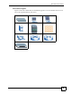
Document Conventions Icons Used in Figures Figures in this User’s Guide may use the following generic icons. The ZyXEL Device icon is not an exact representation of your device.
Safety Warnings Safety Warnings 1 For your safety, be sure to read and follow all warning notices and instructions. • Do NOT use this product near water, for example, in a wet basement or near a swimming pool. • Do NOT expose your device to dampness, dust or corrosive liquids. • Do NOT store things on the device. • Do NOT install, use, or service this device during a thunderstorm. There is a remote risk of electric shock from lightning. • Connect ONLY suitable accessories to the device.
Safety Warnings ZyXEL NBG-334SH User’s Guide 7
Safety Warnings 8 ZyXEL NBG-334SH User’s Guide
Contents Overview Contents Overview Introduction ............................................................................................................................ 27 Getting to Know Your ZyXEL Device ......................................................................................... 29 Wireless Tutorial ........................................................................................................................ 33 Introducing the Web Configurator ................................
Contents Overview 10 ZyXEL NBG-334SH User’s Guide
Table of Contents Table of Contents About This User's Guide .......................................................................................................... 3 Document Conventions............................................................................................................ 4 Safety Warnings........................................................................................................................ 6 Contents Overview .......................................................
Table of Contents 3.4 Navigating the Web Configurator ...................................................................................... 43 3.4.1 The Status Screen ..................................................................................................... 43 3.4.2 Navigation Panel ........................................................................................................ 46 3.5 Summary: Any IP Table ................................................................................
Table of Contents 5.2.2 MAC Address Filter .................................................................................................... 74 5.2.3 User Authentication .................................................................................................... 74 5.2.4 Encryption .................................................................................................................. 75 5.3 Quality of Service .............................................................................
Table of Contents 8.2 DHCP Server General Screen ........................................................................................... 105 8.3 DHCP Server Advanced Screen .................................................................................... 106 8.4 Client List Screen .............................................................................................................. 107 Chapter 9 Network Address Translation (NAT)..............................................................
Table of Contents 12.6 Customizing Keyword Blocking URL Checking ............................................................... 130 12.6.1 Domain Name or IP Address URL Checking ......................................................... 130 12.6.2 Full Path URL Checking ......................................................................................... 130 12.6.3 File Name URL Checking .......................................................................................
Table of Contents 16.1.2 NAT Traversal ........................................................................................................ 155 16.1.3 Cautions with UPnP ............................................................................................... 155 16.2 UPnP and ZyXEL ............................................................................................................ 156 16.3 UPnP Screen ........................................................................................
Table of Contents Appendix A Product Specifications....................................................................................... 203 Appendix B Pop-up Windows, JavaScripts and Java Permissions ...................................... 207 Appendix C IP Addresses and Subnetting ........................................................................... 213 Appendix D Wall-mounting Instructions................................................................................
Table of Contents 18 ZyXEL NBG-334SH User’s Guide
List of Figures List of Figures Figure 1 Secure Internet Access via Cable, DSL or Wireless Modem ................................................... 30 Figure 2 WLAN Application Example ..................................................................................................... 30 Figure 3 Front Panel ............................................................................................................................... 31 Figure 4 AP: Wireless LAN > General ................................
List of Figures Figure 39 Connection Wizard Save ....................................................................................................... 69 Figure 40 Connection Wizard Complete ................................................................................................. 69 Figure 41 Example of a Wireless Network ............................................................................................. 73 Figure 42 Wireless General ......................................................
List of Figures Figure 82 Bandwidth Management: Monitor ......................................................................................... 147 Figure 83 WWW Remote Management ................................................................................................ 150 Figure 84 Telnet Configuration on a TCP/IP Network ........................................................................... 151 Figure 85 Telnet Remote Management ...............................................................
List of Figures Figure 125 Network Number and Host ID ............................................................................................ 214 Figure 126 Subnetting Example: Before Subnetting ............................................................................ 216 Figure 127 Subnetting Example: After Subnetting ............................................................................... 217 Figure 128 Wall-mounting Example ..................................................................
List of Tables List of Tables Table 1 Front Panel LEDs ...................................................................................................................... 31 Table 2 Status Screen Icon Key ............................................................................................................. 44 Table 3 Web Configurator Status Screen ........................................................................................... 45 Table 4 Screens Summary ..............................
List of Tables Table 39 DHCP Server General .......................................................................................................... 105 Table 40 DHCP Server Advanced ....................................................................................................... 106 Table 41 Client List .............................................................................................................................. 108 Table 42 NAT General ..............................................
List of Tables Table 82 PKI Logs ............................................................................................................................... 182 Table 83 802.1X Logs .......................................................................................................................... 183 Table 84 ACL Setting Notes ................................................................................................................ 184 Table 85 ICMP Notes ...................................
List of Tables 26 ZyXEL NBG-334SH User’s Guide
P ART I Introduction Getting to Know Your ZyXEL Device (29) Wireless Tutorial (33) Introducing the Web Configurator (41) 27
CHAPTER 1 Getting to Know Your ZyXEL Device This chapter introduces the main features and applications of the ZyXEL Device. 1.1 ZyXEL Device Overview The ZyXEL Device is the ideal secure wireless firewall router for all data passing between the Internet and your Local Area Network. You can configure firewall and/or content filtering for secure Internet access. You can also use media bandwidth management to efficiently manage traffic on your network.
Chapter 1 Getting to Know Your ZyXEL Device Figure 1 Secure Internet Access via Cable, DSL or Wireless Modem 1.2.1.1 Wireless LAN Application Add a wireless LAN to your existing network without expensive network cables. Wireless stations can move freely anywhere in the coverage area and use resources on the wired network. Figure 2 WLAN Application Example 1.3 Ways to Manage the ZyXEL Device Use any of the following methods to manage the ZyXEL Device. • Web Configurator.
Chapter 1 Getting to Know Your ZyXEL Device • Back up the configuration (and make sure you know how to restore it). Restoring an earlier working configuration may be useful if the device becomes unstable or even crashes. If you forget your password, you will have to reset the ZyXEL Device to its factory default settings. If you backed up an earlier configuration file, you would not have to totally re-configure the ZyXEL Device. You could simply restore your last configuration. 1.
Chapter 1 Getting to Know Your ZyXEL Device Table 1 Front Panel LEDs (continued) LED COLOR STATUS DESCRIPTION WLAN Green On The ZyXEL Device is ready, but is not sending/receiving data through the wireless LAN. Blinking The ZyXEL Device is sending/receiving data through the wireless LAN. Off The wireless LAN is not ready or has failed. None WPS 32 This LED is reserved for future firmware release.
CHAPTER 2 Wireless Tutorial This chapter gives you examples of how to set up an access point and wireless client for wireless communication using the following parameters. The wireless clients can access the Internet through an AP wirelessly. 2.1 Example Parameters SSID SSID_Example3 Channel 6 Security WPA-PSK (Pre-Shared Key: ThisismyWPA-PSKpre-sharedkey) 802.11 mode IEEE 802.
Chapter 2 Wireless Tutorial Figure 4 AP: Wireless LAN > General 2 Make sure the Enable Wireless LAN check box is selected. 3 Enter SSID_Example3 as the SSID and select a channel. 4 Set security mode to WPA-PSK and enter ThisismyWPA-PSKpre-sharedkey in the Pre-Shared Key field. Click Apply. 5 Open the Status screen.Verify your wireless and wireless security settings under Device Information and check if the WLAN connection is up under Interface Status.
Chapter 2 Wireless Tutorial Figure 5 AP: Status 6 Click the WLAN Station Status hyperlink in the AP’s Status screen. You can see if any wireless client has connected to the AP. Figure 6 AP: Status: WLAN Station Status 2.3 Configuring the Wireless Client This section describes how to connect the wireless client to a network.
Chapter 2 Wireless Tutorial 2.3.1 Connecting to a Wireless LAN The following sections show you how to join a wireless network using the ZyXEL utility, as in the following diagram. The wireless client is labeled C and the access point is labeled AP. There are three ways to connect the client to an access point. • Configure nothing and leave the wireless client to automatically scan for and connect to any available network that has no wireless security configured. • Manually connect to a network.
Chapter 2 Wireless Tutorial Figure 7 ZyXEL Utility: Security Settings 4 The Confirm Save window appears. Check your settings and click Save to continue. Figure 8 ZyXEL Utility: Confirm Save 5 The ZyXEL utility returns to the Link Info screen while it connects to the wireless network using your settings. When the wireless link is established, the ZyXEL utility icon in the system tray turns green and the Link Info screen displays details of the active connection.
Chapter 2 Wireless Tutorial If you cannot access the web site, try changing the encryption type in the Security Settings screen, check the Troubleshooting section of this User's Guide or contact your network administrator. 2.3.2 Creating and Using a Profile A profile lets you automatically connect to the same wireless network every time you use the wireless client.
Chapter 2 Wireless Tutorial 4 Choose the same encryption method as the AP to which you want to connect (In this example, WPA-PSK). Figure 12 ZyXEL Utility: Profile Security 5 This screen varies depending on the encryption method you selected in the previous screen. Enter the pre-shared key and leave the encryption type at the default setting. Figure 13 ZyXEL Utility: Profile Encryption 6 In the next screen, leave both boxes checked. Figure 14 Profile: Wireless Protocol Settings.
Chapter 2 Wireless Tutorial Figure 15 Profile: Confirm Save 8 Click Activate Now to use the new profile immediately. Otherwise, click the Activate Later button. If you clicked Activate Later, you can select the profile from the list in the Profile screen and click Connect to activate it. " Only one profile can be activated and used at any given time.
CHAPTER 3 Introducing the Web Configurator This chapter describes how to access the ZyXEL Device web configurator and provides an overview of its screens. 3.1 Web Configurator Overview The web configurator is an HTML-based management interface that allows easy setup and management of the ZyXEL Device via Internet browser. Use Internet Explorer 6.0 and later or Netscape Navigator 7.0 and later versions. The recommended screen resolution is 1024 by 768 pixels.
Chapter 3 Introducing the Web Configurator Figure 17 Change Password Screen " The management session automatically times out when the time period set in the Administrator Inactivity Timer field expires (default five minutes). Simply log back into the ZyXEL Device if this happens. 6 Select the setup mode you want to use. • Click Go to Wizard Setup to use the Configuration Wizard for basic Internet and Wireless setup.
Chapter 3 Introducing the Web Configurator 3.3 Resetting the ZyXEL Device If you forget your password or cannot access the web configurator, you will need to use the RESET button at the back of the ZyXEL Device to reload the factory-default configuration file. This means that you will lose all configurations that you had previously saved, and the password will be reset to “1234”. 3.3.1 Procedure to Use the Reset Button 1 Make sure the PWR LED is on.
Chapter 3 Introducing the Web Configurator Figure 18 Web Configurator Status Screen The following table describes the icons shown in the Status screen. Table 2 Status Screen Icon Key ICON DESCRIPTION Select a language from the drop-down list box to have the web configurator display in that language. Click this icon to open a web help page relevant to the screen you are currently configuring. Click this icon to open the setup wizard.
Chapter 3 Introducing the Web Configurator The following table describes the labels shown in the Status screen. Table 3 Web Configurator Status Screen LABEL DESCRIPTION Device Information System Name This is the System Name you enter in the Maintenance > System > General screen. It is for identification purposes. Firmware Version This is the ZyNOS firmware version and the date created. ZyNOS is ZyXEL's proprietary Network Operating System design.
Chapter 3 Introducing the Web Configurator Table 3 Web Configurator Status Screen (continued) LABEL DESCRIPTION - Configuration Mode This shows whether the advanced screens of each feature are turned on (Advanced) or not (Basic). Interface Status Interface This displays the ZyXEL Device port types. The port types are: WAN, LAN and WLAN. Status For the LAN and WAN ports, this field displays Down (line is down) or Up (line is up or connected).
Chapter 3 Introducing the Web Configurator Table 4 Screens Summary LINK WAN LAN DHCP Server NAT DDNS TAB FUNCTION Internet Connection This screen allows you to configure ISP parameters, WAN IP address assignment, DNS servers and the WAN MAC address. Advanced Use this screen to configure other advanced properties. IP Use this screen to configure LAN IP address and subnet mask. IP Alias Use this screen to partition your LAN interface into subnets.
Chapter 3 Introducing the Web Configurator Table 4 Screens Summary LINK UPnP TAB FUNCTION General Use this screen to enable UPnP on the ZyXEL Device. General Use this screen to view and change administrative settings such as system and domain names, password and inactivity timer. Time Setting Use this screen to change your ZyXEL Device’s time and date. View Log Use this screen to view the logs for the categories that you selected.
Chapter 3 Introducing the Web Configurator Figure 20 Summary: BW MGMT Monitor 3.5.2 Summary: DHCP Table DHCP (Dynamic Host Configuration Protocol, RFC 2131 and RFC 2132) allows individual clients to obtain TCP/IP configuration at start-up from a server. You can configure the ZyXEL Device as a DHCP server or disable it. When configured as a server, the ZyXEL Device provides the TCP/IP configuration for the clients.
Chapter 3 Introducing the Web Configurator 3.5.3 Summary: Packet Statistics Click the Packet Statistics (Details...) hyperlink in the Status screen. Read-only information here includes port status and packet specific statistics. Also provided are "system up time" and "poll interval(s)". The Poll Interval(s) field is configurable. Figure 22 Summary: Packet Statistics The following table describes the labels in this screen.
Chapter 3 Introducing the Web Configurator Figure 23 Summary: Wireless Association List The following table describes the labels in this screen. Table 7 Summary: Wireless Association List LABEL DESCRIPTION # This is the index number of an associated wireless station. MAC Address This field displays the MAC address of an associated wireless station. Association Time This field displays the time a wireless station first associated with the ZyXEL Device. Refresh Click Refresh to reload the list.
Chapter 3 Introducing the Web Configurator 52 ZyXEL NBG-334SH User’s Guide
P ART II Wizard Connection Wizard (55) 53
CHAPTER 4 Connection Wizard This chapter provides information on the wizard setup screens in the web configurator. 4.1 Wizard Setup The web configurator’s wizard setup helps you configure your device to access the Internet. Refer to your ISP (Internet Service Provider) checklist in the Quick Start Guide to know what to enter in each field. Leave a field blank if you don’t have that information. 1 After you access the ZyXEL Device web configurator, click the Go to Wizard setup hyperlink.
Chapter 4 Connection Wizard Figure 25 Select a Language 4 Read the on-screen information and click Next. Figure 26 Welcome to the Connection Wizard 4.2 Connection Wizard: STEP 1: System Information System Information contains administrative and system-related information. 4.2.1 System Name System Name is for identification purposes. However, because some ISPs check this name you should enter your computer's "Computer Name". • In Windows 95/98 click Start, Settings, Control Panel, Network.
Chapter 4 Connection Wizard 4.2.2 Domain Name The Domain Name entry is what is propagated to the DHCP clients on the LAN. If you leave this blank, the domain name obtained by DHCP from the ISP is used. While you must enter the host name (System Name) on each individual computer, the domain name can be assigned from the ZyXEL Device via DHCP. Click Next to configure the ZyXEL Device for Internet access. Figure 27 Wizard Step 1: System Information The following table describes the labels in this screen.
Chapter 4 Connection Wizard Figure 28 Wizard Step 2: Wireless LAN The following table describes the labels in this screen. Table 9 Wizard Step 2: Wireless LAN " 58 LABEL DESCRIPTION Name (SSID) Enter a descriptive name (up to 32 printable 7-bit ASCII characters) for the wireless LAN. If you change this field on the ZyXEL Device, make sure all wireless stations use the same SSID in order to access the network. Security Select a Security level from the drop-down list box.
Chapter 4 Connection Wizard 4.3.1 Basic (WEP) Security Choose Basic (WEP) to setup WEP Encryption parameters. Figure 29 Wizard Step 2: Basic (WEP) Security The following table describes the labels in this screen. Table 10 Wizard Step 2: Basic (WEP) Security LABEL DESCRIPTION Passphrase Type a Passphrase (up to 32 printable characters) and click Generate. The ZyXEL Device automatically generates a WEP key. WEP Encryption Select 64-bit WEP or 128-bit WEP to allow data encryption.
Chapter 4 Connection Wizard Table 10 Wizard Step 2: Basic (WEP) Security LABEL DESCRIPTION Next Click Next to proceed to the next screen. Exit Click Exit to close the wizard screen without saving. 4.3.2 Extend (WPA-PSK or WPA2-PSK) Security Choose Extend (WPA-PSK) or Extend (WPA2-PSK) security in the Wireless LAN setup screen to set up a Pre-Shared Key. Figure 30 Wizard Step 2: Extend (WPA-PSK or WPA2-PSK) Security The following table describes the labels in this screen.
Chapter 4 Connection Wizard Figure 31 Wizard Step 3: ISP Parameters. The following table describes the labels in this screen, Table 12 Wizard Step 3: ISP Parameters CONNECTION TYPE DESCRIPTION Ethernet Select the Ethernet option when the WAN port is used as a regular Ethernet. PPPoE Select the PPP over Ethernet option for a dial-up connection. If your ISP gave you a an IP address and/or subnet mask, then select PPTP. PPTP Select the PPTP option for a dial-up connection. 4.4.
Chapter 4 Connection Wizard One of the benefits of PPPoE is the ability to let end users access one of multiple network services, a function known as dynamic service selection. This enables the service provider to easily create and offer new IP services for specific users. Operationally, PPPoE saves significant effort for both the subscriber and the ISP/carrier, as it requires no specific configuration of the broadband modem at the subscriber’s site.
Chapter 4 Connection Wizard " The ZyXEL Device supports one PPTP server connection at any given time. Figure 34 Wizard Step 3: PPTP Connection The following table describes the fields in this screen Table 14 Wizard Step 3: PPTP Connection LABEL DESCRIPTION ISP Parameters for Internet Access Connection Type Select PPTP from the drop-down list box. To configure a PPTP client, you must configure the User Name and Password fields for a PPP connection and the PPTP parameters for a PPTP connection.
Chapter 4 Connection Wizard Table 14 Wizard Step 3: PPTP Connection LABEL DESCRIPTION Next Click Next to continue. Exit Click Exit to close the wizard screen without saving. 4.4.4 Your IP Address The following wizard screen allows you to assign a fixed IP address or give the ZyXEL Device an automatically assigned IP address depending on your ISP.
Chapter 4 Connection Wizard You can obtain your IP address from the IANA, from an ISP or have it assigned by a private network. If you belong to a small organization and your Internet access is through an ISP, the ISP can provide you with the Internet addresses for your local networks. On the other hand, if you are part of a much larger organization, you should consult your network administrator for the appropriate IP addresses.
Chapter 4 Connection Wizard 2 If the ISP did not give you DNS server information, leave the DNS Server fields set to 0.0.0.0 in the Wizard screen and/or set to From ISP in the WAN > Internet Connection screen for the ISP to dynamically assign the DNS server IP addresses. 4.4.8 WAN IP and DNS Server Address Assignment The following wizard screen allows you to assign a fixed WAN IP address and DNS server addresses.
Chapter 4 Connection Wizard 4.4.9 WAN MAC Address Every Ethernet device has a unique MAC (Media Access Control) address. The MAC address is assigned at the factory and consists of six pairs of hexadecimal characters, for example, 00:A0:C5:00:00:02. Table 18 Example of Network Properties for LAN Servers with Fixed IP Addresses Choose an IP address 192.168.1.2-192.168.1.32; 192.168.1.65-192.168.1.254. Subnet mask 255.255.255.0 Gateway (or default route) 192.168.1.
Chapter 4 Connection Wizard 4.5 Connection Wizard: STEP 4: Bandwidth management Bandwidth management allows you to control the amount of bandwidth going out through the ZyXEL Device’s WAN, LAN or WLAN port and prioritize the distribution of the bandwidth according to the traffic type. This helps keep one service from using all of the available bandwidth and shutting out other users. Figure 38 Wizard Step 4: Bandwidth Management The following fields describe the label in this screen.
Chapter 4 Connection Wizard Figure 39 Connection Wizard Save Follow the on-screen instructions and click Finish to complete the wizard setup. Figure 40 Connection Wizard Complete Well done! You have successfully set up your ZyXEL Device to operate on your network and access the Internet.
Chapter 4 Connection Wizard 70 ZyXEL NBG-334SH User’s Guide
P ART III Advanced Wireless LAN (73) WAN (89) LAN (99) DHCP Server (105) Network Address Translation (NAT) (109) Dynamic DNS (119) Firewall (121) Content Filtering (127) Static Route Screens (133) Bandwidth Management (137) Remote Management Screens (149) Universal Plug-and-Play (UPnP) (155) 71
CHAPTER 5 Wireless LAN This chapter discusses how to configure the wireless network settings in your ZyXEL Device. See the appendices for more detailed information about wireless networks. 5.1 Wireless Network Overview The following figure provides an example of a wireless network. Figure 41 Example of a Wireless Network The wireless network is the part in the blue circle. In this wireless network, devices A and B are called wireless clients.
Chapter 5 Wireless LAN • Every wireless client in the same wireless network must use security compatible with the AP. Security stops unauthorized devices from using the wireless network. It can also protect the information that is sent in the wireless network. 5.2 Wireless Security Overview The following sections introduce different types of wireless security you can set up in the wireless network. 5.2.1 SSID Normally, the AP acts like a beacon and regularly broadcasts the SSID in the area.
Chapter 5 Wireless LAN If your AP does not provide a local user database and if you do not have a RADIUS server, you cannot set up user names and passwords for your users. Unauthorized devices can still see the information that is sent in the wireless network, even if they cannot use the wireless network. Furthermore, there are ways for unauthorized wireless users to get a valid user name and password. Then, they can use that user name and password to use the wireless network.
Chapter 5 Wireless LAN When you select WPA2 or WPA2-PSK in your ZyXEL Device, you can also select an option (WPA Compatible) to support WPA as well. In this case, if some wireless clients support WPA and some support WPA2, you should set up WPA2-PSK or WPA2 (depending on the type of wireless network login) and select the WPA Compatible option in the ZyXEL Device. Many types of encryption use a key to protect the information in the wireless network. The longer the key, the stronger the encryption.
Chapter 5 Wireless LAN 5.4 General Wireless LAN Screen " If you are configuring the ZyXEL Device from a computer connected to the wireless LAN and you change the ZyXEL Device’s SSID, channel or security settings, you will lose your wireless connection when you press Apply to confirm. You must then change the wireless settings of your computer to match the ZyXEL Device’s new settings. Click Network > Wireless LAN to open the General screen.
Chapter 5 Wireless LAN 5.4.1 No Security Select No Security to allow wireless stations to communicate with the access points without any data encryption. " If you do not enable any wireless security on your ZyXEL Device, your network is accessible to any wireless networking device that is within range. Figure 43 Wireless: No Security The following table describes the labels in this screen. Table 24 Wireless No Security LABEL DESCRIPTION Security Mode Choose No Security from the drop-down list box.
Chapter 5 Wireless LAN Figure 44 Wireless: Static WEP Encryption The following table describes the wireless LAN security labels in this screen. Table 25 Wireless: Static WEP Encryption LABEL DESCRIPTION Passphrase Enter a passphrase (password phrase) of up to 32 printable characters and click Generate. The ZyXEL Device automatically generates four different WEP keys and displays them in the Key fields below. WEP Encryption Select 64-bit WEP or 128-bit WEP to enable data encryption.
Chapter 5 Wireless LAN 5.4.3 WPA-PSK/WPA2-PSK Click Network > Wireless LAN to display the General screen. Figure 45 Wireless: WPA-PSK/WPA2-PSK The following table describes the labels in this screen. Table 26 Wireless: WPA-PSK/WPA2-PSK LABEL DESCRIPTION WPA Compatible This check box is available only when you select WPA2-PSK or WPA2 in the Security Mode field.
Chapter 5 Wireless LAN Table 26 Wireless: WPA-PSK/WPA2-PSK LABEL DESCRIPTION Group Key Update Timer The Group Key Update Timer is the rate at which the AP (if using WPA-PSK/ WPA2-PSK key management) or RADIUS server (if using WPA/WPA2 key management) sends a new group key out to all clients. The re-keying process is the WPA/WPA2 equivalent of automatically changing the WEP key for an AP and all stations in a WLAN on a periodic basis.
Chapter 5 Wireless LAN The following table describes the labels in this screen. Table 27 Wireless: WPA/WPA2 LABEL DESCRIPTION WPA Compatible This check box is available only when you select WPA2-PSK or WPA2 in the Security Mode field. Select the check box to have both WPA2 and WPA wireless clients be able to communicate with the ZyXEL Device even when the ZyXEL Device is using WPA2-PSK or WPA2.
Chapter 5 Wireless LAN 5.5 MAC Filter The MAC filter screen allows you to configure the ZyXEL Device to give exclusive access to up to 32 devices (Allow) or exclude up to 32 devices from accessing the ZyXEL Device (Deny). Every Ethernet device has a unique MAC (Media Access Control) address. The MAC address is assigned at the factory and consists of six pairs of hexadecimal characters, for example, 00:A0:C5:00:00:02. You need to know the MAC address of the devices to configure this screen.
Chapter 5 Wireless LAN Table 28 MAC Address Filter LABEL DESCRIPTION Set This is the index number of the MAC address. MAC Address Enter the MAC addresses of the wireless station that are allowed or denied access to the ZyXEL Device in these address fields. Enter the MAC addresses in a valid MAC address format, that is, six hexadecimal character pairs, for example, 12:34:56:78:9a:bc. Apply Click Apply to save your changes back to the ZyXEL Device.
Chapter 5 Wireless LAN Table 29 Wireless LAN Advanced LABEL DESCRIPTION 802.11 Mode Select 802.11b to allow only IEEE 802.11b compliant WLAN devices to associate with the ZyXEL Device. Select 802.11g to allow only IEEE 802.11g compliant WLAN devices to associate with the ZyXEL Device. Select 802.11b/g to allow either IEEE802.11b or IEEE802.11g compliant WLAN devices to associate with the ZyXEL Device. The transmission rate of your ZyXEL Device might be reduced.
Chapter 5 Wireless LAN Figure 49 Wireless LAN QoS The following table describes the labels in this screen. Table 30 Wireless LAN QoS LABEL DESCRIPTION Enable WMM QoS Select this to turn on WMM QoS (Wireless MultiMedia Quality of Service). The ZyXEL Device assigns priority to packets based on the 802.1q or DSCP information in their headers. If a packet has no WMM information in its header, it is assigned the default priority.
Chapter 5 Wireless LAN Table 30 Wireless LAN QoS (continued) LABEL DESCRIPTION Priority This field displays the priority of the application. Highest - Typically used for voice or video that should be highquality. High - Typically used for voice or video that can be medium-quality. Mid - Typically used for applications that do not fit into another priority. For example, Internet surfing.
Chapter 5 Wireless LAN Table 31 Application Priority Configuration (continued) 88 LABEL DESCRIPTION Service The following is a description of the applications you can prioritize with WMM QoS. Select a service from the drop-down list box. • E-Mail Electronic mail consists of messages sent through a computer network to specific groups or individuals.
CHAPTER 6 WAN This chapter describes how to configure WAN settings. 6.1 WAN Overview See the chapter about the connection wizard for more information on the fields in the WAN screens. 6.2 WAN MAC Address The MAC address screen allows users to configure the WAN port's MAC address by either using the factory default or cloning the MAC address from a computer on your LAN. Choose Factory Default to select the factory assigned default MAC Address.
Chapter 6 WAN The ZyXEL Device supports both IGMP version 1 (IGMP-v1) and IGMP version 2 (IGMPv2). At start up, the ZyXEL Device queries all directly connected networks to gather group membership. After that, the ZyXEL Device periodically updates this information. IP multicasting can be enabled/disabled on the ZyXEL Device LAN and/or WAN interfaces in the web configurator (LAN; WAN). Select None to disable IP multicasting on these interfaces. 6.
Chapter 6 WAN The following table describes the labels in this screen. Table 32 Ethernet Encapsulation LABEL DESCRIPTION Encapsulation You must choose the Ethernet option when the WAN port is used as a regular Ethernet. Service Type Choose from Standard, RR-Telstra (RoadRunner Telstra authentication method), RR-Manager (Roadrunner Manager authentication method), RRToshiba (Roadrunner Toshiba authentication method) or Telia Login. The following fields do not appear with the Standard service type.
Chapter 6 WAN Table 32 Ethernet Encapsulation LABEL DESCRIPTION Set WAN MAC Address Select this option and enter the MAC address you want to use. Apply Click Apply to save your changes back to the ZyXEL Device. Reset Click Reset to begin configuring this screen afresh. 6.4.2 PPPoE Encapsulation The ZyXEL Device supports PPPoE (Point-to-Point Protocol over Ethernet).
Chapter 6 WAN Figure 52 PPPoE Encapsulation The following table describes the labels in this screen. Table 33 PPPoE Encapsulation LABEL DESCRIPTION ISP Parameters for Internet Access Encapsulation The PPP over Ethernet choice is for a dial-up connection using PPPoE. The ZyXEL Device supports PPPoE (Point-to-Point Protocol over Ethernet). PPPoE is an IETF Draft standard (RFC 2516) specifying how a personal computer (PC) interacts with a broadband modem (i.e. xDSL, cable, wireless, etc.) connection.
Chapter 6 WAN Table 33 PPPoE Encapsulation LABEL DESCRIPTION Retype to Confirm Type your password again to make sure that you have entered is correctly. Nailed-Up Connection Select Nailed-Up Connection if you do not want the connection to time out. Idle Timeout This value specifies the time in seconds that elapses before the router automatically disconnects from the PPPoE server.
Chapter 6 WAN PPTP supports on-demand, multi-protocol and virtual private networking over public networks, such as the Internet. This screen displays when you select PPTP encapsulation.
Chapter 6 WAN The following table describes the labels in this screen. Table 34 PPTP Encapsulation LABEL DESCRIPTION ISP Parameters for Internet Access Encapsulation Point-to-Point Tunneling Protocol (PPTP) is a network protocol that enables secure transfer of data from a remote client to a private server, creating a Virtual Private Network (VPN) using TCP/IP-based networks. PPTP supports on-demand, multi-protocol, and virtual private networking over public networks, such as the Internet.
Chapter 6 WAN Table 34 PPTP Encapsulation LABEL DESCRIPTION First DNS Server Second DNS Server Third DNS Server Select From ISP if your ISP dynamically assigns DNS server information (and the ZyXEL Device's WAN IP address). The field to the right displays the (readonly) DNS server IP address that the ISP assigns. Select User-Defined if you have the IP address of a DNS server. Enter the DNS server's IP address in the field to the right. If you chose User-Defined, but leave the IP address set to 0.0.0.
Chapter 6 WAN The following table describes the labels in this screen. Table 35 WAN > Advanced LABEL DESCRIPTION Multicast Setup Multicast Select IGMP V-1, IGMP V-2 or None. IGMP (Internet Group Multicast Protocol) is a network-layer protocol used to establish membership in a Multicast group - it is not used to carry user data. IGMP version 2 (RFC 2236) is an improvement over version 1 (RFC 1112) but IGMP version 1 is still in wide use.
CHAPTER 7 LAN This chapter describes how to configure LAN settings. 7.1 LAN Overview A Local Area Network (LAN) is a shared communication system to which many computers are attached. A LAN is a computer network limited to the immediate area, usually the same building or floor of a building. The LAN screens can help you configure a LAN DHCP server, manage IP addresses, and partition your physical network into logical networks. 7.1.
Chapter 7 LAN 7.2.2 IP Address and Subnet Mask Refer to the IP address and subnet mask section in the Connection Wizard chapter for this information. 7.2.3 Multicast Traditionally, IP packets are transmitted in one of either two ways - Unicast (1 sender - 1 recipient) or Broadcast (1 sender - everybody on the network). Multicast delivers IP packets to a group of hosts on the network - not everybody and not just 1.
Chapter 7 LAN Figure 55 Any IP Example The Any IP feature does not apply to a computer using either a dynamic IP address or a static IP address that is in the same subnet as the ZyXEL Device’s IP address. " You must enable NAT to use the Any IP feature on the ZyXEL Device. Address Resolution Protocol (ARP) is a protocol for mapping an Internet Protocol address (IP address) to a physical machine address, also known as a Media Access Control or MAC address, on the local area network.
Chapter 7 LAN 7.3 LAN IP Screen Use this screen to change your basic LAN settings. Click Network > LAN. Figure 56 LAN IP The following table describes the labels in this screen. Table 36 LAN IP LABEL DESCRIPTION LAN TCP/IP IP Address Type the IP address of your ZyXEL Device in dotted decimal notation 192.168.1.1 (factory default). IP Subnet Mask The subnet mask specifies the network number portion of an IP address.
Chapter 7 LAN Figure 57 LAN IP Alias The following table describes the labels in this screen. Table 37 LAN IP Alias LABEL DESCRIPTION IP Alias 1,2 Select the check box to configure another LAN network for the ZyXEL Device. IP Address Enter the IP address of your ZyXEL Device in dotted decimal notation. IP Subnet Mask Your ZyXEL Device will automatically calculate the subnet mask based on the IP address that you assign.
Chapter 7 LAN Figure 58 Advanced LAN The following table describes the labels in this screen. Table 38 Advanced LAN LABEL DESCRIPTION Multicast Select IGMP V-1 or IGMP V-2 or None. IGMP (Internet Group Multicast Protocol) is a network-layer protocol used to establish membership in a Multicast group - it is not used to carry user data. IGMP version 2 (RFC 2236) is an improvement over version 1 (RFC 1112) but IGMP version 1 is still in wide use.
CHAPTER 8 DHCP Server 8.1 DHCP DHCP (Dynamic Host Configuration Protocol, RFC 2131 and RFC 2132) allows individual clients to obtain TCP/IP configuration at start-up from a server. You can configure the ZyXEL Device as a DHCP server or disable it. When configured as a server, the ZyXEL Device provides the TCP/IP configuration for the clients. If DHCP service is disabled, you must have another DHCP server on your LAN, or else the computer must be manually configured. 8.
Chapter 8 DHCP Server 8.3 DHCP Server Advanced Screen This screen allows you to assign IP addresses on the LAN to specific individual computers based on their MAC addresses. You can also use this screen to configure the DNS server information that the ZyXEL Device sends to the DHCP clients. Every Ethernet device has a unique MAC (Media Access Control) address. The MAC address is assigned at the factory and consists of six pairs of hexadecimal characters, for example, 00:A0:C5:00:00:02.
Chapter 8 DHCP Server Table 40 DHCP Server Advanced LABEL DESCRIPTION First DNS Server Second DNS Server Third DNS Server Select From ISP if your ISP dynamically assigns DNS server information (and the ZyXEL Device's WAN IP address). The field to the right displays the (readonly) DNS server IP address that the ISP assigns. Select User-Defined if you have the IP address of a DNS server. Enter the DNS server's IP address in the field to the right.
Chapter 8 DHCP Server The following table describes the labels in this screen. Table 41 Client List 108 LABEL DESCRIPTION # This is the index number of the host computer. IP Address This field displays the IP address relative to the # field listed above. Host Name This field displays the computer host name. MAC Address The MAC (Media Access Control) or Ethernet address on a LAN (Local Area Network) is unique to your computer (six pairs of hexadecimal notation).
CHAPTER 9 Network Address Translation (NAT) This chapter discusses how to configure NAT on the ZyXEL Device. 9.1 NAT Overview NAT (Network Address Translation - NAT, RFC 1631) is the translation of the IP address of a host in a packet. For example, the source address of an outgoing packet, used within one network is changed to a different IP address known within another network. 9.
Chapter 9 Network Address Translation (NAT) " Many residential broadband ISP accounts do not allow you to run any server processes (such as a Web or FTP server) from your location. Your ISP may periodically check for servers and may suspend your account if it discovers any active services at your location. If you are unsure, refer to your ISP. 9.2.
Chapter 9 Network Address Translation (NAT) The following table describes the labels in this screen. Table 42 NAT General LABEL DESCRIPTION Network Address Translation Network Address Translation (NAT) allows the translation of an Internet protocol address used within one network (for example a private IP address used in a local network) to a different IP address known within another network (for example a public IP address used on the Internet). Select the check box to enable NAT.
Chapter 9 Network Address Translation (NAT) Figure 64 NAT Application The following table describes the labels in this screen. Table 43 NAT Application LABEL DESCRIPTION Game List Update A game list includes the pre-defined service name(s) and port number(s). You can edit and upload it to the ZyXEL Device to replace the existing entries in the second field next to Service Name. File Path Type in the location of the file you want to upload in this field or click Browse... to find it. Browse...
Chapter 9 Network Address Translation (NAT) Table 43 NAT Application (continued) LABEL DESCRIPTION Port Type a port number(s) to be forwarded. To specify a range of ports, enter a hyphen (-) between the first port and the last port, such as 10-20. To specify two or more non-consecutive port numbers, separate them by a comma without spaces, such as 123,567. Server IP Address Type the inside IP address of the server that receives packets from the port(s) specified in the Port field.
Chapter 9 Network Address Translation (NAT) Figure 65 Game List Example version=1 1;name=Battlefield 1942;port=14567,22000,23000-23009,27900,28900 2;name=Call of Duty;port=28960 3;name=Civilization IV;port=2056 4;name=Diablo I and II;port=6112-6119,4000 5;name=Doom 3;port=27666 6;name=F.E.A.
Chapter 9 Network Address Translation (NAT) Figure 66 Trigger Port Forwarding Process: Example 1 Jane requests a file from the Real Audio server (port 7070). 2 Port 7070 is a “trigger” port and causes the ZyXEL Device to record Jane’s computer IP address. The ZyXEL Device associates Jane's computer IP address with the "incoming" port range of 6970-7170. 3 The Real Audio server responds using a port number ranging between 6970-7170. 4 The ZyXEL Device forwards the traffic to Jane’s computer IP address.
Chapter 9 Network Address Translation (NAT) Figure 67 NAT Advanced The following table describes the labels in this screen. Table 44 NAT Advanced LABEL DESCRIPTION Max NAT/Firewall Session Per User Type a number ranging from 1 to 2048 to limit the number of NAT/firewall sessions that a host can create. When computers use peer to peer applications, such as file sharing applications, they may use a large number of NAT sessions.
Chapter 9 Network Address Translation (NAT) Table 44 NAT Advanced LABEL End Port Trigger DESCRIPTION Type a port number or the ending port number in a range of port numbers. The trigger port is a port (or a range of ports) that causes (or triggers) the ZyXEL Device to record the IP address of the LAN computer that sent the traffic to a server on the WAN. Start Port Type a port number or the starting port number in a range of port numbers.
Chapter 9 Network Address Translation (NAT) 118 ZyXEL NBG-334SH User’s Guide
CHAPTER 10 Dynamic DNS 10.1 Dynamic DNS Introduction Dynamic DNS allows you to update your current dynamic IP address with one or many dynamic DNS services so that anyone can contact you (in NetMeeting, CU-SeeMe, etc.). You can also access your FTP server or Web site on your own computer using a domain name (for instance myhost.dhs.org, where myhost is a name of your choice) that will never change instead of using an IP address that changes each time you reconnect.
Chapter 10 Dynamic DNS Figure 68 Dynamic DNS The following table describes the labels in this screen. Table 45 Dynamic DNS LABEL DESCRIPTION Enable Dynamic DNS Select this check box to use dynamic DNS. Service Provider Select the name of your Dynamic DNS service provider. Dynamic DNS Type Select the type of service that you are registered for from your Dynamic DNS service provider. Host Name Enter a host names in the field provided.
CHAPTER 11 Firewall This chapter gives some background information on firewalls and explains how to get started with the ZyXEL Device’s firewall. 11.1 Introduction to ZyXEL’s Firewall 11.1.1 What is a Firewall? Originally, the term “firewall” referred to a construction technique designed to prevent the spread of fire from one room to another. The networking term "firewall" is a system or group of systems that enforces an access-control policy between two networks.
Chapter 11 Firewall The ZyXEL Device is installed between the LAN and a broadband modem connecting to the Internet. This allows it to act as a secure gateway for all data passing between the Internet and the LAN. The ZyXEL Device has one Ethernet WAN port and four Ethernet LAN ports, which are used to physically separate the network into two areas.The WAN (Wide Area Network) port attaches to the broadband (cable or DSL) modem to the Internet.
Chapter 11 Firewall 1 A computer on the LAN initiates a connection by sending a SYN packet to a receiving server on the WAN. 2 The ZyXEL Device reroutes the packet to Gateway A, which is in Subnet 2. 3 The reply from the WAN goes to the ZyXEL Device. 4 The ZyXEL Device then sends it to the computer on the LAN in Subnet 1. Figure 69 Using IP Alias to Solve the Triangle Route Problem 11.3 General Firewall Screen Click Security > Firewall to open the General screen.
Chapter 11 Firewall Table 46 Firewall General LABEL DESCRIPTION Log Select whether to create a log for packets that are traveling in the selected direction when the packets are blocked or forwarded. To log packets related to firewall rules, make sure that Access Control under Log is selected in the Logs > Log Settings screen. Apply Click Apply to save the settings. Reset Click Reset to start configuring this screen again. 11.4 Services Screen Click Security > Firewall > Services.
Chapter 11 Firewall Figure 71 Firewall Services The following table describes the labels in this screen. Table 47 Firewall Services LABEL DESCRIPTION ICMP Internet Control Message Protocol is a message control and error-reporting protocol between a host server and a gateway to the Internet. ICMP uses Internet Protocol (IP) datagrams, but the messages are processed by the TCP/IP software and directly apparent to the application user.
Chapter 11 Firewall Table 47 Firewall Services 126 LABEL DESCRIPTION Do not respond to requests for unauthorized services Select this option to prevent hackers from finding the ZyXEL Device by probing for unused ports. If you select this option, the ZyXEL Device will not respond to port request(s) for unused ports, thus leaving the unused ports and the ZyXEL Device unseen.
CHAPTER 12 Content Filtering This chapter provides a brief overview of content filtering using the embedded web GUI. 12.1 Introduction to Content Filtering Internet content filtering allows you to create and enforce Internet access policies tailored to your needs. Content filtering is the ability to block certain web features or specific URL keywords. 12.2 Restrict Web Features The ZyXEL Device can block web features such as ActiveX controls, Java applets, cookies and disable web proxies. 12.
Chapter 12 Content Filtering Figure 72 Content Filter: Filter The following table describes the labels in this screen. Table 48 Content Filter: Filter 128 LABEL DESCRIPTION Trusted Computer IP Address To enable this feature, type an IP address of any one of the computers in your network that you want to have as a trusted computer. This allows the trusted computer to have full access to all features that are configured to be blocked by content filtering.
Chapter 12 Content Filtering Table 48 Content Filter: Filter LABEL DESCRIPTION Keyword Type a keyword in this field. You may use any character (up to 64 characters). Wildcards are not allowed. You can also enter a numerical IP address. Keyword List This list displays the keywords already added. Add Click Add after you have typed a keyword. Repeat this procedure to add other keywords. Up to 64 keywords are allowed.
Chapter 12 Content Filtering The following table describes the labels in this screen. Table 49 Content Filter: Schedule LABEL DESCRIPTION Day to Block Select check boxes for the days that you want the ZyXEL Device to perform content filtering. Select the Everyday check box to have content filtering turned on all days of the week. Time of Day to Block (24-Hour Format) Time of Day to Block allows the administrator to define during which time periods content filtering is enabled.
Chapter 12 Content Filtering For example, filename URL checking searches for keywords within the URL www.zyxel.com.tw/news/pressroom.php. Use the ip urlfilter customize actionFlags 8 [disable | enable] command to extend (or not extend) the keyword blocking search to include the URL's complete filename.
Chapter 12 Content Filtering 132 ZyXEL NBG-334SH User’s Guide
CHAPTER 13 Static Route Screens This chapter shows you how to configure static routes for your ZyXEL Device. 13.1 Static Route Overview Each remote node specifies only the network to which the gateway is directly connected, and the ZyXEL Device has no knowledge of the networks beyond. For instance, the ZyXEL Device knows about network N2 in the following figure through remote node router R1.
Chapter 13 Static Route Screens Figure 75 IP Static Route The following table describes the labels in this screen. Table 50 IP Static Route LABEL DESCRIPTION # This is the index number of an individual static route. The first entry is for the default route and not editable. Name This is the name that describes or identifies this route. Active This icon is turned on when this static route is active.
Chapter 13 Static Route Screens Figure 76 Static Route Setup The following table describes the labels in this screen. Table 51 Static Route Setup LABEL DESCRIPTION Route Name Enter the name of the IP static route. Leave this field blank to delete this static route. Active This field allows you to activate/deactivate this static route. Private This parameter determines if the ZyXEL Device will include this route to a remote node in its RIP broadcasts.
Chapter 13 Static Route Screens 136 ZyXEL NBG-334SH User’s Guide
CHAPTER 14 Bandwidth Management This chapter contains information about configuring bandwidth management, editing rules and viewing the ZyXEL Device’s bandwidth management logs. 14.1 Bandwidth Management Overview ZyXEL’s Bandwidth Management allows you to specify bandwidth management rules based on an application and/or subnet. You can allocate specific amounts of bandwidth capacity (bandwidth budgets) to different bandwidth rules.
Chapter 14 Bandwidth Management The following figure shows LAN subnets. You could configure one bandwidth class for subnet A and another for subnet B. Figure 77 Subnet-based Bandwidth Management Example 14.4 Application and Subnet-based Bandwidth Management You could also create bandwidth classes based on a combination of a subnet and an application. The following example table shows bandwidth allocations for application specific traffic from separate LAN subnets.
Chapter 14 Bandwidth Management Table 53 Bandwidth Management Priorities PRIORITY LEVELS: TRAFFIC WITH A HIGHER PRIORITY GETS THROUGH FASTER WHILE TRAFFIC WITH A LOWER PRIORITY IS DROPPED IF THE NETWORK IS CONGESTED. Mid Typically used for “excellent effort” or better than best effort and would include important business traffic that can tolerate some delay.
Chapter 14 Bandwidth Management 14.6.1 Services and Port Numbers The commonly used services and port numbers are shown in the following table. Please refer to RFC 1700 for further information about port numbers. Next to the name of the service, two fields appear in brackets. The first field indicates the IP protocol type (TCP, UDP, or ICMP). The second field indicates the IP port number that defines the service. (Note that there may be more than one IP protocol type. For example, look at the DNS service.
Chapter 14 Bandwidth Management Table 55 Commonly Used Services SERVICE DESCRIPTION PING(ICMP:0) Packet INternet Groper is a protocol that sends out ICMP echo requests to test whether or not a remote host is reachable. POP3(TCP:110) Post Office Protocol version 3 lets a client computer get e-mail from a POP3 server through a temporary connection (TCP/IP or other). PPTP(TCP:1723) Point-to-Point Tunneling Protocol enables secure transfer of data over public networks. This is the control channel.
Chapter 14 Bandwidth Management 14.7 Default Bandwidth Management Classes and Priorities If you enable bandwidth management but do not configure a rule for critical traffic like VoIP, the voice traffic may then get delayed due to insufficient bandwidth. With the automatic traffic classifier feature activated, the ZyXEL Device automatically assigns a default bandwidth management class and priority to traffic that does not match any of the user-defined rules.
Chapter 14 Bandwidth Management The following table describes the labels in this screen. Table 57 Bandwidth Management: General LABEL DESCRIPTION Enable Bandwidth Management Select this check box to have the ZyXEL Device apply bandwidth management. Enable bandwidth management to give traffic that matches a bandwidth rule priority over traffic that does not match a bandwidth rule.
Chapter 14 Bandwidth Management The following table describes the labels in this screen. Table 58 Bandwidth Management: Advanced LABEL DESCRIPTION Upstream Bandwidth (kbps) Enter the amount of bandwidth in kbps (2 to 100,000) that you want to allocate for traffic. 20 kbps to 20,000 kbps is recommended. The recommendation is to set this speed to be equal to or less than the speed of the broadband device connected to the WAN port.
Chapter 14 Bandwidth Management Figure 80 Bandwidth Management Rule Configuration: Pre-defined Service The following table describes the labels in this screen. Table 59 Bandwidth Management Rule Configuration: Pre-defined Service LABEL DESCRIPTION # This is the number of an individual bandwidth management rule. Enable Select an interface’s check box to enable bandwidth management on that interface. Direction These read-only labels represent the physical interfaces.
Chapter 14 Bandwidth Management Figure 81 Bandwidth Management Rule Configuration: User-defined Service The following table describes the labels in this screen. Table 60 Bandwidth Management Rule Configuration: User-defined Service LABEL DESCRIPTION BW Budget Select Maximum Bandwidth or Minimum Bandwidth and specify the maximum or minimum bandwidth allowed for the rule in kilobits per second. Destination Address Enter the destination IP address in dotted decimal notation.
Chapter 14 Bandwidth Management Figure 82 Bandwidth Management: Monitor ZyXEL NBG-334SH User’s Guide 147
Chapter 14 Bandwidth Management 148 ZyXEL NBG-334SH User’s Guide
CHAPTER 15 Remote Management Screens This chapter provides information on the Remote Management screens. 15.1 Remote Management Overview Remote management allows you to determine which services/protocols can access which ZyXEL Device interface (if any) from which computers. " When you configure remote management to allow management from the WAN, you still need to configure a firewall rule to allow access. See the firewall chapters for details on configuring firewall rules.
Chapter 15 Remote Management Screens 15.1.1 Remote Management Limitations Remote management over LAN or WAN will not work when: 1 You have disabled that service in one of the remote management screens. 2 The IP address in the Secured Client IP Address field does not match the client IP address. If it does not match, the ZyXEL Device will disconnect the session immediately. 3 There is already another remote management session with an equal or higher priority running.
Chapter 15 Remote Management Screens The following table describes the labels in this screen. Table 62 WWW Remote Management LABEL DESCRIPTION Server Port You may change the server port number for a service if needed, however you must use the same port number in order to use that service for remote management. Server Access Select the interface(s) through which a computer may access the ZyXEL Device using this service.
Chapter 15 Remote Management Screens Figure 85 Telnet Remote Management The following table describes the labels in this screen. Table 63 Telnet Remote Management LABEL DESCRIPTION Server Port You may change the server port number for a service if needed, however you must use the same port number in order to use that service for remote management. Server Access Select the interface(s) through which a computer may access the ZyXEL Device using this service.
Chapter 15 Remote Management Screens The following table describes the labels in this screen. Table 64 FTP Remote Management LABEL DESCRIPTION Server Port You may change the server port number for a service if needed, however you must use the same port number in order to use that service for remote management. Server Access Select the interface(s) through which a computer may access the ZyXEL Device using this service.
Chapter 15 Remote Management Screens The following table describes the labels in this screen. Table 65 DNS Remote Management 154 LABEL DESCRIPTION Server Port The DNS service port number is 53 and cannot be changed here. Server Access Select the interface(s) through which a computer may send DNS queries to the ZyXEL Device. Secured Client IP Address A secured client is a “trusted” computer that is allowed to send DNS queries to the ZyXEL Device.
CHAPTER 16 Universal Plug-and-Play (UPnP) This chapter introduces the UPnP feature in the web configurator. 16.1 Introducing Universal Plug and Play Universal Plug and Play (UPnP) is a distributed, open networking standard that uses TCP/IP for simple peer-to-peer network connectivity between devices. A UPnP device can dynamically join a network, obtain an IP address, convey its capabilities and learn about other devices on the network.
Chapter 16 Universal Plug-and-Play (UPnP) When a UPnP device joins a network, it announces its presence with a multicast message. For security reasons, the ZyXEL Device allows multicast messages on the LAN only. All UPnP-enabled devices may communicate freely with each other without additional configuration. Disable UPnP if this is not your intention. 16.2 UPnP and ZyXEL ZyXEL has achieved UPnP certification from the Universal Plug and Play Forum UPnP™ Implementers Corp. (UIC).
Chapter 16 Universal Plug-and-Play (UPnP) Table 66 Configuring UPnP LABEL DESCRIPTION Apply Click Apply to save the setting to the ZyXEL Device. Cancel Click Cancel to return to the previously saved settings. 16.4 Installing UPnP in Windows Example This section shows how to install UPnP in Windows Me and Windows XP. 16.4.0.1 Installing UPnP in Windows Me Follow the steps below to install the UPnP in Windows Me. 1 Click Start and Control Panel. Double-click Add/Remove Programs.
Chapter 16 Universal Plug-and-Play (UPnP) Figure 90 Add/Remove Programs: Windows Setup: Communication: Components 4 Click OK to go back to the Add/Remove Programs Properties window and click Next. 5 Restart the computer when prompted. Installing UPnP in Windows XP Follow the steps below to install the UPnP in Windows XP. 1 Click Start and Control Panel. 2 Double-click Network Connections. 3 In the Network Connections window, click Advanced in the main menu and select Optional Networking Components ….
Chapter 16 Universal Plug-and-Play (UPnP) Figure 92 Windows Optional Networking Components Wizard 5 In the Networking Services window, select the Universal Plug and Play check box. Figure 93 Networking Services 6 Click OK to go back to the Windows Optional Networking Component Wizard window and click Next.
Chapter 16 Universal Plug-and-Play (UPnP) 16.4.0.2 Using UPnP in Windows XP Example This section shows you how to use the UPnP feature in Windows XP. You must already have UPnP installed in Windows XP and UPnP activated on the ZyXEL Device. Make sure the computer is connected to a LAN port of the ZyXEL Device. Turn on your computer and the ZyXEL Device. Auto-discover Your UPnP-enabled Network Device 1 Click Start and Control Panel. Double-click Network Connections. An icon displays under Internet Gateway.
Chapter 16 Universal Plug-and-Play (UPnP) Figure 95 Internet Connection Properties 4 You may edit or delete the port mappings or click Add to manually add port mappings.
Chapter 16 Universal Plug-and-Play (UPnP) Figure 96 Internet Connection Properties: Advanced Settings Figure 97 Internet Connection Properties: Advanced Settings: Add 5 When the UPnP-enabled device is disconnected from your computer, all port mappings will be deleted automatically. 6 Select Show icon in notification area when connected option and click OK. An icon displays in the system tray.
Chapter 16 Universal Plug-and-Play (UPnP) Figure 98 System Tray Icon 7 Double-click on the icon to display your current Internet connection status. Figure 99 Internet Connection Status Web Configurator Easy Access With UPnP, you can access the web-based configurator on the ZyXEL Device without finding out the IP address of the ZyXEL Device first. This comes helpful if you do not know the IP address of the ZyXEL Device. Follow the steps below to access the web configurator.
Chapter 16 Universal Plug-and-Play (UPnP) Figure 100 Network Connections 4 An icon with the description for each UPnP-enabled device displays under Local Network. 5 Right-click on the icon for your ZyXEL Device and select Invoke. The web configurator login screen displays.
Chapter 16 Universal Plug-and-Play (UPnP) Figure 101 Network Connections: My Network Places 6 Right-click on the icon for your ZyXEL Device and select Properties. A properties window displays with basic information about the ZyXEL Device.
Chapter 16 Universal Plug-and-Play (UPnP) 166 ZyXEL NBG-334SH User’s Guide
P ART IV Maintenance and Troubleshooting System (169) Logs (173) Tools (187) Configuration Mode (193) Troubleshooting (195) 167
CHAPTER 17 System This chapter provides information on the System screens. 17.1 System Overview See the chapter about wizard setup for more information on the next few screens. 17.2 System General Screen Click Maintenance > System. The following screen displays.
Chapter 17 System The following table describes the labels in this screen. Table 67 System General LABEL DESCRIPTION System Name System Name is a unique name to identify the ZyXEL Device in an Ethernet network. It is recommended you enter your computer’s “Computer name” in this field (see the chapter about wizard setup for how to find your computer’s name). This name can be up to 30 alphanumeric characters long. Spaces are not allowed, but dashes “-” and underscores "_" are accepted.
Chapter 17 System Figure 104 Time Setting The following table describes the labels in this screen. Table 68 Time Setting LABEL DESCRIPTION Current Time and Date Current Time This field displays the time of your ZyXEL Device. Each time you reload this page, the ZyXEL Device synchronizes the time with the time server. Current Date This field displays the date of your ZyXEL Device. Each time you reload this page, the ZyXEL Device synchronizes the date with the time server.
Chapter 17 System Table 68 Time Setting LABEL DESCRIPTION Get from Time Server Select this radio button to have the ZyXEL Device get the time and date from the time server you specified below. Auto Select Auto to have the ZyXEL Device automatically search for an available time server and synchronize the date and time with the time server after you click Apply.
CHAPTER 18 Logs This chapter contains information about configuring general log settings and viewing the ZyXEL Device’s logs. Refer to the appendices for example log message explanations. 18.1 View Log The web configurator allows you to look at all of the ZyXEL Device’s logs in one location. Click Maintenance > Logs to open the View Log screen. Use the View Log screen to see the logs for the categories that you selected in the Log Settings screen (see Section 18.2 on page 174).
Chapter 18 Logs The following table describes the labels in this screen. Table 69 View Log LABEL DESCRIPTION Display The categories that you select in the Log Settings page (see Section 18.2 on page 174) display in the drop-down list box. Select a category of logs to view; select All Logs to view logs from all of the log categories that you selected in the Log Settings page. Time This field displays the time the log was recorded.
Chapter 18 Logs Figure 106 Log Settings The following table describes the labels in this screen. Table 70 Log Settings LABEL DESCRIPTION E-mail Log Settings Mail Server Enter the server name or the IP address of the mail server for the e-mail addresses specified below. If this field is left blank, logs and alert messages will not be sent via E-mail. Mail Subject Type a title that you want to be in the subject line of the log e-mail message that the ZyXEL Device sends.
Chapter 18 Logs Table 70 Log Settings LABEL DESCRIPTION Send Alerts To Alerts are real-time notifications that are sent as soon as an event, such as a DoS attack, system error, or forbidden web access attempt occurs. Enter the Email address where the alert messages will be sent. Alerts include system errors, attacks and attempted access to blocked web sites. If this field is left blank, alert messages will not be sent via E-mail.
Chapter 18 Logs 18.3 Log Descriptions This section provides descriptions of example log messages. Table 71 System Maintenance Logs LOG MESSAGE DESCRIPTION Time calibration is successful The router has adjusted its time based on information from the time server. Time calibration failed The router failed to get information from the time server. WAN interface gets IP:%s A WAN interface got a new IP address from the DHCP, PPPoE, PPTP or dial-up server.
Chapter 18 Logs Table 72 System Error Logs LOG MESSAGE DESCRIPTION %s exceeds the max. number of session per host! This attempt to create a NAT session exceeds the maximum number of NAT session table entries allowed to be created per host. setNetBIOSFilter: calloc error The router failed to allocate memory for the NetBIOS filter settings. readNetBIOSFilter: calloc error The router failed to allocate memory for the NetBIOS filter settings. WAN connection is down. A WAN connection is down.
Chapter 18 Logs Table 74 TCP Reset Logs (continued) LOG MESSAGE DESCRIPTION Firewall session time out, sent TCP RST The router sent a TCP reset packet when a dynamic firewall session timed out. The default timeout values are as follows: ICMP idle timeout: 3 minutes UDP idle timeout: 3 minutes TCP connection (three way handshaking) timeout: 270 seconds TCP FIN-wait timeout: 2 MSL (Maximum Segment Lifetime set in the TCP header).
Chapter 18 Logs Table 77 CDR Logs LOG MESSAGE DESCRIPTION board%d line%d channel%d, call%d,%s C01 Outgoing Call dev=%x ch=%x%s The router received the setup requirements for a call. “call” is the reference (count) number of the call. “dev” is the device type (3 is for dial-up, 6 is for PPPoE, 10 is for PPTP). "channel" or “ch” is the call channel ID.For example,"board 0 line 0 channel 0, call 3, C01 Outgoing Call dev=6 ch=0 "Means the router has dialed to the PPPoE server 3 times.
Chapter 18 Logs Table 80 Content Filtering Logs (continued) LOG MESSAGE DESCRIPTION %s: Proxy mode detected The router detected proxy mode in the packet. %s The content filter server responded that the web site is in the blocked category list, but it did not return the category type. %s:%s The content filter server responded that the web site is in the blocked category list, and returned the category type.
Chapter 18 Logs Table 81 Attack Logs (continued) LOG MESSAGE DESCRIPTION teardrop UDP The firewall detected an UDP teardrop attack. teardrop ICMP (type:%d, code:%d) The firewall detected an ICMP teardrop attack. For type and code details, see Table 85 on page 184. illegal command TCP The firewall detected a TCP illegal command attack. NetBIOS TCP The firewall detected a TCP NetBIOS attack.
Chapter 18 Logs Table 82 PKI Logs (continued) LOG MESSAGE DESCRIPTION Failed to decode the received ca cert The router received a corrupted certification authority certificate from the LDAP server whose address and port are recorded in the Source field. Failed to decode the received user cert The router received a corrupted user certificate from the LDAP server whose address and port are recorded in the Source field.
Chapter 18 Logs Table 83 802.1X Logs (continued) LOG MESSAGE DESCRIPTION Local User Database does not support authentication method. A user tried to use an authentication method that the local user database does not support (it only supports EAP-MD5). No response from RADIUS. Pls check RADIUS Server. There is no response message from the RADIUS server, please check the RADIUS server. Use Local User Database to authenticate user. The local user database is operating as the authentication server.
Chapter 18 Logs Table 85 ICMP Notes (continued) TYPE CODE DESCRIPTION 2 Redirect datagrams for the Type of Service and Network 3 Redirect datagrams for the Type of Service and Host Echo 8 0 Echo message Time Exceeded 11 0 Time to live exceeded in transit 1 Fragment reassembly time exceeded Parameter Problem 12 0 Pointer indicates the error Timestamp 13 0 Timestamp request message Timestamp Reply 14 0 Timestamp reply message Information Request 15 0 Information request message Information
Chapter 18 Logs Table 87 RFC-2408 ISAKMP Payload Types (continued) 186 LOG DISPLAY PAYLOAD TYPE SIG Signature NONCE Nonce NOTFY Notification DEL Delete VID Vendor ID ZyXEL NBG-334SH User’s Guide
CHAPTER 19 Tools This chapter shows you how to upload a new firmware, upload or save backup configuration files and restart the ZyXEL Device. 19.1 Firmware Upload Screen Find firmware at www.zyxel.com in a file that (usually) uses the system model name with a "*.bin" extension, e.g., "ZyXEL Device.bin". The upload process uses HTTP (Hypertext Transfer Protocol) and may take up to two minutes. After a successful upload, the system will reboot.
Chapter 19 Tools After you see the Firmware Upload In Process screen, wait two minutes before logging into the ZyXEL Device again. Figure 108 Upload Warning The ZyXEL Device automatically restarts in this time causing a temporary network disconnect. In some operating systems, you may see the following icon on your desktop. Figure 109 Network Temporarily Disconnected After two minutes, log in again and check your new firmware version in the Status screen.
Chapter 19 Tools Figure 111 Configuration 19.2.1 Backup Configuration Backup configuration allows you to back up (save) the ZyXEL Device’s current configuration to a file on your computer. Once your ZyXEL Device is configured and functioning properly, it is highly recommended that you back up your configuration file before making configuration changes. The backup configuration file will be useful in case you need to return to your previous settings.
Chapter 19 Tools Figure 112 Configuration Restore Successful The ZyXEL Device automatically restarts in this time causing a temporary network disconnect. In some operating systems, you may see the following icon on your desktop. Figure 113 Temporarily Disconnected If you uploaded the default configuration file you may need to change the IP address of your computer to be in the same subnet as that of the default ZyXEL Device IP address (192.168.1.1).
Chapter 19 Tools Click Maintenance > Tools > Restart. Click Restart to have the ZyXEL Device reboot. This does not affect the ZyXEL Device's configuration.
Chapter 19 Tools 192 ZyXEL NBG-334SH User’s Guide
CHAPTER 20 Configuration Mode Click Maintenance > Config Mode to open the following screen. This screen allows you to hide or display the advanced screens of some features or the advanced features, such as MAC filter or static route. Basic is selected by default and you cannot see the advanced screens or features. If you want to view and configure all screens including the advanced ones, select Advanced and click Apply.
Chapter 20 Configuration Mode Table 90 Config Mode: Advanced Screens CATEGORY LINK TAB Management Static Route IP Static Route Bandwidth MGMT Advanced Monitor Remote MGMT Telnet FTP DNS Maintenance 194 Logs Log Settings ZyXEL NBG-334SH User’s Guide
CHAPTER 21 Troubleshooting This chapter offers some suggestions to solve problems you might encounter. The potential problems are divided into the following categories. • • • • Power, Hardware Connections, and LEDs ZyXEL Device Access and Login Internet Access Advanced Features 21.1 Power, Hardware Connections, and LEDs V The ZyXEL Device does not turn on. None of the LEDs turn on. 7 Make sure you are using the power adaptor or cord included with the ZyXEL Device.
Chapter 21 Troubleshooting 21.2 ZyXEL Device Access and Login V I forgot the IP address for the ZyXEL Device. 1 The default IP address is 192.168.1.1. 2 If you changed the IP address and have forgotten it, you might get the IP address of the ZyXEL Device by looking up the IP address of the default gateway for your computer. To do this in most Windows computers, click Start > Run, enter cmd, and then enter ipconfig.
Chapter 21 Troubleshooting 6 If the problem continues, contact the network administrator or vendor, or try one of the advanced suggestions. Advanced Suggestions • Try to access the ZyXEL Device using another service, such as Telnet. If you can access the ZyXEL Device, check the remote management settings and firewall rules to find out why the ZyXEL Device does not respond to HTTP.
Chapter 21 Troubleshooting 1 Check the hardware connections, and make sure the LEDs are behaving as expected. See the Quick Start Guide. 2 Make sure you entered your ISP account information correctly in the wizard. These fields are case-sensitive, so make sure [Caps Lock] is not on. 3 If you are trying to access the Internet wirelessly, make sure the wireless settings in the wireless client are the same as the settings in the AP.
Chapter 21 Troubleshooting 21.4 Resetting the ZyXEL Device to Its Factory Defaults If you reset the ZyXEL Device, you lose all of the changes you have made. The ZyXEL Device re-loads its default settings, and the password resets to 1234. You have to make all of your changes again. V You will lose all of your changes when you push the RESET button. To reset the ZyXEL Device, 1 Make sure the PWR LED is on and not blinking. 2 Press and hold the RESET button for five to ten seconds.
Chapter 21 Troubleshooting 200 ZyXEL NBG-334SH User’s Guide
P ART V Appendices and Index Product Specifications (203) Pop-up Windows, JavaScripts and Java Permissions (207) IP Addresses and Subnetting (213) Wall-mounting Instructions (221) Setting up Your Computer’s IP Address (223) Wireless LANs (239) Command Interpreter (251) NetBIOS Filter Commands (255) Services (257) Internal SPTGEN (261) Legal Information (277) Customer Support (281) Index (285) 201
APPENDIX A Product Specifications The following tables summarize the ZyXEL Device’s hardware and firmware features. Table 91 Hardware Features Dimensions (W x D x H) 190 x 128 x 33 mm Power Specification 12 V AC 1 A Ethernet ports Auto-negotiating: This auto-negotiation feature allows the ZyXEL Device to detect the speed of incoming transmissions and adjust appropriately without manual intervention.
Appendix A Product Specifications Table 92 Firmware Features FEATURE DESCRIPTION Wireless Functionality Allows IEEE 802.11b and/or IEEE 802.11g wireless clients to connect to the ZyXEL Device wirelessly. IEEE 802.11g clients can connect using the super G function. Enable wireless security (WEP, WPA(2), WPA(2)PSK) and/or MAC filtering to protect your wireless network. Note: The ZyXEL Device may be prone to RF (Radio Frequency) interference from other 2.
Appendix A Product Specifications Table 92 Firmware Features FEATURE DESCRIPTION Logging and Tracing Use packet tracing and logs for troubleshooting. You can send logs from the ZyXEL Device to an external UNIX syslog server. PPPoE PPPoE mimics a dial-up over Ethernet Internet access connection. PPTP Encapsulation Point-to-Point Tunneling Protocol (PPTP) enables secure transfer of data through a Virtual Private Network (VPN). The ZyXEL Device supports one PPTP connection at a time.
Appendix A Product Specifications 206 ZyXEL NBG-334SH User’s Guide
APPENDIX B Pop-up Windows, JavaScripts and Java Permissions In order to use the web configurator you need to allow: • Web browser pop-up windows from your device. • JavaScripts (enabled by default). • Java permissions (enabled by default). " Internet Explorer 6 screens are used here. Screens for other Internet Explorer versions may vary. Internet Explorer Pop-up Blockers You may have to disable pop-up blocking to log into your device.
Appendix B Pop-up Windows, JavaScripts and Java Permissions 2 Clear the Block pop-ups check box in the Pop-up Blocker section of the screen. This disables any web pop-up blockers you may have enabled. Figure 118 Internet Options: Privacy 3 Click Apply to save this setting. Enable pop-up Blockers with Exceptions Alternatively, if you only want to allow pop-up windows from your device, see the following steps. 1 In Internet Explorer, select Tools, Internet Options and then the Privacy tab.
Appendix B Pop-up Windows, JavaScripts and Java Permissions Figure 119 Internet Options: Privacy 3 Type the IP address of your device (the web page that you do not want to have blocked) with the prefix “http://”. For example, http://192.168.167.1. 4 Click Add to move the IP address to the list of Allowed sites.
Appendix B Pop-up Windows, JavaScripts and Java Permissions 5 Click Close to return to the Privacy screen. 6 Click Apply to save this setting. JavaScripts If pages of the web configurator do not display properly in Internet Explorer, check that JavaScripts are allowed. 1 In Internet Explorer, click Tools, Internet Options and then the Security tab. Figure 121 Internet Options: Security 2 3 4 5 6 210 Click the Custom Level... button. Scroll down to Scripting.
Appendix B Pop-up Windows, JavaScripts and Java Permissions Figure 122 Security Settings - Java Scripting Java Permissions 1 2 3 4 5 From Internet Explorer, click Tools, Internet Options and then the Security tab. Click the Custom Level... button. Scroll down to Microsoft VM. Under Java permissions make sure that a safety level is selected. Click OK to close the window.
Appendix B Pop-up Windows, JavaScripts and Java Permissions JAVA (Sun) 1 From Internet Explorer, click Tools, Internet Options and then the Advanced tab. 2 Make sure that Use Java 2 for
APPENDIX C IP Addresses and Subnetting This appendix introduces IP addresses and subnet masks. IP addresses identify individual devices on a network. Every networking device (including computers, servers, routers, printers, etc.) needs an IP address to communicate across the network. These networking devices are also known as hosts. Subnet masks determine the maximum number of possible hosts on a network. You can also use subnet masks to divide one network into multiple sub-networks.
Appendix C IP Addresses and Subnetting Figure 125 Network Number and Host ID How much of the IP address is the network number and how much is the host ID varies according to the subnet mask. Subnet Masks A subnet mask is used to determine which bits are part of the network number, and which bits are part of the host ID (using a logical AND operation). The term “subnet” is short for “subnetwork”. A subnet mask has 32 bits.
Appendix C IP Addresses and Subnetting Subnet masks are expressed in dotted decimal notation just like IP addresses. The following examples show the binary and decimal notation for 8-bit, 16-bit, 24-bit and 29-bit subnet masks. Table 94 Subnet Masks BINARY DECIMAL 1ST OCTET 2ND OCTET 3RD OCTET 4TH OCTET 8-bit mask 11111111 00000000 00000000 00000000 255.0.0.0 16-bit mask 11111111 11111111 00000000 00000000 255.255.0.0 24-bit mask 11111111 11111111 11111111 00000000 255.255.255.
Appendix C IP Addresses and Subnetting Table 96 Alternative Subnet Mask Notation (continued) SUBNET MASK ALTERNATIVE NOTATION LAST OCTET (BINARY) LAST OCTET (DECIMAL) 255.255.255.192 /26 1100 0000 192 255.255.255.224 /27 1110 0000 224 255.255.255.240 /28 1111 0000 240 255.255.255.248 /29 1111 1000 248 255.255.255.252 /30 1111 1100 252 Subnetting You can use subnetting to divide one network into multiple sub-networks.
Appendix C IP Addresses and Subnetting Figure 127 Subnetting Example: After Subnetting In a 25-bit subnet the host ID has 7 bits, so each sub-network has a maximum of 27 – 2 or 126 possible hosts (a host ID of all zeroes is the subnet’s address itself, all ones is the subnet’s broadcast address). 192.168.1.0 with mask 255.255.255.128 is subnet A itself, and 192.168.1.127 with mask 255.255.255.128 is its broadcast address.
Appendix C IP Addresses and Subnetting Table 98 Subnet 2 IP/SUBNET MASK NETWORK NUMBER LAST OCTET BIT VALUE IP Address 192.168.1. 64 IP Address (Binary) 11000000.10101000.00000001. 01000000 Subnet Mask (Binary) 11111111.11111111.11111111. 11000000 Subnet Address: 192.168.1.64 Lowest Host ID: 192.168.1.65 Broadcast Address: 192.168.1.127 Highest Host ID: 192.168.1.126 Table 99 Subnet 3 IP/SUBNET MASK NETWORK NUMBER LAST OCTET BIT VALUE IP Address 192.168.1.
Appendix C IP Addresses and Subnetting Table 101 Eight Subnets (continued) SUBNET SUBNET ADDRESS FIRST ADDRESS LAST ADDRESS BROADCAST ADDRESS 5 128 129 158 159 6 160 161 190 191 7 192 193 222 223 8 224 225 254 255 Subnet Planning The following table is a summary for subnet planning on a network with a 24-bit network number. Table 102 24-bit Network Number Subnet Planning NO. “BORROWED” HOST BITS SUBNET MASK NO. SUBNETS NO. HOSTS PER SUBNET 1 255.255.255.
Appendix C IP Addresses and Subnetting Table 103 16-bit Network Number Subnet Planning (continued) NO. “BORROWED” HOST BITS SUBNET MASK NO. SUBNETS NO. HOSTS PER SUBNET 14 255.255.255.252 (/30) 16384 2 15 255.255.255.254 (/31) 32768 1 Configuring IP Addresses Where you obtain your network number depends on your particular situation. If the ISP or your network administrator assigns you a block of registered IP addresses, follow their instructions in selecting the IP addresses and the subnet mask.
APPENDIX D Wall-mounting Instructions Do the following to hang your ZyXEL Device on a wall. " See the product specifications appendix for the size of screws to use and how far apart to place them. 1 Locate a high position on a wall that is free of obstructions. Use a sturdy wall. 2 Drill two holes for the screws. Make sure the distance between the centers of the holes matches what is listed in the product specifications appendix.
Appendix D Wall-mounting Instructions 222 ZyXEL NBG-334SH User’s Guide
APPENDIX E Setting up Your Computer’s IP Address All computers must have a 10M or 100M Ethernet adapter card and TCP/IP installed. Windows 95/98/Me/NT/2000/XP, Macintosh OS 7 and later operating systems and all versions of UNIX/LINUX include the software components you need to install and use TCP/ IP on your computer. Windows 3.1 requires the purchase of a third-party TCP/IP application package.
Appendix E Setting up Your Computer’s IP Address Figure 129 WIndows 95/98/Me: Network: Configuration Installing Components The Network window Configuration tab displays a list of installed components. You need a network adapter, the TCP/IP protocol and Client for Microsoft Networks. If you need the adapter: 1 In the Network window, click Add. 2 Select Adapter and then click Add. 3 Select the manufacturer and model of your network adapter and then click OK.
Appendix E Setting up Your Computer’s IP Address Configuring 1 In the Network window Configuration tab, select your network adapter's TCP/IP entry and click Properties 2 Click the IP Address tab. • If your IP address is dynamic, select Obtain an IP address automatically. • If you have a static IP address, select Specify an IP address and type your information into the IP Address and Subnet Mask fields. Figure 130 Windows 95/98/Me: TCP/IP Properties: IP Address 3 Click the DNS Configuration tab.
Appendix E Setting up Your Computer’s IP Address Figure 131 Windows 95/98/Me: TCP/IP Properties: DNS Configuration 4 Click the Gateway tab. • If you do not know your gateway’s IP address, remove previously installed gateways. • If you have a gateway IP address, type it in the New gateway field and click Add. 5 Click OK to save and close the TCP/IP Properties window. 6 Click OK to close the Network window. Insert the Windows CD if prompted. 7 Turn on your Prestige and restart your computer when prompted.
Appendix E Setting up Your Computer’s IP Address Figure 132 Windows XP: Start Menu 2 In the Control Panel, double-click Network Connections (Network and Dial-up Connections in Windows 2000/NT). Figure 133 Windows XP: Control Panel 3 Right-click Local Area Connection and then click Properties.
Appendix E Setting up Your Computer’s IP Address Figure 134 Windows XP: Control Panel: Network Connections: Properties 4 Select Internet Protocol (TCP/IP) (under the General tab in Win XP) and then click Properties. Figure 135 Windows XP: Local Area Connection Properties 5 The Internet Protocol TCP/IP Properties window opens (the General tab in Windows XP). • If you have a dynamic IP address click Obtain an IP address automatically.
Appendix E Setting up Your Computer’s IP Address Figure 136 Windows XP: Internet Protocol (TCP/IP) Properties 6 If you do not know your gateway's IP address, remove any previously installed gateways in the IP Settings tab and click OK. Do one or more of the following if you want to configure additional IP addresses: • In the IP Settings tab, in IP addresses, click Add. • In TCP/IP Address, type an IP address in IP address and a subnet mask in Subnet mask, and then click Add.
Appendix E Setting up Your Computer’s IP Address Figure 137 Windows XP: Advanced TCP/IP Properties 7 In the Internet Protocol TCP/IP Properties window (the General tab in Windows XP): • Click Obtain DNS server address automatically if you do not know your DNS server IP address(es). • If you know your DNS server IP address(es), click Use the following DNS server addresses, and type them in the Preferred DNS server and Alternate DNS server fields.
Appendix E Setting up Your Computer’s IP Address Figure 138 Windows XP: Internet Protocol (TCP/IP) Properties 8 Click OK to close the Internet Protocol (TCP/IP) Properties window. 9 Click Close (OK in Windows 2000/NT) to close the Local Area Connection Properties window. 10 Close the Network Connections window (Network and Dial-up Connections in Windows 2000/NT). 11 Turn on your Prestige and restart your computer (if prompted).
Appendix E Setting up Your Computer’s IP Address Figure 139 Macintosh OS 8/9: Apple Menu 2 Select Ethernet built-in from the Connect via list. Figure 140 Macintosh OS 8/9: TCP/IP 3 For dynamically assigned settings, select Using DHCP Server from the Configure: list.
Appendix E Setting up Your Computer’s IP Address • From the Configure box, select Manually. • Type your IP address in the IP Address box. • Type your subnet mask in the Subnet mask box. • Type the IP address of your Prestige in the Router address box. 5 Close the TCP/IP Control Panel. 6 Click Save if prompted, to save changes to your configuration. 7 Turn on your Prestige and restart your computer (if prompted). Verifying Settings Check your TCP/IP properties in the TCP/IP Control Panel window.
Appendix E Setting up Your Computer’s IP Address Figure 142 Macintosh OS X: Network 4 For statically assigned settings, do the following: • From the Configure box, select Manually. • Type your IP address in the IP Address box. • Type your subnet mask in the Subnet mask box. • Type the IP address of your Prestige in the Router address box. 5 Click Apply Now and close the window. 6 Turn on your Prestige and restart your computer (if prompted).
Appendix E Setting up Your Computer’s IP Address " Make sure you are logged in as the root administrator. Using the K Desktop Environment (KDE) Follow the steps below to configure your computer IP address using the KDE. 1 Click the Red Hat button (located on the bottom left corner), select System Setting and click Network. Figure 143 Red Hat 9.0: KDE: Network Configuration: Devices 2 Double-click on the profile of the network card you wish to configure.
Appendix E Setting up Your Computer’s IP Address Figure 144 Red Hat 9.0: KDE: Ethernet Device: General • If you have a dynamic IP address click Automatically obtain IP address settings with and select dhcp from the drop down list. • If you have a static IP address click Statically set IP Addresses and fill in the Address, Subnet mask, and Default Gateway Address fields. 3 Click OK to save the changes and close the Ethernet Device General screen.
Appendix E Setting up Your Computer’s IP Address Figure 146 Red Hat 9.0: KDE: Network Configuration: Activate 7 After the network card restart process is complete, make sure the Status is Active in the Network Configuration screen. Using Configuration Files Follow the steps below to edit the network configuration files and set your computer IP address. 1 Assuming that you have only one network card on the computer, locate the ifconfigeth0 configuration file (where eth0 is the name of the Ethernet card).
Appendix E Setting up Your Computer’s IP Address 2 If you know your DNS server IP address(es), enter the DNS server information in the resolv.conf file in the /etc directory. The following figure shows an example where two DNS server IP addresses are specified. Figure 149 Red Hat 9.0: DNS Settings in resolv.conf nameserver 172.23.5.1 nameserver 172.23.5.2 3 After you edit and save the configuration files, you must restart the network card. Enter ./network restart in the /etc/rc.d/init.d directory.
APPENDIX F Wireless LANs Wireless LAN Topologies This section discusses ad-hoc and infrastructure wireless LAN topologies. Ad-hoc Wireless LAN Configuration The simplest WLAN configuration is an independent (Ad-hoc) WLAN that connects a set of computers with wireless stations (A, B, C). Any time two or more wireless adapters are within range of each other, they can set up an independent network, which is commonly referred to as an Ad-hoc network or Independent Basic Service Set (IBSS).
Appendix F Wireless LANs Figure 153 Basic Service Set ESS An Extended Service Set (ESS) consists of a series of overlapping BSSs, each containing an access point, with each access point connected together by a wired network. This wired connection between APs is called a Distribution System (DS). This type of wireless LAN topology is called an Infrastructure WLAN. The Access Points not only provide communication with the wired network but also mediate wireless network traffic in the immediate neighborhood.
Appendix F Wireless LANs Figure 154 Infrastructure WLAN Channel A channel is the radio frequency(ies) used by IEEE 802.11a/b/g wireless devices. Channels available depend on your geographical area. You may have a choice of channels (for your region) so you should use a different channel than an adjacent AP (access point) to reduce interference. Interference occurs when radio signals from different access points overlap causing interference and degrading performance.
Appendix F Wireless LANs Figure 155 RTS/CTS When station A sends data to the AP, it might not know that the station B is already using the channel. If these two stations send data at the same time, collisions may occur when both sets of data arrive at the AP at the same time, resulting in a loss of messages for both stations. RTS/CTS is designed to prevent collisions due to hidden nodes.
Appendix F Wireless LANs If the Fragmentation Threshold value is smaller than the RTS/CTS value (see previously) you set then the RTS (Request To Send)/CTS (Clear to Send) handshake will never occur as data frames will be fragmented before they reach RTS/CTS size. Preamble Type A preamble is used to synchronize the transmission timing in your wireless network. There are two preamble modes: Long and Short.
Appendix F Wireless LANs • User based identification that allows for roaming. • Support for RADIUS (Remote Authentication Dial In User Service, RFC 2138, 2139) for centralized user profile and accounting management on a network RADIUS server. • Support for EAP (Extensible Authentication Protocol, RFC 2486) that allows additional authentication methods to be deployed with no changes to the access point or the wireless stations.
Appendix F Wireless LANs In order to ensure network security, the access point and the RADIUS server use a shared secret key, which is a password, they both know. The key is not sent over the network. In addition to the shared key, password information exchanged is also encrypted to protect the network from unauthorized access. Types of Authentication This appendix discusses some popular authentication types: EAP-MD5, EAP-TLS, EAPTTLS, PEAP and LEAP.
Appendix F Wireless LANs PEAP (Protected EAP) Like EAP-TTLS, server-side certificate authentication is used to establish a secure connection, then use simple username and password methods through the secured connection to authenticate the clients, thus hiding client identity. However, PEAP only supports EAP methods, such as EAP-MD5, EAP-MSCHAPv2 and EAP-GTC (EAP-Generic Token Card), for client authentication. EAP-GTC is implemented only by Cisco.
Appendix F Wireless LANs Key differences between WPA(2) and WEP are improved data encryption and user authentication. Encryption Both WPA and WPA2 improve data encryption by using Temporal Key Integrity Protocol (TKIP), Message Integrity Check (MIC) and IEEE 802.1x. In addition to TKIP, WPA2 also uses Advanced Encryption Standard (AES) in the Counter mode with Cipher block chaining Message authentication code Protocol (CCMP) to offer stronger encryption.
Appendix F Wireless LANs 21.5.2 WPA(2)-PSK Application Example A WPA(2)-PSK application looks as follows. 1 First enter identical passwords into the AP and all wireless clients. The Pre-Shared Key (PSK) must consist of between 8 and 63 ASCII characters (including spaces and symbols). 2 The AP checks each wireless client's password and (only) allows it to join the network if the password matches. 3 The AP derives and distributes keys to the wireless clients.
Appendix F Wireless LANs Security Parameters Summary Refer to this table to see what other security parameters you should configure for each Authentication Method/ key management protocol type. MAC address filters are not dependent on how you configure these security features. Table 106 Wireless Security Relational Matrix AUTHENTICATION ENCRYPTIO METHOD/ KEY MANAGEMENT PROTOCOL N METHOD ENTER MANUAL KEY IEEE 802.
Appendix F Wireless LANs 250 ZyXEL NBG-334SH User’s Guide
APPENDIX G Command Interpreter The following describes how to use the command interpreter. See the included disk or zyxel.com for more detailed information on these commands. " Use of undocumented commands or misconfiguration can damage the unit and possibly render it unusable. Accessing the Command Interpreter If your device has SMT, enter 24 in the main menu to bring up the system maintenance menu. Enter 8 to go to Menu 24.8 - Command Interpreter Mode.
Appendix G Command Interpreter Log Commands This section provides some general examples of how to use the log commands. The items that display with your device may vary but the basic function should be the same. Go to the command interpreter interface. Configuring What You Want the ZyXEL Device to Log 1 Use the sys logs load command to load the log setting buffer that allows you to configure which logs the ZyXEL Device is to record. 2 Use sys logs category to view a list of the log categories.
Appendix G Command Interpreter • Use the sys logs display [log category] command to show the logs in an individual ZyXEL Device log category. • Use the sys logs clear command to erase all of the ZyXEL Device’s logs. Log Command Example This example shows how to set the ZyXEL Device to record the access logs and alerts and then view the results. ras> ras> ras> ras> sys sys sys sys logs logs logs logs load category access 3 save display access #.
Appendix G Command Interpreter 254 ZyXEL NBG-334SH User’s Guide
APPENDIX H NetBIOS Filter Commands The following describes the NetBIOS packet filter commands. See Appendix G on page 251 for information on the command structure. Introduction NetBIOS (Network Basic Input/Output System) are TCP or UDP broadcast packets that enable a computer to connect to and communicate with a LAN. For some dial-up services such as PPPoE or PPTP, NetBIOS packets cause unwanted calls.
Appendix H NetBIOS Filter Commands The filter types and their default settings are as follows. Table 107 NetBIOS Filter Default Settings NAME DESCRIPTION EXAMPLE Between LAN and WAN This field displays whether NetBIOS packets are blocked or forwarded between the LAN and the WAN. Block Between LAN and DMZ This field displays whether NetBIOS packets are blocked or forwarded between the LAN and the DMZ.
APPENDIX I Services The following table lists some commonly-used services and their associated protocols and port numbers. • Name: This is a short, descriptive name for the service. You can use this one or create a different one, if you like. • Protocol: This is the type of IP protocol used by the service. If this is TCP/UDP, then the service uses the same port number with TCP and UDP. If this is User-Defined, the Port(s) is the IP protocol number, not the port number.
Appendix I Services Table 108 Examples of Services (continued) 258 NAME PROTOCOL PORT(S) DESCRIPTION H.323 TCP 1720 NetMeeting uses this protocol. HTTP TCP 80 Hyper Text Transfer Protocol - a client/ server protocol for the world wide web. HTTPS TCP 443 HTTPS is a secured http session often used in e-commerce. ICMP User-Defined 1 Internet Control Message Protocol is often used for diagnostic purposes. ICQ UDP 4000 This is a popular Internet chat program.
Appendix I Services Table 108 Examples of Services (continued) NAME PROTOCOL PORT(S) DESCRIPTION PPTP_TUNNEL (GRE) User-Defined 47 PPTP (Point-to-Point Tunneling Protocol) enables secure transfer of data over public networks. This is the data channel. RCMD TCP 512 Remote Command Service. REAL_AUDIO TCP 7070 A streaming audio service that enables real time sound over the web. REXEC TCP 514 Remote Execution Daemon. RLOGIN TCP 513 Remote Login.
Appendix I Services Table 108 Examples of Services (continued) 260 NAME PROTOCOL PORT(S) DESCRIPTION TFTP UDP 69 Trivial File Transfer Protocol is an Internet file transfer protocol similar to FTP, but uses the UDP (User Datagram Protocol) rather than TCP (Transmission Control Protocol). VDOLIVE TCP UDP 7000 userdefined A videoconferencing solution. The UDP port number is specified in the application.
APPENDIX J Internal SPTGEN This appendix introduces Internal SPTGEN. All menus shown in this appendix are example menus meant to show SPTGEN usage. Actual menus for your product may differ. Internal SPTGEN Overview Internal SPTGEN (System Parameter Table Generator) is a configuration text file useful for efficient configuration of multiple ZyXEL Devices.
Appendix J Internal SPTGEN " DO NOT alter or delete any field except parameters in the Input column. This appendix introduces Internal SPTGEN. All menus shown in this appendix are example menus meant to show SPTGEN usage. Actual menus for your product may differ. Internal SPTGEN File Modification - Important Points to Remember Each parameter you enter must be preceded by one “=”sign and one space. Some parameters are dependent on others.
Appendix J Internal SPTGEN Figure 162 Internal SPTGEN FTP Download Example c:\ftp 192.168.1.1 220 PPP FTP version 1.0 ready at Sat Jan 1 03:22:12 2000 User (192.168.1.1:(none)): 331 Enter PASS command Password: 230 Logged in ftp>bin 200 Type I OK ftp> get rom-t ftp>bye c:\edit rom-t (edit the rom-t text file by a text editor and save it) " You can rename your “rom-t” file when you save it to your computer but it must be named “rom-t” when you upload it to your ZyXEL Device.
Appendix J Internal SPTGEN Example Internal SPTGEN Menus This section provides example Internal SPTGEN menus. Table 109 Abbreviations Used in the Example Internal SPTGEN Screens Table ABBREVIATION MEANING FIN Field Identification Number FN Field Name PVA Parameter Values Allowed INPUT An example of what you may enter * Applies to the ZyXEL Device.
Appendix J Internal SPTGEN Table 111 Menu 3 / Menu 3.2 TCP/IP and DHCP Ethernet Setup FIN FN PVA INPUT 30200001 = DHCP <0(None) | 1(Server) | 2(Relay)> = 0 30200002 = Client IP Pool Starting Address = 192.168.1.33 30200003 = Size of Client IP Pool = 32 30200004 = Primary DNS Server = 0.0.0.0 30200005 = Secondary DNS Server = 0.0.0.0 30200006 = Remote DHCP Server = 0.0.0.0 30200008 = IP Address = 172.21.2.
Appendix J Internal SPTGEN Table 111 Menu 3 30201008 = IP Alias #1 Incoming protocol filters Set 3 = 256 30201009 = IP Alias #1 Incoming protocol filters Set 4 = 256 30201010 = IP Alias #1 Outgoing protocol filters Set 1 = 256 30201011 = IP Alias #1 Outgoing protocol filters Set 2 = 256 30201012 = IP Alias #1 Outgoing protocol filters Set 3 = 256 30201013 = IP Alias #1 Outgoing protocol filters Set 4 = 256 30201014 = IP Alias 2 <0(No) | 1(Yes)> = 0 30201015 = IP Address = 0.0.0.
Appendix J Internal SPTGEN Table 111 Menu 3 30500004 = RTS Threshold <0 ~ 2432> = 2432 30500005 = FRAG. Threshold <256 ~ 2432> = 2432 30500006 = WEP <0(DISABLE) | 1(64-bit WEP) | 2(128-bit WEP)> = 0 30500007 = Default Key 30500008 = WEP Key1 = 30500009 = WEP Key2 = 30500010 = WEP Key3 = 30500011 = WEP Key4 = 30500012 = Wlan Active 30500013 = Wlan 4X Mode <1|2|3|4> = 0 <0(Disable) | 1(Enable)> = 0 <0(Disable) | 1(Enable)> = 0 */ MENU 3.5.
Appendix J Internal SPTGEN Table 112 Menu 4 Internet Access Setup (continued) 268 40000003 = ISP's Name = ChangeMe 40000004 = Encapsulation <2(PPPOE) | 3(RFC 1483)| 4(PPPoA )| 5(ENET ENCAP)> = 2 40000005 = Multiplexing <1(LLC-based) | 2(VC-based) = 1 40000006 = VPI # = 0 40000007 = VCI # = 35 40000008 = Service Name = any 40000009 = My Login = test@pqa 40000010 = My Password = 1234 40000011 = Single User Account <0(No) | 1(Yes)> = 1 40000012 = IP Address
Appendix J Internal SPTGEN Table 112 Menu 4 Internet Access Setup (continued) 40000032= RIP Version <0(Rip-1) | 1(Rip-2B) |2(Rip-2M)> = 0 40000033= Nailed-up Connection <0(No) |1(Yes)> = 0 Table 113 Menu 12 / Menu 12.1.1 IP Static Route Setup FIN FN PVA INPUT 120101001 = IP Static Route set #1, Name = 120101002 = IP Static Route set #1, Active <0(No) |1(Yes)> = 0 120101003 = IP Static Route set #1, Destination IP address = 0.0.0.
Appendix J Internal SPTGEN Table 114 Menu 15 SUA Server Setup (continued) 270 150000007 = SUA Server #3 Active <0(No) | 1(Yes)> = 0 150000008 = SUA Server #3 Protocol <0(All)|6(TCP)|17(U DP)> = 0 150000009 = SUA Server #3 Port Start = 0 150000010 = SUA Server #3 Port End = 0 150000011 = SUA Server #3 Local IP address = 0.0.0.
Appendix J Internal SPTGEN Table 114 Menu 15 SUA Server Setup (continued) 150000041 = SUA Server #9 Local IP address 150000042 = SUA Server #10 Active = 0.0.0.0 <0(No) | 1(Yes)> = 0 <0(All)|6(TCP)|17(U DP)> = 0 150000043 = SUA Server #10 Protocol 150000044 = SUA Server #10 Port Start = 0 150000045 = SUA Server #10 Port End = 0 150000046 = SUA Server #10 Local IP address = 0.0.0.
Appendix J Internal SPTGEN Table 115 Menu 21.1 Filter Set #1 (continued) 210101011 = IP Filter Set 1,Rule 1 Src Port Comp <0(none)|1(equal) |2(not equal)|3(less)|4( greater)> = 0 210101013 = IP Filter Set 1,Rule 1 Act Match <1(check next)|2(forward)| 3(drop)> = 3 210101014 = IP Filter Set 1,Rule 1 Act Not Match <1(check next)|2(forward)| 3(drop)> = 1 / Menu 21.1.1.
Appendix J Internal SPTGEN Table 116 Menu 21.1 Filer Set #2, (continued) 210201001 = IP Filter Set 2, Rule 1 Type <0(none)|2(TCP/ IP)> = 2 210201002 = IP Filter Set 2, Rule 1 Active <0(No)|1(Yes)> = 1 210201003 = IP Filter Set 2, Rule 1 Protocol = 6 210201004 = IP Filter Set 2, Rule 1 Dest IP address = 0.0.0.
Appendix J Internal SPTGEN Table 116 Menu 21.1 Filer Set #2, (continued) 210202010 = IP Filter Set 2,Rule 2 Src Port = 0 210202011 = IP Filter Set 2, Rule 2 Src Port Comp <0(none)|1(equal)| 2(not equal)|3(less)|4(g reater)> = 0 210202013 = IP Filter Set 2, Rule 2 Act Match <1(check next)|2(forward)|3 (drop)> = 3 210202014 = IP Filter Set 2, Rule 2 Act Not Match <1(check next)|2(forward)|3 (drop)> = 1 PVA INPUT Table 117 Menu 23 System Menus */ Menu 23.
Appendix J Internal SPTGEN Table 117 Menu 23 System Menus (continued) 230400004 = Authentication Databases <0(Local User Database Only) |1(RADIUS Only) |2(Local,RADIUS) |3(RADIUS,Local)> = 1 230400005 = Key Management Protocol <0(8021x) |1(WPA) |2(WPAPSK)> = 0 230400006 = Dynamic WEP Key Exchange <0(Disable) |1(64bit WEP) |2(128-bit WEP)> = 0 230400007 = PSK 230400008 = WPA Mixed Mode 230400009 = Data Privacy for Broadcast/ Multicast packets 230400010 = WPA Broadcast/Multicast Key Update
Appendix J Internal SPTGEN Command Examples The following are example Internal SPTGEN screens associated with the ZyXEL Device’s command interpreter commands. Table 119 Command Examples FIN FN PVA INPUT /ci command (for annex a): wan adsl opencmd FIN FN PVA INPUT 990000001 = ADSL OPMD <0(glite)|1(t1.
APPENDIX K Legal Information Copyright Copyright © 2007 by ZyXEL Communications Corporation. The contents of this publication may not be reproduced in any part or as a whole, transcribed, stored in a retrieval system, translated into any language, or transmitted in any form or by any means, electronic, mechanical, magnetic, optical, chemical, photocopying, manual, or otherwise, without the prior written permission of ZyXEL Communications Corporation. Published by ZyXEL Communications Corporation.
Appendix K Legal Information If this device does cause harmful interference to radio/television reception, which can be determined by turning the device off and on, the user is encouraged to try to correct the interference by one or more of the following measures: 1 Reorient or relocate the receiving antenna. 2 Increase the separation between the equipment and the receiver. 3 Connect the equipment into an outlet on a circuit different from that to which the receiver is connected.
Appendix K Legal Information ZyXEL Limited Warranty ZyXEL warrants to the original end user (purchaser) that this product is free from any defects in materials or workmanship for a period of up to two years from the date of purchase.
Appendix K Legal Information 280 ZyXEL NBG-334SH User’s Guide
APPENDIX L Customer Support Please have the following information ready when you contact customer support. Required Information • • • • Product model and serial number. Warranty Information. Date that you received your device. Brief description of the problem and the steps you took to solve it. Corporate Headquarters (Worldwide) • • • • • • • Support E-mail: support@zyxel.com.tw Sales E-mail: sales@zyxel.com.tw Telephone: +886-3-578-3942 Fax: +886-3-578-2439 Web Site: www.zyxel.com, www.europe.zyxel.
Appendix L Customer Support Denmark • • • • • • Support E-mail: support@zyxel.dk Sales E-mail: sales@zyxel.dk Telephone: +45-39-55-07-00 Fax: +45-39-55-07-07 Web Site: www.zyxel.dk Regular Mail: ZyXEL Communications A/S, Columbusvej, 2860 Soeborg, Denmark Finland • • • • • • Support E-mail: support@zyxel.fi Sales E-mail: sales@zyxel.fi Telephone: +358-9-4780-8411 Fax: +358-9-4780 8448 Web Site: www.zyxel.
Appendix L Customer Support • • • • Telephone: +7-3272-590-698 Fax: +7-3272-590-689 Web Site: www.zyxel.kz Regular Mail: ZyXEL Kazakhstan, 43, Dostyk ave.,Office 414, Dostyk Business Centre, 050010, Almaty, Republic of Kazakhstan North America • • • • • • • Support E-mail: support@zyxel.com Sales E-mail: sales@zyxel.com Telephone: +1-800-255-4101, +1-714-632-0882 Fax: +1-714-632-0858 Web Site: www.us.zyxel.com FTP Site: ftp.us.zyxel.com Regular Mail: ZyXEL Communications Inc., 1130 N. Miller St.
Appendix L Customer Support • Web Site: www.zyxel.es • Regular Mail: ZyXEL Communications, Arte, 21 5ª planta, 28033 Madrid, Spain Sweden • • • • • • Support E-mail: support@zyxel.se Sales E-mail: sales@zyxel.se Telephone: +46-31-744-7700 Fax: +46-31-744-7701 Web Site: www.zyxel.se Regular Mail: ZyXEL Communications A/S, Sjöporten 4, 41764 Göteborg, Sweden Ukraine • • • • • • Support E-mail: support@ua.zyxel.com Sales E-mail: sales@ua.zyxel.
Index Index Numerics 802.11 Mode 85 A Access point 73 See also AP. ActiveX 128 address resolution protocol (ARP) 101 Alert 174 alternative subnet mask notation 215 any IP note 101 AP 73 See also access point.
Index vs host name.
Index L LAN 99 IP pool setup 99 LAN overview 99 LAN Setup 89 LAN setup 99 LAN TCP/IP 99 Link type 46 local (user) database 74 and encryption 75 Local Area Network 99 Log 173 navigation panel 46 NetBIOS 98, 104 see also Network Basic Input/Output System 98 Network Address Translation 109, 111 Network Basic Input/Output System 104 O Operating Channel 45 Output Power 84 P M MAC 83 MAC address 74, 89 cloning 67, 89 MAC address filter 74 MAC address filtering 83 action 83 MAC filter 83 managing the device go
Index R RADIUS 244 Shared Secret Key 245 RADIUS Message Types 244 RADIUS Messages 244 RADIUS server 74 registration product 279 related documentation 3 Remote management 149 and NAT 150 and the firewall 149 FTP 152 limitations 150 remote management session 149 system timeout 150 Reset button 43, 190 Reset the device 43 Restore configuration 189 Restrict Web Features 128 RF (Radio Frequency) 204 RoadRunner 91 Roaming 84 RTS (Request To Send) 242 RTS Threshold 241, 242 RTS/CTS Threshold 84 S safety warnings
Index weaknesses 75 User Name 120 V VoIP 139 VPN 94 W WAN IP address assignment 64 WAN advanced 97 WAN IP address 64 WAN IP address assignment 66 WAN MAC address 89 warranty 279 note 279 Web Configurator how to access 41 Overview 41 Web configurator navigating 43 web configurator 30 Web Proxy 128 WEP Encryption 79 WEP encryption 78 WEP key 78 Wi-Fi Multimedia QoS 76 Wildcard 119 Windows Networking 104 Wireless association list 50 wireless client 73 Wireless LAN wizard 57 Wireless network basic guidelines
Index 290 ZyXEL NBG-334SH User’s Guide