ZyAIR G-2000 Plus 802.11g Wireless 4-port Router User’s Guide Version 3.
ZyAIR G-2000 Plus User’s Guide Copyright Copyright © 2005 by ZyXEL Communications Corporation. The contents of this publication may not be reproduced in any part or as a whole, transcribed, stored in a retrieval system, translated into any language, or transmitted in any form or by any means, electronic, mechanical, magnetic, optical, chemical, photocopying, manual, or otherwise, without the prior written permission of ZyXEL Communications Corporation. Published by ZyXEL Communications Corporation.
ZyAIR G-2000 Plus User’s Guide Federal Communications Commission (FCC) Interference Statement This device complies with Part 15 of FCC rules. Operation is subject to the following two conditions: • This device may not cause harmful interference. • This device must accept any interference received, including interference that may cause undesired operations. This equipment has been tested and found to comply with the limits for a Class B digital device pursuant to Part 15 of the FCC Rules.
ZyAIR G-2000 Plus User’s Guide ZyXEL Limited Warranty ZyXEL warrants to the original end user (purchaser) that this product is free from any defects in materials or workmanship for a period of up to two years from the date of purchase.
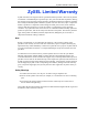
ZyAIR G-2000 Plus User’s Guide Customer Support Please have the following information ready when you contact customer support. • • • • method Product model and serial number. Warranty Information. Date that you received your device. Brief description of the problem and the steps you took to solve it. Support e-mail Telephonea Web Site Sales e-mail Fax FTP Site Regular Mail location Corporate support@zyxel.com.tw +886-3-578-3942 HeadQuarters (Worldwide) sales@zyxel.com.tw +886-3-578-2439 www.
ZyAIR G-2000 Plus User’s Guide SPAIN Sweden United Kingdom support@zyxel.es +34 902 195 420 www.zyxel.es ZyXEL Communications Alejandro Villegas 33 1º, 28043 Madrid Spain sales@zyxel.es +34 913 005 345 support@zyxel.se +46 31 744 7700 www.zyxel.se ZyXEL Communications A/S Sjöporten 4, 41764 Göteborg Sweden sales@zyxel.se +46 31 744 7701 technical@zyxel.co.uk +44 (0) 8702 909090 www.zyxel.co.uk +44 (0) 8702 909091 ftp.zyxel.co.uk ZyXEL Communications UK Ltd.
ZyAIR G-2000 Plus User’s Guide 7 Customer Support
ZyAIR G-2000 Plus User’s Guide Table of Contents Copyright .................................................................................................................. 2 Federal Communications Commission (FCC) Interference Statement ............... 3 ZyXEL Limited Warranty.......................................................................................... 4 Customer Support.................................................................................................... 5 Preface ...........
ZyAIR G-2000 Plus User’s Guide 1.2.2.16 PPPoE Support (RFC2516) ..........................................................40 1.2.2.17 PPTP Encapsulation .....................................................................40 1.2.2.18 Network Address Translation (NAT) ..............................................40 1.2.2.19 Traffic Redirect ..............................................................................40 1.2.2.20 NAT for Single-IP-address Internet Access ...................................
ZyAIR G-2000 Plus User’s Guide 3.6.1 WAN IP Address Assignment ...................................................................58 3.6.2 IP Address and Subnet Mask ...................................................................59 3.6.3 DNS Server Address Assignment .............................................................59 3.6.4 WAN MAC Address ..................................................................................59 3.7 Basic Setup Complete ............................................
ZyAIR G-2000 Plus User’s Guide Chapter 7 Wireless Security ................................................................................................... 88 7.1 Wireless Security Overview ...............................................................................88 7.2 Security Parameters Summary ..........................................................................90 7.3 WEP Overview ...................................................................................................90 7.3.
ZyAIR G-2000 Plus User’s Guide 9.2.1 Ethernet Encapsulation ...........................................................................124 9.2.1.1 Service Type .................................................................................125 9.2.2 PPPoE Encapsulation .............................................................................126 9.2.3 PPTP Encapsulation ...............................................................................129 9.3 TCP/IP Priority (Metric) .......................
ZyAIR G-2000 Plus User’s Guide 12.3 Configuring Telnet ..........................................................................................158 12.4 Configuring TELNET ......................................................................................159 12.5 Configuring FTP .............................................................................................160 12.6 SNMP .............................................................................................................161 12.6.
ZyAIR G-2000 Plus User’s Guide 14.5.4 UDP/ICMP Security ..............................................................................187 14.5.5 Upper Layer Protocols ..........................................................................188 14.6 Guidelines For Enhancing Security With Your Firewall ..................................188 14.7 Packet Filtering Vs Firewall ............................................................................188 14.7.1 Packet Filtering: ................................
ZyAIR G-2000 Plus User’s Guide 17.2 Self-signed Certificates ..................................................................................215 17.3 Configuration Summary .................................................................................215 17.4 My Certificates ...............................................................................................215 17.5 Certificate File Formats ..................................................................................218 17.
ZyAIR G-2000 Plus User’s Guide Chapter 21 General Setup ....................................................................................................... 258 21.1 General Setup ................................................................................................258 21.1.1 Procedure To Configure Menu 1 ...........................................................258 21.1.2 Procedure to Configure Dynamic DNS .................................................260 Chapter 22 Menu 2 WAN Setup ....
ZyAIR G-2000 Plus User’s Guide Chapter 26 Static Route Setup ............................................................................................... 290 26.1 IP Static Route Setup .....................................................................................290 Chapter 27 Dial-in User Setup ................................................................................................ 292 27.1 Dial-in User Setup ..............................................................................
ZyAIR G-2000 Plus User’s Guide 30.2 Access Methods .............................................................................................326 30.3 Enabling the Firewall ......................................................................................326 Chapter 31 SNMP Configuration ............................................................................................ 328 31.1 About SNMP ..................................................................................................
ZyAIR G-2000 Plus User’s Guide 34.2.5 Backup Configuration Using TFTP .......................................................354 34.2.6 Example: TFTP Command ...................................................................354 34.2.7 GUI-based TFTP Clients ......................................................................355 34.3 Restore Configuration ...................................................................................355 34.3.1 Restore Using FTP ........................................
ZyAIR G-2000 Plus User’s Guide Appendix D IP Address Assignment Conflicts ...................................................................... 392 Appendix E IP Subnetting ........................................................................................................ 396 Appendix F Command Interpreter........................................................................................... 404 Appendix G Log Descriptions...........................................................................
ZyAIR G-2000 Plus User’s Guide 21 Table of Contents
ZyAIR G-2000 Plus User’s Guide List of Figures Figure 1 Internet Access Application Example .................................................................... 42 Figure 2 Change Password Screen .................................................................................... 45 Figure 3 Replace Certificate Screen ................................................................................... 45 Figure 4 The MAIN MENU Screen of the Web Configurator ...............................................
ZyAIR G-2000 Plus User’s Guide Figure 37 Wireless: WPA .................................................................................................... 103 Figure 38 Wireless: 802.1x and Dynamic WEP .................................................................. 106 Figure 39 Wireless: 802.1x and Static WEP ....................................................................... 108 Figure 40 Wireless: 802.1x .............................................................................................
ZyAIR G-2000 Plus User’s Guide Figure 80 WAN to LAN Traffic ............................................................................................. 196 Figure 81 Default Rule ....................................................................................................... 197 Figure 82 Rule Summary .................................................................................................... 198 Figure 83 Creating/Editing A Firewall Rule ....................................................
ZyAIR G-2000 Plus User’s Guide Figure 123 Menu 1.1 Configure Dynamic DNS .................................................................. 260 Figure 124 Menu 2 WAN Setup .......................................................................................... 262 Figure 125 Menu 3 LAN Setup ........................................................................................... 264 Figure 126 Menu 3.1 LAN Port Filter Setup. .......................................................................
ZyAIR G-2000 Plus User’s Guide Figure 166 Example 4: Menu 15.1.1 Address Mapping Rules ............................................ 310 Figure 167 Menu 15.3 Trigger Port Setup ........................................................................... 311 Figure 168 Outgoing Packet Filtering Process .................................................................... 312 Figure 169 Filter Rule Process ............................................................................................
ZyAIR G-2000 Plus User’s Guide Figure 209 Budget Management ......................................................................................... 364 Figure 210 Menu 24.9.2 - Call History ................................................................................ 365 Figure 211 Menu 24.10 System Maintenance : Time and Date Setting .............................. 366 Figure 212 Menu 24.11 – Remote Management Control ....................................................
ZyAIR G-2000 Plus User’s Guide List of Tables Table 1 IEEE 802.11b ......................................................................................................... 37 Table 2 IEEE 802.11g ......................................................................................................... 38 Table 3 Wizard 1 : General Setup ...................................................................................... 50 Table 4 Wizard 2 : Wireless LAN Setup ...........................................
ZyAIR G-2000 Plus User’s Guide Table 37 Ethernet Encapsulation ....................................................................................... 126 Table 38 PPPoE Encapsulation ......................................................................................... 128 Table 39 PPTP Encapsulation ............................................................................................ 130 Table 40 WAN: IP ............................................................................................
ZyAIR G-2000 Plus User’s Guide Table 80 Firmware Upload ................................................................................................. 245 Table 81 Restore Configuration .......................................................................................... 248 Table 82 Main Menu Commands ....................................................................................... 254 Table 83 Main Menu Summary .................................................................................
ZyAIR G-2000 Plus User’s Guide Table 123 Call History Fields .............................................................................................. 365 Table 124 System Maintenance : Time and Date Setting .................................................. 366 Table 125 Menu 24.11 – Remote Management Control ..................................................... 369 Table 126 Menu 26.1 Schedule Set Setup .........................................................................
ZyAIR G-2000 Plus User’s Guide Preface Congratulations on your purchase of the ZyAIR G-2000 Plus - 802.11g Wireless 4 port Router. A wireless router is an access point and router rolled into one. It is a cost-effect solution to share Internet access with multiple computers and expand your wired network. Your ZyAIR is easy to install and configure. Note: Register your product online to receive e-mail notices of firmware upgrades and information at www.zyxel.com for global products, or at www.us.zyxel.
ZyAIR G-2000 Plus User’s Guide User Guide Feedback Help us help you! E-mail all User Guide-related comments, questions or suggestions for improvement to techwriters@zyxel.com.tw or send regular mail to The Technical Writing Team, ZyXEL Communications Corp., 6 Innovation Road II, Science-Based Industrial Park, Hsinchu, 300, Taiwan. Thank you! Syntax Conventions • “Enter” means for you to type one or more characters. “Select” or “Choose” means for you to use one predefined choices.
ZyAIR G-2000 Plus User’s Guide Graphics Icons Key ZyAIR Computer Notebook computer Server DSLAM Firewall Modem Switch Router Wireless Signal Preface 34
ZyAIR G-2000 Plus User’s Guide 35 Preface
ZyAIR G-2000 Plus User’s Guide CHAPTER 1 Getting to Know Your ZyAIR This chapter introduces the main features and applications of the ZyAIR. 1.1 Introducing the ZyAIR The ZyAIR G-2000 Plus, an IEEE802.11g compliant broadband wireless sharing gateway, provides wireless connectivity. As an Internet gateway, your ZyAIR can share an Internet connection (through a cable or xDSL modem) with multiple computers using SUA/NAT and DHCP.
ZyAIR G-2000 Plus User’s Guide 1.2.1.4 10/100 Mbps Ethernet WAN The 10/100 Mbps Ethernet WAN port attaches to the Internet via broadband modem or router. 1.2.1.5 Reset Button The ZyAIR reset button is built into the side panel. Use this button to restore the factory default password to 1234; IP address to 192.168.1.1, subnet mask to 255.255.255.0 and DHCP server enabled with a pool of 32 IP addresses starting at 192.168.1.33. . 1.2.1.
ZyAIR G-2000 Plus User’s Guide 1.2.2.4 802.11g Wireless LAN Standard The ZyAIR, complies with the 802.11g wireless standard and is also fully compatible with the 802.11b standard. This means an 802.11b radio card can interface directly with an 802.11g device (and vice versa) at 11 Mbps or lower depending on range. 802.11g has several intermediate rate steps between the maximum and minimum data rates. The 802.11g data rate and modulation are as follows:. Table 2 IEEE 802.
ZyAIR G-2000 Plus User’s Guide 1.2.2.9 Firewall The ZyAIR employs a stateful inspection firewall with DoS (Denial of Service) protection. By default, when the firewall is activated, all incoming traffic from the WAN to the LAN is blocked unless it is initiated from the LAN. The ZyAIR firewall supports TCP/UDP inspection, DoS detection and prevention, real time alerts, reports and logs. 1.2.2.
ZyAIR G-2000 Plus User’s Guide 1.2.2.16 PPPoE Support (RFC2516) PPPoE (Point-to-Point Protocol over Ethernet) emulates a dial-up connection. It allows your ISP to use their existing network configuration with newer broadband technologies such as ADSL. The PPPoE driver on the ZyAIR is transparent to the computers on the LAN, which see only Ethernet and are not aware of PPPoE thus saving you from having to manage PPPoE clients on individual computers. 1.2.2.
ZyAIR G-2000 Plus User’s Guide 1.2.2.22 Multicast Traditionally, IP packets are transmitted in two ways - unicast or broadcast. Multicast is a third way to deliver IP packets to a group of hosts. IGMP (Internet Group Management Protocol) is the protocol used to support multicast groups. The latest version is version 2 (see RFC 2236). The ZyAIR supports versions 1 and 2. 1.2.2.23 IP Alias IP Alias allows you to partition a physical network into logical networks over the same Ethernet interface.
ZyAIR G-2000 Plus User’s Guide 1.2.2.29 Embedded FTP and TFTP Servers The ZyAIR’s embedded FTP and TFTP servers enable fast firmware upgrades as well as configuration file backups and restoration. 1.2.2.30 Wireless Association List With the wireless association list, you can see the list of the wireless stations that are currently using the ZyAIR to access your wired network. 1.2.2.
ZyAIR G-2000 Plus User’s Guide 43 Chapter 1 Getting to Know Your ZyAIR
ZyAIR G-2000 Plus User’s Guide CHAPTER 2 Introducing the Web Configurator This chapter describes how to access the ZyAIR web configurator and provides an overview of its screens. The default IP address of the ZyAIR is 192.168.1.1. 2.1 Web Configurator Overview The embedded web configurator (ewc) allows you to manage the ZyAIR from anywhere through a browser such as Microsoft Internet Explorer or Netscape Navigator. Use Internet Explorer 6.0 and later or Netscape Navigator 7.
ZyAIR G-2000 Plus User’s Guide Figure 2 Change Password Screen 6 Click Apply in the Replace Certificate screen to create a certificate using your ZyAIR’s MAC address that will be specific to this device. Figure 3 Replace Certificate Screen You should now see the MAIN MENU screen.. Note: The management session automatically times out when the time period set in the Administrator Inactivity Timer field expires (default five minutes). Simply log back into the ZyAIR if this happens to you.
ZyAIR G-2000 Plus User’s Guide 2.3 Resetting the ZyAIR If you forget your password or cannot access the web configurator, you will need to reload the factory-default configuration file or use the RESET button on the side panel of the ZyAIR. Uploading this configuration file replaces the current configuration file with the factorydefault configuration file.
ZyAIR G-2000 Plus User’s Guide Figure 4 The MAIN MENU Screen of the Web Configurator Use submenus to configure ZyAIR features. Click WIZARD SETUP for initial configuration including general setup, wireless LAN setup, ISP Parameters for Internet Access and WAN IP/DNS/MAC Address Assignment.
ZyAIR G-2000 Plus User’s Guide CHAPTER 3 Wizard Setup The web configurator’s setup wizard helps you configure your ZyAIR for Internet access and set up wireless LAN. 3.1 Wizard Setup Overview The web configurator’s setup wizard helps you configure your device to access the Internet. The second screen has three variations depending on what encapsulation type you use. Refer to your ISP checklist in the Quick Start Guide to know what to enter in each field.
ZyAIR G-2000 Plus User’s Guide 3.1.4 WPA-PSK Wi-Fi Protected Access (WPA) is a subset of the IEEE 802.11i security specification draft. Key differences between WPA and WEP are user authentication and improved data encryption.The encryption mechanisms used for WPA and WPA-PSK are the same. The only difference between the two is that WPA-PSK uses a simple common password, instead of user-specific credentials.
ZyAIR G-2000 Plus User’s Guide Figure 5 Wizard 1 : General Setup The following table describes the labels in this screen. Table 3 Wizard 1 : General Setup LABEL DESCRIPTION System Name It is recommended you type your computer's "Computer name". In Windows 95/98 click Start, Settings, Control Panel, Network. Click the Identification tab, note the entry for the Computer Name field and enter it as the System Name. In Windows 2000, click Start, Settings, Control Panel and then double-click System.
ZyAIR G-2000 Plus User’s Guide Figure 6 Wizard 2 : Wireless LAN Setup The following table describes the labels in this screen. Table 4 Wizard 2 : Wireless LAN Setup LABEL DESCRIPTION Wireless LAN Setup ESSID Enter a descriptive name (up to 32 printable 7-bit ASCII characters) for the wireless LAN. If you change this field on the ZyAIR, make sure all wireless stations use the same SSID in order to access the network.
ZyAIR G-2000 Plus User’s Guide Figure 7 Wizard 3: Wireless LAN Setup: Basic Security The following table describes the labels in this screen. Table 5 Wizard 3: Wireless LAN Setup: Basic Security LABEL DESCRIPTION Passphrase You can generate or manually enter a WEP key by either: Entering a Passphrase (up to 32 printable characters) and clicking Generate. The Prestige automatically generates a WEP key. Or Entering a manual key in a Key field and selecting ASCII or Hex WEP key input method.
ZyAIR G-2000 Plus User’s Guide Figure 8 Wizard 3: Wireless LAN Setup: Extend Security The following table describes the labels in this screen. Table 6 Wizard 3: Wireless LAN Setup: Extend Security LABEL DESCRIPTION Pre-Shared Key Type from 8 to 63 case-sensitive ASCII characters. You can set up the most secure wireless connection by configuring WPA in the advanced wireless screen. You need to configure an authentication server to do this. Back Click Back to display the previous screen.
ZyAIR G-2000 Plus User’s Guide Figure 9 Wizard 4: Ethernet Encapsulation The following table describes the labels in this screen. Table 7 Wizard 4: Ethernet Encapsulation LABEL DESCRIPTION ISP Parameters for Internet Access Encapsulation You must choose the Ethernet option when the WAN port is used as a regular Ethernet. Otherwise, choose PPP over Ethernet or PPTP for a dial-up connection.
ZyAIR G-2000 Plus User’s Guide 3.5.2 PPPoE Encapsulation Point-to-Point Protocol over Ethernet (PPPoE) functions as a dial-up connection. PPPoE is an IETF (Internet Engineering Task Force) draft standard specifying how a host personal computer interacts with a broadband modem (for example DSL, cable, wireless, etc.) to achieve access to high-speed data networks. For the service provider, PPPoE offers an access and authentication method that works with existing access control systems (for instance, Radius).
ZyAIR G-2000 Plus User’s Guide Figure 10 Wizard 4: PPPoE Encapsulation The following table describes the labels in this screen. Table 8 Wizard 4: PPPoE Encapsulation LABEL DESCRIPTION ISP Parameter for Internet Access Encapsulation Choose PPP over Ethernet from the pull-down list box. PPPoE forms a dial-up connection. Service Name Type the name of your service provider. User Name Type the user name given to you by your ISP. Password Type the password associated with the user name above.
ZyAIR G-2000 Plus User’s Guide PPTP supports on-demand, multi-protocol, and virtual private networking over public networks, such as the Internet. Refer to the appendix for more information on PPTP. Note: The ZyAIR supports one PPTP server connection at any given time.
ZyAIR G-2000 Plus User’s Guide Table 9 Wizard 4: PPTP Encapsulation LABEL DESCRIPTION My IP Address Type the (static) IP address assigned to you by your ISP. My IP Subnet Mask Type the subnet mask assigned to you by your ISP (if given). Server IP Address Type the IP address of the PPTP server. Connection ID/ Name Enter the connection ID or connection name in this field. It must follow the "c:id" and "n:name" format. For example, C:12 or N:My ISP.
ZyAIR G-2000 Plus User’s Guide 3.6.2 IP Address and Subnet Mask Similar to the way houses on a street share a common street name, so too do computers on a LAN share one common network number. Where you obtain your network number depends on your particular situation. If the ISP or your network administrator assigns you a block of registered IP addresses, follow their instructions in selecting the IP addresses and the subnet mask.
ZyAIR G-2000 Plus User’s Guide You can configure the WAN port's MAC address by either using the factory default or cloning the MAC address from a computer on your LAN. Once it is successfully configured, the address will be copied to the "rom" file (ZyNOS configuration file). It will not change unless you change the setting or upload a different "rom" file. Note: ZyXEL recommends you clone the MAC address from a computer on your LAN even if your ISP does not require MAC address authentication.
ZyAIR G-2000 Plus User’s Guide Figure 12 Wizard 5: WAN Setup The following table describes the labels in this screen Table 12 Wizard 5: WAN Setup LABEL DESCRIPTION WAN IP Address Assignment Get automatically from ISP Select this option If your ISP did not assign you a fixed IP address. This is the default selection. Use fixed IP address Select this option If the ISP assigned a fixed IP address. Enter a subnet mask appropriate to your network and the gateway IP address if applicable.
ZyAIR G-2000 Plus User’s Guide Table 12 Wizard 5: WAN Setup LABEL DESCRIPTION First DNS Server Select From ISP if your ISP dynamically assigns DNS server information (and the ZyAIR's WAN IP address). The field to the right displays the (readonly) DNS server IP address that the ISP assigns. Select User-Defined if you have the IP address of a DNS server. Enter the DNS server's IP address in the field to the right. Select None if you do not want to configure DNS servers.
ZyAIR G-2000 Plus User’s Guide Figure 13 Wizard Finish Well done! You have successfully set up the ZyAIR. A congratulations screen displays some information.
ZyAIR G-2000 Plus User’s Guide CHAPTER 4 System Screens 4.1 System Overview This section provides information on general system setup. 4.2 Configuring General Setup Click the SYSTEM link under ADVANCED to open the General screen. Figure 14 System General Setup The following table describes the labels in this screen. Table 13 System General Setup LABEL DESCRIPTION General Setup System Name Type a descriptive name to identify the ZyAIR in the Ethernet network.
ZyAIR G-2000 Plus User’s Guide Table 13 System General Setup LABEL DESCRIPTION Administrator Inactivity Timer Type how many minutes a management session (either via the web configurator or SMT) can be left idle before the session times out. The default is 5 minutes. After it times out you have to log in with your password again. Very long idle timeouts may have security risks. A value of "0" means a management session never times out, no matter how long it has been left idle (not recommended).
ZyAIR G-2000 Plus User’s Guide 4.4 Configuring Dynamic DNS To change your ZyAIR’s DDNS, click SYSTEM, then the DDNS tab. The screen appears as shown. Figure 15 DDNS The following table describes the labels in this screen. Table 14 DDNS LABEL DESCRIPTION Enable DDNS Select this check box to use dynamic DNS. Service Provider Select the name of your Dynamic DNS service provider. DDNS Type Select the type of service that you are registered for from your Dynamic DNS service provider.
ZyAIR G-2000 Plus User’s Guide Table 14 DDNS LABEL DESCRIPTION Use WAN IP address Select this option to update the IP address of the host name(s) automatically by the DDNS server. It is recommended that you select this option. DDNS server auto detect IP Address Select this option to update the IP address of the host name(s) automatically by the DDNS server. It is recommended that you select this option.
ZyAIR G-2000 Plus User’s Guide 4.6 Configuring Time Setting To change your ZyAIR’s time and date, click the SYSTEM link under ADVANCED and then the Time Setting tab. The screen appears as shown. Use this screen to configure the ZyAIR’s time based on your local time zone. Figure 17 Time Setting The following table describes the labels in this screen. Table 16 Time Setting LABEL DESCRIPTION Time Protocol Select the time service protocol that your time server sends when you turn on the ZyAIR.
ZyAIR G-2000 Plus User’s Guide Table 16 Time Setting 69 LABEL DESCRIPTION New Time (hh:mm:ss) This field displays the last updated time from the time server. When you select None in the Time Protocol field, enter the new time in this field and then click Apply. Current Date (yyyy/ mm/dd) This field displays the date of your ZyAIR. Each time you reload this page, the ZyAIR synchronizes the date with the time server.
ZyAIR G-2000 Plus User’s Guide CHAPTER 5 LAN Screens This chapter describes how to configure LAN settings. 5.1 LAN Overview Local Area Network (LAN) is a shared communication system to which many computers are attached. The LAN screens can help you configure a LAN DHCP server, manage IP addresses, and partition your physical network into logical networks. 5.
ZyAIR G-2000 Plus User’s Guide • IP address of 192.168.1.1 with subnet mask of 255.255.255.0 (24 bits) • DHCP server enabled with 32 client IP addresses starting from 192.168.1.33. These parameters should work for the majority of installations. If your ISP gives you explicit DNS server address(es), read the embedded web configurator help regarding what fields need to be configured. 5.3.
ZyAIR G-2000 Plus User’s Guide 224.0.0.0 is not assigned to any group and is used by IP multicast computers. The address 224.0.0.1 is used for query messages and is assigned to the permanent group of all IP hosts (including gateways). All hosts must join the 224.0.0.1 group in order to participate in IGMP. The address 224.0.0.2 is assigned to the multicast routers group. The ZyAIR supports both IGMP version 1 (IGMP-v1) and IGMP version 2 (IGMP-v2).
ZyAIR G-2000 Plus User’s Guide Figure 18 LAN IP The following table describes the labels in this screen. Table 17 LAN IP LABEL DESCRIPTION DHCP Server DHCP (Dynamic Host Configuration Protocol, RFC 2131 and RFC 2132) allows individual clients (computers) to obtain TCP/IP configuration at startup from a server. Leave the DHCP Server check box selected unless your ISP instructs you to do otherwise. Clear it to disable the ZyAIR acting as a DHCP server.
ZyAIR G-2000 Plus User’s Guide Table 17 LAN IP LABEL DESCRIPTION First DNS Server Select From ISP if your ISP dynamically assigns DNS server information (and Second DNS Server the ZyAIR's WAN IP address). The field to the right displays the (read-only) DNS server IP address that the ISP assigns. Third DNS Server Select User-Defined if you have the IP address of a DNS server. Enter the DNS server's IP address in the field to the right. If you chose User-Defined, but leave the IP address set to 0.0.0.
ZyAIR G-2000 Plus User’s Guide Table 17 LAN IP LABEL DESCRIPTION Allow between LAN and WAN Select this check box to forward NetBIOS packets from the LAN to the WAN and from the WAN to the LAN. If your firewall is enabled with the default policy set to block WAN to LAN traffic, you also need to enable the default WAN to LAN firewall rule that forwards NetBIOS traffic. Clear this check box to block all NetBIOS packets going from the LAN to the WAN and from the WAN to the LAN.
ZyAIR G-2000 Plus User’s Guide Figure 19 Static DHCP The following table describes the labels in this screen. Table 18 Static DHCP LABEL DESCRIPTION # This is the index number of the Static IP table entry (row). MAC Address Type the MAC address (with colons) of a computer on your LAN. IP Address Type the LAN IP address in this field. Apply Click Apply to save your changes back to the ZyAIR. Reset Click Reset to begin configuring this screen afresh. 5.
ZyAIR G-2000 Plus User’s Guide Figure 20 IP Alias The following table describes the labels in this screen. Table 19 IP Alias 77 LABEL DESCRIPTION IP Alias 1,2 Select the check box to configure another LAN network for the ZyAIR. IP Address Enter the IP address of your ZyAIR in dotted decimal notation. IP Subnet Mask Your ZyAIR will automatically calculate the subnet mask based on the IP address that you assign. Unless you are implementing subnetting, use the subnet mask computed by the ZyAIR.
ZyAIR G-2000 Plus User’s Guide CHAPTER 6 Wireless Configuration and Roaming This chapter discusses how to configure the Wireless and Roaming screens on the ZyAIR. 6.1 Wireless LAN Overview This section introduces the wireless LAN(WLAN) and some basic scenarios. 6.1.1 IBSS An Independent Basic Service Set (IBSS), also called an Ad-hoc network, is the simplest WLAN configuration.
ZyAIR G-2000 Plus User’s Guide Intra-BSS traffic is traffic between wireless stations in the BSS. When Intra-BSS is enabled, wireless station A and B can access the wired network and communicate with each other. When Intra-BSS is disabled, wireless station A and B can still access the wired network but cannot communicate with each other. Figure 22 Basic Service set 6.1.
ZyAIR G-2000 Plus User’s Guide Figure 23 Extended Service Set 6.2 Wireless LAN Basics Refer also to the Wizard Setup chapter for more background information on Wireless LAN features, such as channels. 6.2.1 RTS/CTS A hidden node occurs when two stations are within range of the same access point, but are not within range of each other. The following figure illustrates a hidden node.
ZyAIR G-2000 Plus User’s Guide Figure 24 RTS/CTS When station A sends data to the ZyAIR, it might not know that station B is already using the channel. If these two stations send data at the same time, collisions may occur when both sets of data arrive at the AP at the same time, resulting in a loss of messages for both stations. RTS/CTS is designed to prevent collisions due to hidden nodes.
ZyAIR G-2000 Plus User’s Guide A large Fragmentation Threshold is recommended for networks not prone to interference while you should set a smaller threshold for busy networks or networks that are prone to interference. If the Fragmentation Threshold value is smaller than the RTS/CTS value (see previously) you set, then the RTS (Request To Send)/CTS (Clear to Send) handshake will never occur as data frames will be fragmented before they reach RTS/CTS size. 6.
ZyAIR G-2000 Plus User’s Guide Figure 25 Wireless The following table describes the general wireless LAN labels in this screen. Table 20 Wireless LABEL DESCRIPTION Enable Wireless LAN Click the check box to activate wireless LAN. ESSID (Extended Service Set IDentity) The ESSID identifies the Service Set with which a wireless station is associated. Wireless stations associating to the access point (AP) must have the same ESSID.
ZyAIR G-2000 Plus User’s Guide See the Wireless Security chapter for information on the other labels in this screen. 6.4 Configuring Roaming A wireless station is a device with an IEEE 802.11mode compliant wireless adapter. An access point (AP) acts as a bridge between the wireless and wired networks. An AP creates its own wireless coverage area. A wireless station can associate with a particular access point only if it is within the access point’s coverage area.
ZyAIR G-2000 Plus User’s Guide 1 As wireless station Y moves from the coverage area of access point P1 to that of access point 2 P2, it scans and uses the signal of access point P2. 3 Access point P2 acknowledges the presence of wireless station Y and relays this information to access point P1 through the wired LAN. 4 Access point P1 updates the new position of wireless station. 5 Wireless station Y sends a request to access point P2 for re-authentication. 6.4.
ZyAIR G-2000 Plus User’s Guide Figure 27 Roaming The following table describes the labels in this screen. Table 21 Roaming LABEL DESCRIPTION Active Select Yes from the drop-down list box to enable roaming on the ZyAIR if you have two or more ZyAIRs on the same subnet. Note: All APs on the same subnet and the wireless stations must have the same ESSID to allow roaming. Port Enter the port number to communicate roaming information between APs. The port number must be the same on all APs.
ZyAIR G-2000 Plus User’s Guide 87 Chapter 6 Wireless Configuration and Roaming
ZyAIR G-2000 Plus User’s Guide CHAPTER 7 Wireless Security This Chapter describes how to use the MAC Filter, 802.1x, Roaming and RADIUS to configure wireless security on your ZyAIR. 7.1 Wireless Security Overview Wireless security is vital to your network to protect wireless communication between wireless stations, access points and the wired network. The figure below shows the possible wireless security levels on your ZyAIR.
ZyAIR G-2000 Plus User’s Guide Figure 29 Wireless: No Security The following table describes the labels in this screen. Table 22 Wireless No Security 89 LABEL DESCRIPTION Security Choose from one of the security features listed in the drop-down box. • No Security • Static WEP • WPA-PSK • WPA • 802.1x + Dynamic WEP • 802.1x + Static WEP • 802.1x + No WEP Enable Breathing LED Select this check box to enable the Breathing LED, also known as the ZyAIR LED.
ZyAIR G-2000 Plus User’s Guide 7.2 Security Parameters Summary Refer to this table to see what other security parameters you should configure for each Authentication Method/ key management protocol type. You enter manual keys by first selecting 64-bit WEP or 128-bit WEP from the WEP Encryption field and then typing the keys (in ASCII or hexadecimal format) in the key text boxes. MAC address filters are not dependent on how you configure these security features.
ZyAIR G-2000 Plus User’s Guide Figure 30 WEP Authentication Steps Open system authentication involves an unencrypted two-message procedure. A wireless station sends an open system authentication request to the AP, which will then automatically accept and connect the wireless station to the network. In effect, open system is not authentication at all as any station can gain access to the network. Shared key authentication involves a four-message procedure.
ZyAIR G-2000 Plus User’s Guide Figure 31 Wireless: Static WEP Encryption The following table describes the wireless LAN security labels in this screen. Table 24 Wireless: Static WEP Encryption LABEL DESCRIPTION Passphrase Enter a Passphrase (up to 32 printable characters) and click Generate. The ZyAIR automatically generates a WEP key. WEP Encryption Select 64-bit WEP or 128-bit WEP to enable data encryption.
ZyAIR G-2000 Plus User’s Guide Table 24 Wireless: Static WEP Encryption LABEL DESCRIPTION Key 1 to Key 4 The WEP keys are used to encrypt data. Both the ZyAIR and the wireless stations must use the same WEP key for data transmission. If you chose 64-bit WEP, then enter any 5 ASCII characters or 10 hexadecimal characters ("0-9", "A-F"). If you chose 128-bit WEP, then enter 13 ASCII characters or 26 hexadecimal characters ("0-9", "A-F").
ZyAIR G-2000 Plus User’s Guide 7.5.2 Encryption WPA improves data encryption by using Temporal Key Integrity Protocol (TKIP), Message Integrity Check (MIC) and IEEE 802.1x. Temporal Key Integrity Protocol (TKIP) uses 128-bit keys that are dynamically generated and distributed by the authentication server. It includes a per-packet key mixing function, a Message Integrity Check (MIC) named Michael, an extended initialization vector (IV) with sequencing rules, and a re-keying mechanism.
ZyAIR G-2000 Plus User’s Guide Figure 32 WPA - PSK Authentication 7.6 Configuring WPA-PSK Authentication In order to configure and enable WPA-PSK Authentication; click the WIRELESS link under ADVANCED to display the Wireless screen. Select WPA-PSK from the Security list.
ZyAIR G-2000 Plus User’s Guide Figure 33 Wireless: WPA-PSK The following table describes the labels in this screen. Table 25 Wireless: WPA-PSK LABEL DESCRIPTION Pre-Shared Key The encryption mechanisms used for WPA and WPA-PSK are the same. The only difference between the two is that WPA-PSK uses a simple common password, instead of user-specific credentials. Type a pre-shared key from 8 to 63 case-sensitive ASCII characters (including spaces and symbols).
ZyAIR G-2000 Plus User’s Guide Table 25 Wireless: WPA-PSK LABEL DESCRIPTION Enable Breathing LED Select this check box to enable the Breathing LED, also known as the ZyAIR LED. The blue ZyAIR LED is on when the ZyAIR is on and blinks (or breaths) when data is being transmitted to/from its wireless stations. Clear the check box to turn this LED off even when the ZyAIR is on and data is being transmitted/received. Preamble Select a preamble type from the drop-down list menu.
ZyAIR G-2000 Plus User’s Guide Figure 34 WPA with RADIUS Application Example 7.8 Configuring WPA Authentication In order to configure and enable WPA Authentication; click the WIRELESS link under ADVANCED to display the Wireless screen. Select WPA from the Security list.
ZyAIR G-2000 Plus User’s Guide Figure 35 Wireless: WPA The following table describes the labels in this screen. Table 26 Wireless: WPA LABEL DESCRIPTION ReAuthentication Timer (in seconds) Specify how often wireless stations have to reenter usernames and passwords in order to stay connected. Enter a time interval between 10 and 9999 seconds. The default time interval is 1800 seconds (30 minutes).
ZyAIR G-2000 Plus User’s Guide Table 26 Wireless: WPA LABEL DESCRIPTION WPA Group Key Update Timer The WPA Group Key Update Timer is the rate at which the AP (if using WPAPSK key management) or RADIUS server (if using WPA key management) sends a new group key out to all clients. The re-keying process is the WPA equivalent of automatically changing the WEP key for an AP and all stations in a WLAN on a periodic basis. Setting of the WPA Group Key Update Timer is also supported in WPA-PSK mode.
ZyAIR G-2000 Plus User’s Guide The following types of RADIUS messages are exchanged between the access point and the RADIUS server for user accounting: 7.9.1.2 Accounting-Request Sent by the access point requesting accounting. 7.9.1.3 Accounting-Response Sent by the RADIUS server to indicate that it has started or stopped accounting. In order to ensure network security, the access point and the RADIUS server use a shared secret key, which is a password, they both know.
ZyAIR G-2000 Plus User’s Guide 4 The RADIUS server checks the user information against its user profile database and determines whether or not to authenticate the wireless station. 7.10 Configuring RADIUS You can configure the ZyAIR to authenticate wireless clients using an external RADIUS server or have the ZyAIR itself act as a RADIUS server using the internal RADIUS server.
ZyAIR G-2000 Plus User’s Guide Figure 37 Wireless: WPA The following table describes the labels in this screen. Table 27 RADIUS LABEL DESCRIPTION Internal RADIUS Server Select this radio button to use the ZyAIR’s Internal RADIUS Server. You can authenticate other AP’s or wireless clients in other wireless networks. External RADIUS Server Select the radio button to use an External RADIUS Server to authenticate the ZyAIR’s wireless clients.
ZyAIR G-2000 Plus User’s Guide Table 27 RADIUS LABEL DESCRIPTION Shared Secret Enter a password (up to 31 alphanumeric characters) as the key to be shared between the external authentication server and the ZyAIR. The key must be the same on the external authentication server and your ZyAIR. The key is not sent over the network. Accounting Server Active Select the check box to enable user accounting through an external authentication server.
ZyAIR G-2000 Plus User’s Guide • EAP-TLS • EAP-TTLS • PEAP Note: EAP-MD5 cannot be used with Dynamic WEP Key Exchange 7.13 Configuring 802.1x and Dynamic WEP Key Exchange In order to configure and enable 802.1x and Dynamic WEP Key Exchange; click the WIRELESS link under ADVANCED to display the Wireless screen. Select 802.1x + Dynamic WEP from the Security list.
ZyAIR G-2000 Plus User’s Guide Figure 38 Wireless: 802.1x and Dynamic WEP The following table describes the labels in this screen. Table 28 Wireless: 802.1x and Dynamic WEP LABEL DESCRIPTION ReAuthentication Timer (in seconds) Specify how often wireless stations have to reenter usernames and passwords in order to stay connected. Enter a time interval between 10 and 9999 seconds. The default time interval is 1800 seconds (30 minutes).
ZyAIR G-2000 Plus User’s Guide Table 28 Wireless: 802.1x and Dynamic WEP LABEL DESCRIPTION Apply Click Apply to save your changes back to the ZyAIR. Reset Click Reset to reload the previous configuration for this screen. 7.14 Configuring 802.1x and Static WEP Key Exchange In order to configure and enable 802.1x and Static WEP Key Exchange; click the WIRELESS link under ADVANCED to display the Wireless screen. Select 802.1x + Static WEP from the Security list.
ZyAIR G-2000 Plus User’s Guide Figure 39 Wireless: 802.1x and Static WEP The following table describes the labels in this screen. Table 29 Wireless: 802.1x and Static WEP LABEL DESCRIPTION Passphrase Enter a Passphrase (up to 32 printable characters) and click Generate. The ZyAIR automatically generates a WEP key. WEP Encryption Select 64-bit WEP or 128-bit WEP to enable data encryption.
ZyAIR G-2000 Plus User’s Guide Table 29 Wireless: 802.1x and Static WEP LABEL DESCRIPTION Authentication Method This field is activated when you select 64-bit WEP or 128-bit WEP in the WEP Encryption field. Select Auto, Open System or Shared Key from the drop-down list box. ASCII Select this option in order to enter ASCII characters as the WEP keys. Hex Select this option in order to enter hexadecimal characters as the WEP keys.
ZyAIR G-2000 Plus User’s Guide 7.15 Configuring 802.1x In order to configure and enable 802.1x; click the WIRELESS link under ADVANCED to display the Wireless screen. Select 802.1x + No WEP from the Security list.
ZyAIR G-2000 Plus User’s Guide Figure 40 Wireless: 802.1x The following table describes the labels in this screen. Table 30 Wireless: 802.1x and No WEP LABEL DESCRIPTION ReAuthentication Timer (in seconds) Specify how often wireless stations have to reenter usernames and passwords in order to stay connected. Enter a time interval between 10 and 9999 seconds. The default time interval is 1800 seconds (30 minutes).
ZyAIR G-2000 Plus User’s Guide Table 30 Wireless: 802.1x and No WEP LABEL DESCRIPTION Authentication Databases The authentication database contains wireless station login information. The trusted user database is the built-in database on the ZyAIR. The RADIUS is an external server. Use this drop-down list box to select which database the ZyAIR should use (first) to authenticate a wireless station. Before you specify the priority, make sure you have set up the corresponding database correctly first.
ZyAIR G-2000 Plus User’s Guide Figure 41 MAC Address Filter The following table describes the labels in this menu. Table 31 MAC Address Filter LABEL DESCRIPTION Active Select Yes from the drop down list box to enable MAC address filtering. Filter Action Define the filter action for the list of MAC addresses in the MAC Address table.
ZyAIR G-2000 Plus User’s Guide CHAPTER 8 Internal RADIUS Server This chapter describes how to use the internal RADIUS server to authenticate wireless clients or other AP’s in other wireless networks.For more background information on RADIUS, see section 7.9. 8.1 Internal RADIUS Overview The ZyAIR has a built-in RADIUS server that can authenticate wireless clients or other AP’s in other wireless networks. The ZyAIR can function as an AP and as a RADIUS server at the same time.
ZyAIR G-2000 Plus User’s Guide Figure 42 ZyAIR Authenticates Wireless Stations Figure 43 ZyAIR Authenicates other AP’s ZyAIR as a RADIUS server Other AP’s Table 32 Internal RADIUS Server 115 LABEL DESCRIPTION Setting Use the Setting screen to display information about the ZyAIR’s certificate and to activate the internal RADIUS server on your ZyAIR. Trusted AP Use the Trusted AP screen to configure which trusted AP’s you can authenticate.
ZyAIR G-2000 Plus User’s Guide 8.2 Internal RADIUS Server Setting The INTERNAL RADIUS SERVER Setting screen displays information about certificates. The certificates are used by wireless clients to authenticate the RADIUS server. Information matching the certificate is held on the wireless clients utility, for example, Funk Software’s Odyssey client. A password and user name on the utility must match the the Trusted Users list so that the RADIUS server can be authenticated.
ZyAIR G-2000 Plus User’s Guide Figure 44 Internal RADIUS Server Setting Screen The following table describes the labels in this screen. Table 33 My Certificates 117 LABEL DESCRIPTION Active Select the Active checkbox to have the ZyAIR use its internal RADIUS server to authenticate wireless clients or other AP’s. # This field displays the certificate index number. The certificates are listed in alphabetical order. Certificates can be added or removed in the Advanced Certificate screens.
ZyAIR G-2000 Plus User’s Guide Table 33 My Certificates (continued) LABEL DESCRIPTION Issuer This field displays identifying information about the certificate’s issuing certification authority, such as a common name, organizational unit or department, organization or company and country. With self-signed certificates, this is the same information as in the Subject field. Valid From This field displays the date that the certificate becomes applicable.
ZyAIR G-2000 Plus User’s Guide 2 Configure wireless client user names and passwords in the Trusted Users database to use a trusted AP as a relay between the RADIUS server and the wireless clients. The wireless clients can then be authenticated by the RADIUS server. 8.4 Configuring Trusted AP To configure trusted AP’s on the ZyAIR’s internal RADIUS, click the AUTH SERVER link under ADVANCED and then the Trusted AP tab. The screen appears as shown.
ZyAIR G-2000 Plus User’s Guide Table 34 Trusted AP LABEL DESCRIPTION Shared Secret Enter a password (up to 31 alphanumeric characters, no spaces) to be shared between the trusted AP and the ZyAIR. Note: The first trusted AP fields are reserved for the ZyAIR. They are grayed out and therefore cannot be configured. The shared secret must be the same on the trusted AP and your ZyAIR. The shared secret is not sent over the network. The shared secret is used to encrypt messages from and to the ZyAIR.
ZyAIR G-2000 Plus User’s Guide Figure 47 Trusted Users Screen The following table describes the labels in this screen. Table 35 Trusted Users LABEL DESCRIPTION # This field displays the trusted user index number. Active Select this checkbox to have the ZyAIR authenticate wireless clients with the same user name and password activated on thier wireless utility. User Name Enter the username for this user account. This name can be up to 31 alphanumeric characters long, including spaces.
ZyAIR G-2000 Plus User’s Guide Table 35 Trusted Users LABEL DESCRIPTION Apply Click Apply to save your changes back to the ZyAIR. Reset Click Reset to begin configuring this screen afresh.
ZyAIR G-2000 Plus User’s Guide 123 Chapter 8 Internal RADIUS Server
ZyAIR G-2000 Plus User’s Guide CHAPTER 9 WAN This chapter describes how to configure WAN settings. 9.1 WAN Overview A WAN (Wide Area Network) is an outside connection to another network or the Internet. See the Wizard Setup chapter for more background information on most fields in the WAN screens. Background information on WAN fields not included in the Wizard is described here. 9.2 Configuring WAN ISP To change your ZyAIR’s WAN ISP settings, click WAN, then the WAN ISP tab.
ZyAIR G-2000 Plus User’s Guide Figure 48 Ethernet Encapsulation The following table describes the labels in this screen. Table 36 Ethernet Encapsulation LABEL DESCRIPTION Encapsulation You must choose the Ethernet option when the WAN port is used as a regular Ethernet. Service Type Choose from Standard, Telstra (RoadRunner Telstra authentication method), RR-Manager (Roadrunner Manager authentication method), RR-Toshiba (Roadrunner Toshiba authentication method) or Telia Login.
ZyAIR G-2000 Plus User’s Guide Figure 49 Ethernet Encapsulation The following table describes the labels in this screen. Table 37 Ethernet Encapsulation LABEL DESCRIPTION Encapsulation You must choose the Ethernet option when the WAN port is used as a regular Ethernet. Service Type Choose from Standard, Telstra (RoadRunner Telstra authentication method), RR-Manager (Roadrunner Manager authentication method), RR-Toshiba (Roadrunner Toshiba authentication method) or Telia Login.
ZyAIR G-2000 Plus User’s Guide For the service provider, PPPoE offers an access and authentication method that works with existing access control systems (for example Radius). PPPoE provides a login and authentication method that the existing Microsoft Dial-Up Networking software can activate, and therefore requires no new learning or procedures for Windows users. One of the benefits of PPPoE is the ability to let you access one of multiple network services, a function known as dynamic service selection.
ZyAIR G-2000 Plus User’s Guide Figure 50 PPPoE Encapsulation The following table describes the labels in this screen. Table 38 PPPoE Encapsulation LABEL DESCRIPTION ISP Parameters for Internet Access Encapsulation The PPP over Ethernet choice is for a dial-up connection using PPPoE. The ZyAIR supports PPPoE (Point-to-Point Protocol over Ethernet). PPPoE is an IETF Draft standard (RFC 2516) specifying how a personal computer (PC) interacts with a broadband modem (i.e. xDSL, cable, wireless, etc.
ZyAIR G-2000 Plus User’s Guide 9.2.3 PPTP Encapsulation Point-to-Point Tunneling Protocol (PPTP) is a network protocol that enables secure transfer of data from a remote client to a private server, creating a Virtual Private Network (VPN) using TCP/IP-based networks. PPTP supports on-demand, multi-protocol and virtual private networking over public networks, such as the Internet. The screen shown next is for PPTP encapsulation.
ZyAIR G-2000 Plus User’s Guide Figure 51 PPTP Encapsulation The following table describes the labels in this screen. Table 39 PPTP Encapsulation LABEL DESCRIPTION ISP Parameters for Internet Access Encapsulation Point-to-Point Tunneling Protocol (PPTP) is a network protocol that enables secure transfer of data from a remote client to a private server, creating a Virtual Private Network (VPN) using TCP/IP-based networks.
ZyAIR G-2000 Plus User’s Guide Table 39 PPTP Encapsulation LABEL DESCRIPTION PPTP Configuration My IP Address Type the (static) IP address assigned to you by your ISP. My IP Subnet Mask Your ZyAIR will automatically calculate the subnet mask based on the IP address that you assign. Unless you are implementing subnetting, use the subnet mask computed by the ZyAIR. Server IP Address Type the IP address of the PPTP server. Connection ID/Name Type your identification name for the PPTP server.
ZyAIR G-2000 Plus User’s Guide Figure 52 WAN: IP The following table describes the labels in this screen. Table 40 WAN: IP LABEL DESCRIPTION WAN IP Address Assignment Get automatically from Select this option If your ISP did not assign you a fixed IP address. This is the ISP default selection. Use fixed IP address Select this option If the ISP assigned a fixed IP address. My WAN IP Address Enter your WAN IP address in this field if you selected Use Fixed IP Address.
ZyAIR G-2000 Plus User’s Guide Table 40 WAN: IP 133 LABEL DESCRIPTION Network Address Translation Network Address Translation (NAT) allows the translation of an Internet protocol address used within one network (for example a private IP address used in a local network) to a different IP address known within another network (for example a public IP address used on the Internet). Choose None to disable NAT. Choose SUA Only if you have a single public IP address.
ZyAIR G-2000 Plus User’s Guide Table 40 WAN: IP LABEL DESCRIPTION Multicast Choose None (default), IGMP-V1 or IGMP-V2. IGMP (Internet Group Multicast Protocol) is a network-layer protocol used to establish membership in a Multicast group - it is not used to carry user data. IGMP version 2 (RFC 2236) is an improvement over version 1 (RFC 1112) but IGMP version 1 is still in wide use.
ZyAIR G-2000 Plus User’s Guide Otherwise, click Spoof this computer's MAC address - IP Address and enter the IP address of the computer on the LAN whose MAC you are cloning. Once it is successfully configured, the address will be copied to the rom file (ZyNOS configuration file). It will not change unless you change the setting or upload a different ROM file.
ZyAIR G-2000 Plus User’s Guide CHAPTER 10 Single User Account (SUA) / Network Address Translation (NAT) This chapter discusses how to configure SUA/NAT on the ZyAIR. 10.1 NAT Overview NAT (Network Address Translation - NAT, RFC 1631) is the translation of the IP address of a host in a packet. For example, the source address of an outgoing packet, used within one network is changed to a different IP address known within another network. 10.1.
ZyAIR G-2000 Plus User’s Guide Note: NAT never changes the IP address (either local or global) of an outside host. 10.1.2 What NAT Does In the simplest form, NAT changes the source IP address in a packet received from a subscriber (the inside local address) to another (the inside global address) before forwarding the packet to the WAN side.
ZyAIR G-2000 Plus User’s Guide Figure 54 How NAT Works 10.1.4 NAT Application The following figure illustrates a possible NAT application, where three inside LANs (logical LANs using IP Alias) behind the ZyAIR can communicate with three distinct WAN networks. More examples follow at the end of this chapter.
ZyAIR G-2000 Plus User’s Guide Figure 55 NAT Application With IP Alias 10.1.5 NAT Mapping Types NAT supports five types of IP/port mapping. They are: • One to One: In One-to-One mode, the ZyAIR maps one local IP address to one global IP address. • Many to One: In Many-to-One mode, the ZyAIR maps multiple local IP addresses to one global IP address. This is equivalent to SUA (i.e., PAT, port address translation), ZyXEL’s Single User Account feature (the SUA Only option).
ZyAIR G-2000 Plus User’s Guide The following table summarizes these types. Table 42 NAT Mapping Types TYPE IP MAPPING SMT ABBREVIATION One-to-One ILA1ÅÆ IGA1 1-1 Many-to-One (SUA/PAT) ILA1ÅÆ IGA1 ILA2ÅÆ IGA1 … M-1 Many-to-Many Overload ILA1ÅÆ IGA1 ILA2ÅÆ IGA2 ILA3ÅÆ IGA1 ILA4ÅÆ IGA2 … M-M Ov Many One-to-One ILA1ÅÆ IGA1 ILA2ÅÆ IGA2 ILA3ÅÆ IGA3 … M-1-1 Server Server 1 IPÅÆ IGA1 Server 2 IPÅÆ IGA1 Server 3 IPÅÆ IGA1 Server 10.
ZyAIR G-2000 Plus User’s Guide You may enter a single port number or a range of port numbers to be forwarded, and the local IP address of the desired server. The port number identifies a service; for example, web service is on port 80 and FTP on port 21. In some cases, such as for unknown services or where one server can support more than one service (for example both FTP and web service), it might be better to specify a range of port numbers.
ZyAIR G-2000 Plus User’s Guide The most often used port numbers are shown in the following table. Please refer to RFC 1700 for further information about port numbers. Please also refer to the Supporting CD for more examples and details on SUA/NAT.
ZyAIR G-2000 Plus User’s Guide Figure 56 Multiple Servers Behind NAT Example 10.4 Configuring SUA Server Note: If you do not assign a Default Server IP Address, the ZyAIR discards all packets received for ports that are not specified in this screen or remote management. Click SUA/NAT to open the SUA Server screen. Refer tosee Figure 43for port numbers commonly used for particular services.
ZyAIR G-2000 Plus User’s Guide Figure 57 SUA/NAT Setup The following table describes the labels in this screen. Table 44 SUA/NAT Setup LABEL DESCRIPTION Default Server In addition to the servers for specified services, NAT supports a default server. A default server receives packets from ports that are not specified in this screen. If you do not assign a Default Server IP Address, the ZyAIR discards all packets received for ports that are not specified in this screen or remote management.
ZyAIR G-2000 Plus User’s Guide Table 44 SUA/NAT Setup LABEL DESCRIPTION Apply Click Apply to save your changes back to the ZyAIR. Reset Click Reset to begin configuring this screen afresh. 10.5 Configuring Address Mapping Ordering your rules is important because the ZyAIR applies the rules in the order that you specify. When a rule matches the current packet, the ZyAIR takes the corresponding action and the remaining rules are ignored.
ZyAIR G-2000 Plus User’s Guide Figure 58 Address Mapping The following table describes the labels in this screen. Table 45 Address Mapping LABEL DESCRIPTION Local Start IP This refers to the Inside Local Address (ILA), which is the starting local IP address. If the rule is for all local IP addresses, then this field displays 0.0.0.0 as the Local Start IP address. Local IP addresses are N/A for Server port mapping. Local End IP This is the end Inside Local Address (ILA).
ZyAIR G-2000 Plus User’s Guide Table 45 Address Mapping LABEL DESCRIPTION Edit Click Edit to go to the Address Mapping Rule screen. Delete Click Delete to delete an address mapping rule. 10.5.1 Configuring Address Mapping To edit an address mapping rule, select the radio button of a rule and click the Edit button to display the screen shown next. Figure 59 Address Mapping Edit The following table describes the labels in this screen.
ZyAIR G-2000 Plus User’s Guide Table 46 Address Mapping Edit LABEL DESCRIPTION Local End IP This is the end Inside Local IP Address (ILA). If your rule is for all local IP addresses, then enter 0.0.0.0 as the Local Start IP address and 255.255.255.255 as the Local End IP address. This field is N/A for One-to-One and Server mapping types. Global Start IP This is the starting Inside Global IP Address (IGA). Enter 0.0.0.0 here if you have a dynamic IP address from your ISP.
ZyAIR G-2000 Plus User’s Guide Figure 60 Trigger Port Forwarding Process: Example 1 Jane requests a file from the Real Audio server (port 7070). 2 Port 7070 is a “trigger” port and causes the ZyAIR to record Jane’s computer IP address. The ZyAIR associates Jane's computer IP address with the "incoming" port range of 6970-7170. 3 The Real Audio server responds using a port number ranging between 6970-7170. 4 The ZyAIR forwards the traffic to Jane’s computer IP address.
ZyAIR G-2000 Plus User’s Guide Figure 61 Trigger Port The following table describes the labels in this screen. Table 47 Trigger Port LABEL DESCRIPTION # This is the rule index number (read-only). Name Type a unique name (up to 15 characters) for identification purposes. All characters are permitted - including spaces. Incoming Incoming is a port (or a range of ports) that a server on the WAN uses when it sends out a particular service.
ZyAIR G-2000 Plus User’s Guide 151 Chapter 10 Single User Account (SUA) / Network Address Translation (NAT)
ZyAIR G-2000 Plus User’s Guide C H A P T E R 11 Static Route Screens This chapter shows you how to configure static routes for your ZyAIR. 11.1 Static Route Overview Each remote node specifies only the network to which the gateway is directly connected, and the ZyAIR has no knowledge of the networks beyond. For instance, the ZyAIR knows about network N2 in the following figure through remote node router R1.
ZyAIR G-2000 Plus User’s Guide Figure 63 Static Route The following table describes the labels in this screen. Table 48 Static Route LABEL DESCRIPTION # Number of an individual static route. Name Name that describes or identifies this route. Active This field shows whether this static route is active (Yes) or not (No). Destination This parameter specifies the IP network address of the final destination. Routing is always based on network number. Gateway This is the IP address of the gateway.
ZyAIR G-2000 Plus User’s Guide Figure 64 Static Route: Edit The following table describes the labels in this screen. Table 49 Static Route: Edit LABEL DESCRIPTION Route Name Enter the name of the IP static route. Leave this field blank to delete this static route. Active This field allows you to activate/deactivate this static route. Destination IP Address This parameter specifies the IP network address of the final destination. Routing is always based on network number.
ZyAIR G-2000 Plus User’s Guide 155 Chapter 11 Static Route Screens
ZyAIR G-2000 Plus User’s Guide CHAPTER 12 Remote Management Screens This chapter provides information on the Remote Management screens. 12.1 Remote Management Overview Remote management allows you to determine which services/protocols can access which ZyAIR interface (if any) from which computers. Note: When you configure remote management to allow management from the WAN, you still need to configure a firewall rule to allow access.
ZyAIR G-2000 Plus User’s Guide 1 A filter in SMT menu 3.1 (LAN) or in menu 11.5 (WAN) is applied to block a Telnet, FTP or Web service. 2 You have disabled that service in one of the remote management screens. 3 The IP address in the Secured Client IP field does not match the client IP address. If it does not match, the ZyAIR will disconnect the session immediately. 4 There is already another remote management session with an equal or higher priority running.
ZyAIR G-2000 Plus User’s Guide Figure 65 Remote Management: WWW The following table describes the labels in this screen. Table 50 Remote Management: WWW LABEL DESCRIPTION Server Port You may change the server port number for a service if needed, however you must use the same port number in order to use that service for remote management. Server Access Select the interface(s) through which a computer may access the ZyAIR using this service.
ZyAIR G-2000 Plus User’s Guide Figure 66 Telnet Configuration on a TCP/IP Network 12.4 Configuring TELNET Click REMOTE MGMT and the TELNET tab to display the screen as shown. Figure 67 Remote Management: Telnet The following table describes the labels in this screen. Table 51 Remote Management: Telnet LABEL 159 DESCRIPTION Server Port You may change the server port number for a service if needed, however you must use the same port number in order to use that service for remote management.
ZyAIR G-2000 Plus User’s Guide Table 51 Remote Management: Telnet LABEL DESCRIPTION Secured Client IP A secured client is a “trusted” computer that is allowed to communicate with the Address ZyAIR using this service. Select All to allow any computer to access the ZyAIR using this service. Choose Selected to just allow the computer with the IP address that you specify to access the ZyAIR using this service. Apply Click Apply to save your customized settings and exit this screen.
ZyAIR G-2000 Plus User’s Guide Table 52 Remote Management: FTP LABEL DESCRIPTION Secured Client IP Address A secured client is a “trusted” computer that is allowed to communicate with the ZyAIR using this service. Select All to allow any computer to access the ZyAIR using this service. Choose Selected to just allow the computer with the IP address that you specify to access the ZyAIR using this service. Apply Click Apply to save your customized settings and exit this screen.
ZyAIR G-2000 Plus User’s Guide An agent is a management software module that resides in a managed device (the ZyAIR). An agent translates the local management information from the managed device into a form compatible with SNMP. The manager is the console through which network administrators perform network management functions. It executes applications that control and monitor managed devices.
ZyAIR G-2000 Plus User’s Guide Table 53 SNMP Traps TRAP NAME DESCRIPTION 6a For intentional reboot : A trap is sent with the message "System reboot by user!" if reboot is done intentionally, (for example, download new files, CI command "sys reboot", etc.). 6b For fatal error : A trap is sent with the message of the fatal code if the system reboots because of fatal errors. TRAP # 12.6.3 Configuring SNMP To change your ZyAIR’s SNMP settings, click REMOTE MGMT, then the SNMP tab.
ZyAIR G-2000 Plus User’s Guide Figure 70 Remote Management: SNMP The following table describes the labels in this screen. Table 54 Remote Management: SNMP LABEL DESCRIPTION SNMP Configuration Get Community Enter the Get Community, which is the password for the incoming Get and GetNext requests from the management station. The default is public and allows all requests. Set Community Enter the Set community, which is the password for incoming Set requests from the management station.
ZyAIR G-2000 Plus User’s Guide Table 54 Remote Management: SNMP LABEL DESCRIPTION Service Access Select the interface(s) through which a computer may access the ZyAIR using this service. Secured Client IP Address A secured client is a “trusted” computer that is allowed to communicate with the ZyAIR using this service. Select All to allow any computer to access the ZyAIR using this service.
ZyAIR G-2000 Plus User’s Guide Table 55 Remote Management: DNS LABEL DESCRIPTION Secured Client IP Address A secured client is a “trusted” computer that is allowed to send DNS queries to the ZyAIR. Select All to allow any computer to send DNS queries to the ZyAIR. Choose Selected to just allow the computer with the IP address that you specify to send DNS queries to the ZyAIR. Apply Click Apply to save your customized settings and exit this screen.
ZyAIR G-2000 Plus User’s Guide Figure 72 Security The following table describes the labels in this screen. Table 56 Security 167 LABEL DESCRIPTION ICMP Internet Control Message Protocol is a message control and error-reporting protocol between a host server and a gateway to the Internet. ICMP uses Internet Protocol (IP) datagrams, but the messages are processed by the TCP/IP software and directly apparent to the application user.
ZyAIR G-2000 Plus User’s Guide CHAPTER 13 UPN P This chapter introduces the Universal Plug and Play feature. 13.1 Universal Plug and Play Overview Universal Plug and Play (UPnP) is a distributed, open networking standard that uses TCP/IP for simple peer-to-peer network connectivity between devices. A UPnP device can dynamically join a network, obtain an IP address, convey its capabilities and learn about other devices on the network.
ZyAIR G-2000 Plus User’s Guide All UPnP-enabled devices may communicate freely with each other without additional configuration. Disable UPnP if this is not your intention. 13.2 UPnP and ZyXEL ZyXEL has achieved UPnP certification from the Universal Plug and Play Forum Creates UPnP™ Implementers Corp. (UIC). ZyXEL's UPnP implementation supports IGD 1.0 (Internet Gateway Device). At the time of writing ZyXEL's UPnP implementation supports Windows Messenger 4.6 and 4.7 while Windows Messenger 5.
ZyAIR G-2000 Plus User’s Guide Figure 73 Configuring UPnP The following table describes the labels in this screen. Table 57 Configuring UPnP LABEL DESCRIPTION Enable the Universal Plug and Play (UPnP) feature Select this checkbox to activate UPnP. Be aware that anyone could use a UPnP application to open the web configurator's login screen without entering the ZyAIR's IP address (although you must still enter the password to access the web configurator).
ZyAIR G-2000 Plus User’s Guide 13.4.1 Installing UPnP in Windows Me Follow the steps below to install UPnP in Windows Me. 1 Click Start and Control Panel. Doubleclick Add/Remove Programs. 2 Click on the Windows Setup tab and select Communication in the Components selection box. Click Details. 3 In the Communications window, select the Universal Plug and Play check box in the Components selection box. 4 Click OK to go back to the Add/ Remove Programs Properties window and click Next.
ZyAIR G-2000 Plus User’s Guide 13.4.2 Installing UPnP in Windows XP Follow the steps below to install UPnP in Windows XP. 1 Click Start and Control Panel. 2 Double-click Network Connections. 3 In the Network Connections window, click Advanced in the main menu and select Optional Networking Components …. 4 The Windows Optional Networking Components Wizard window displays. 5 Select Networking Service in the Components selection box and click Details.
ZyAIR G-2000 Plus User’s Guide 13.5 Using UPnP in Windows XP Example This section shows you how to use the UPnP feature in Windows XP. You must already have UPnP installed in Windows XP and UPnP activated on the ZyXEL device. Make sure the computer is connected to a LAN port of the ZyXEL device. Turn on your computer and the ZyXEL device.
ZyAIR G-2000 Plus User’s Guide 13.5.1 Auto-discover Your UPnP-enabled Network Device 1 Click Start and Control Panel. Double-click Network Connections. An icon displays under Internet Gateway. 2 Right-click the icon and select Properties. 3 In the Internet Connection Properties window, click Settings to see the port mappings that were automatically created. 4 You may edit or delete the port mappings or click Add to manually add port mappings.
ZyAIR G-2000 Plus User’s Guide 5 Select the Show icon in notification area when connected check box and click OK. An icon displays in the system tray 6 Double-click the icon to display your current Internet connection status. 13.5.2 Web Configurator Easy Access With UPnP, you can access the web-based configurator on the ZyXEL device without finding out the IP address of the ZyXEL device first. This is helpful if you do not know the IP address of the ZyXEL device.
ZyAIR G-2000 Plus User’s Guide 1 Click Start and then Control Panel. 2 Double-click Network Connections. 3 Select My Network Places under Other Places. 4 An icon with the description for each UPnP-enabled device displays under Local Network. 5 Right-click the icon for your ZyXEL device and select Invoke. The web configurator login screen displays. 6 Right-click the icon for your ZyXEL device and select Properties. A properties window displays with basic information about the ZyXEL device. 13.5.
ZyAIR G-2000 Plus User’s Guide Follow the steps below to access the web configurator. 1 Click Start and then Control Panel. 2 Double-click Network Connections. 3 Select My Network Places under Other Places. 4 An icon with the description for each UPnP-enabled device displays under Local Network. 5 Right-click the icon for your ZyXEL device and select Invoke. The web configurator login screen displays. 6 Right-click the icon for your ZyXEL device and select Properties.
ZyAIR G-2000 Plus User’s Guide CHAPTER 14 Firewalls This chapter gives some background information on firewalls and introduces the ZyAIRZyAIR firewall. 14.1 Firewall Overview Originally, the term firewall referred to a construction technique designed to prevent the spread of fire from one room to another. The networking term firewall is a system or group of systems that enforces an access-control policy between two networks.
ZyAIR G-2000 Plus User’s Guide 1 Information hiding prevents the names of internal systems from being made known via DNS to outside systems, since the application gateway is the only host whose name must be made known to outside systems. 2 Robust authentication and logging pre-authenticates application traffic before it reaches internal hosts and causes it to be logged more effectively than if it were logged with standard host logging.
ZyAIR G-2000 Plus User’s Guide Figure 74 ZyAIR Firewall Application 14.4 Denial of Service Denials of Service (DoS) attacks are aimed at devices and networks with a connection to the Internet. Their goal is not to steal information, but to disable a device or network so users no longer have access to network resources. The ZyAIR is pre-configured to automatically detect and thwart all known DoS attacks. 14.4.1 Basics Computers share information over the Internet using a common language called TCP/IP.
ZyAIR G-2000 Plus User’s Guide 14.4.2 Types of DoS Attacks There are four types of DoS attacks: 1 Those that exploit bugs in a TCP/IP implementation. 2 Those that exploit weaknesses in the TCP/IP specification. 3 Brute-force attacks that flood a network with useless data. 4 IP Spoofing. • "Ping of Death" and "Teardrop" attacks exploit bugs in the TCP/IP implementations of various computer and host systems.
ZyAIR G-2000 Plus User’s Guide Figure 75 Three-Way Handshake Under normal circumstances, the application that initiates a session sends a SYN (synchronize) packet to the receiving server. The receiver sends back an ACK (acknowledgment) packet and its own SYN, and then the initiator responds with an ACK (acknowledgment). After this handshake, a connection is established. a Chapter 14 Firewalls SYN Attack floods a targeted system with a series of SYN packets.
ZyAIR G-2000 Plus User’s Guide Figure 76 SYN Flood b In a LAND Attack, hackers flood SYN packets into the network with a spoofed source IP address of the targeted system. This makes it appear as if the host computer sent the packets to itself, making the system unavailable while the target system tries to respond to itself.
ZyAIR G-2000 Plus User’s Guide Figure 77 Smurf Attack 14.4.2.1 ICMP Vulnerability ICMP is an error-reporting protocol that works in concert with IP. The following ICMP types trigger an alert: Table 59 ICMP Commands That Trigger Alerts 5 REDIRECT 13 TIMESTAMP_REQUEST 14 TIMESTAMP_REPLY 17 ADDRESS_MASK_REQUEST 18 ADDRESS_MASK_REPLY 14.4.2.2 Traceroute Traceroute is a utility used to determine the path a packet takes between two endpoints.
ZyAIR G-2000 Plus User’s Guide 14.5 Stateful Inspection With stateful inspection, fields of the packets are compared to packets that are already known to be trusted. For example, if you access some outside service, the proxy server remembers things about your original request, like the port number and source and destination addresses. This remembering is called saving the state.
ZyAIR G-2000 Plus User’s Guide 3 The firewall inspects packets to determine and record information about the state of the packet's connection. This information is recorded in a new state table entry created for the new connection. If there is not a firewall rule for this packet and it is not an attack, then the setting in the Firewall Default Rule screen determines the action for this packet.
ZyAIR G-2000 Plus User’s Guide Below is a brief technical description of how these connections are tracked. Connections may either be defined by the upper protocols (for instance, TCP), or by the ZyAIR itself (as with the "virtual connections" created for UDP and ICMP). 14.5.3 TCP Security The ZyAIR uses state information embedded in TCP packets. The first packet of any new connection has its SYN flag set and its ACK flag cleared; these are "initiation" packets.
ZyAIR G-2000 Plus User’s Guide 14.5.5 Upper Layer Protocols Some higher layer protocols (such as FTP and RealAudio) utilize multiple network connections simultaneously. In general terms, they usually have a "control connection" which is used for sending commands between endpoints, and then "data connections" which are used for transmitting bulk information. Consider the FTP protocol. A user on the LAN opens a control connection to a server on the Internet and requests a file.
ZyAIR G-2000 Plus User’s Guide 14.7.1 Packet Filtering: • The router filters packets as they pass through the router’s interface according to the filter rules you designed. • Packet filtering is a powerful tool, yet can be complex to configure and maintain, especially if you need a chain of rules to filter a service. • Packet filtering only checks the header portion of an IP packet. 14.7.1.1 When To Use Filtering 1 To block/allow LAN packets by their MAC addresses.
ZyAIR G-2000 Plus User’s Guide 6 The firewall can block specific URL traffic that might occur in the future. The URL can be saved in an Access Control List (ACL) database.
ZyAIR G-2000 Plus User’s Guide 191 Chapter 14 Firewalls
ZyAIR G-2000 Plus User’s Guide CHAPTER 15 Firewall Screens This chapter shows you how to configure your ZyAIR firewall. 15.1 Access Methods The web configurator is, by far, the most comprehensive firewall configuration tool your ZyAIR has to offer. For this reason, it is recoZyAIRmmended that you configure your firewall using the web configurator. SMT screens allow you to activate the firewall.
ZyAIR G-2000 Plus User’s Guide You may define additional rules and sets or modify existing ones but please exercise extreme caution in doing so. Note: If you configure firewall rules without a good understanding of how they work, you might inadvertently introduce security risks to the firewall and to the protected network. Make sure you test your rules after you configure them.
ZyAIR G-2000 Plus User’s Guide 15.3.
ZyAIR G-2000 Plus User’s Guide 15.4 Connection Direction Examples This section describes examples for firewall rules for connections going from LAN to WAN and from WAN to LAN. LAN to LAN/ZyAIR and WAN to WAN/ZyAIR rules apply to packets coming in on the associated interface (LAN or WAN respectively). LAN to LAN/ZyAIR means policies for LAN-to-ZyAIR (the policies for managing the ZyAIR through the LAN interface) and policies for LAN-to-LAN (the policies that control routing between two subnets on the LAN).
ZyAIR G-2000 Plus User’s Guide Figure 80 WAN to LAN Traffic 15.5 Alerts Alerts are reports on events, such as attacks, that you may want to know about right away. You can choose to generate an alert when a rule is matched in the Edit Rule screen ( Figure 83 ). Configure the Log Settings screen to have the ZyAIR send an immediate e-mail message to you when an event generates an alert. Refer to the chapter on logs for details. 15.6 Configuring Firewall Click FIREWALL to open the Default Rule screen.
ZyAIR G-2000 Plus User’s Guide Figure 81 Default Rule The following table describes the labels in this screen. Table 60 Default Rule LABEL DESCRIPTION Enable Firewall Select this check box to activate the firewall. The ZyAIR performs access control and protects against Denial of Service (DoS) attacks when the firewall is activated. Allow Asymmetrical Route Select this check box to have the ZyAIR firewall permit the use of triangle route topology on the network.
ZyAIR G-2000 Plus User’s Guide Figure 82 Rule Summary The following table describes the labels in this screen. Table 61 Rule Summary LABEL DESCRIPTION Firewall Rules Storage Space in Use This read-only bar shows how much of the ZyAIR's memory for recording firewall rules it is currently using. When you are using 80% or less of the storage space, the bar is green. When the amount of space used is over 80%, the bar is red.
ZyAIR G-2000 Plus User’s Guide Table 61 Rule Summary LABEL DESCRIPTION Action This is the specified action for that rule, either Block or Forward. Note that Block means the firewall silently discards the packet. Schedule This field tells you whether a schedule is specified (Yes) or not (No). Log This field shows you whether a log is created when packets match this rule (Enabled) or not (Disable).
ZyAIR G-2000 Plus User’s Guide Figure 83 Creating/Editing A Firewall Rule Chapter 15 Firewall Screens 200
ZyAIR G-2000 Plus User’s Guide The following table describes the labels in this screen. Table 62 Creating/Editing A Firewall Rule LABEL DESCRIPTION Edit Source/Destination Address Address Type Do you want your rule to apply to packets with a particular (single) IP, a range of IP addresses (e.g., 192.168.1.10 to 192.169.1.50), a subnet or any IP address? Select an option from the drop-down list box that includes: Single Address, Range Address, Subnet Address and Any Address.
ZyAIR G-2000 Plus User’s Guide Table 62 Creating/Editing A Firewall Rule LABEL DESCRIPTION Action for Matched Packets Use the drop-down list box to select whether to discard (Block) or allow the passage of (Forward) packets that match this rule. Apply Click Apply to save your customized settings and exit this screen. Cancel Click Cancel to exit this screen without saving. 15.6.
ZyAIR G-2000 Plus User’s Guide 15.7 Example Firewall Rule The following Internet firewall rule example allows a hypothetical My Service connection from the Internet. 1 Click the FIREWALL link and then the Rule Summary tab. Select WAN to LAN from the Packet Direction drop-down list box. Figure 85 Rule Summary 2 In the Rule Summary screen, type the index number for where you want to put the rule, assuming you have more than one rule.
ZyAIR G-2000 Plus User’s Guide Figure 86 Rule Edit Example 6 In the Edit Rule screen, click Add under Custom Service to open the Edit Custom Service screen. Configure it as follows and click Apply. Figure 87 Edit Custom Service Example 7 In the Edit Rule screen, use the arrows between Available Services and Selected Service(s) to configure it as follows. Click Apply when you are done. Note: Custom services show up with an * before their names in the Services list box and the Rule Summary list box.
ZyAIR G-2000 Plus User’s Guide Figure 88 My Service Rule Configuration 205 Chapter 15 Firewall Screens
ZyAIR G-2000 Plus User’s Guide Figure 89 My Service Example Rule Summary Rule 1: Allows a My Service connection from the WAN to IP addresses 10.0.0.10 through 10.0.0.15 on the LAN. 15.8 Predefined Services The Available Services list box in the Edit Rule screen ( Figure 83 ) displays all predefined services that the ZyAIR already supports. Next to the name of the service, two fields appear in brackets. The first field indicates the IP protocol type (TCP, UDP, or ICMP).
ZyAIR G-2000 Plus User’s Guide Table 64 Predefined Services (continued) 207 SERVICE DESCRIPTION FTP(TCP:20.21) File Transfer Program, a program to enable fast transfer of files, including large files that may not be possible by e-mail. H.323(TCP:1720) NetMeeting uses this protocol. HTTP(TCP:80) Hyper Text Transfer Protocol – a client/server protocol for the world wide web. HTTPS(TCP:443) HTTPS is a secured http session often used in e-commerce.
ZyAIR G-2000 Plus User’s Guide Table 64 Predefined Services (continued) SERVICE DESCRIPTION SMTP(TCP:25) Simple Mail Transfer Protocol is the message-exchange standard for the Internet. SMTP enables you to move messages from one e-mail server to another. SNMP(TCP/UDP:161) Simple Network Management Program. SNMP-TRAPS(TCP/UDP:162) Traps for use with the SNMP (RFC:1215).
ZyAIR G-2000 Plus User’s Guide 209 Chapter 15 Firewall Screens
ZyAIR G-2000 Plus User’s Guide CHAPTER 16 Content Filtering This chapter provides a brief overview of content filtering using the embedded WebGUI. 16.1 Introduction to Content Filtering Internet content filtering allows you to create and enforce Internet access policies tailored to their needs. Content filtering is the ability to block certain web features or specific URL keywords and should not be confused with packet filtering via SMT menu 21.1.
ZyAIR G-2000 Plus User’s Guide Figure 90 Content Filter The following table describes the labels in this screen. Table 65 Content Filter 211 LABEL DESCRIPTION Restrict Web Features Select the box(es) to restrict a feature. When you download a page containing a restricted feature, that part of the web page will appear blank or grayed out. ActiveX A tool for building dynamic and active Web pages and distributed object applications.
ZyAIR G-2000 Plus User’s Guide Table 65 Content Filter LABEL DESCRIPTION Keyword Type a keyword in this field. You may use any character (up to 64 characters). Wildcards are not allowed. You can also enter a numerical IP address. Keyword List This list displays the keywords already added. Add Click Add after you have typed a keyword. Repeat this procedure to add other keywords. Up to 64 keywords are allowed.
ZyAIR G-2000 Plus User’s Guide 213 Chapter 16 Content Filtering
ZyAIR G-2000 Plus User’s Guide CHAPTER 17 Certificates This chapter gives background information about public-key certificates and explains how to use them. 17.1 Certificates Overview The ZyAIR can use certificates (also called digital IDs) to authenticate users. Certificates are based on public-private key pairs. A certificate contains the certificate owner’s identity and public key. Certificates provide a way to exchange public keys for use in authentication.
ZyAIR G-2000 Plus User’s Guide 17.1.1 Advantages of Certificates Certificates offer the following benefits. • The ZyAIR only has to store the certificates of the certification authorities that you decide to trust, no matter how many devices you need to authenticate. • Key distribution is simple and very secure since you can freely distribute public keys and you never need to transmit private keys. 17.
ZyAIR G-2000 Plus User’s Guide Figure 91 My Certificates The following table describes the labels in this screen. Table 66 My Certificates LABEL DESCRIPTION PKI Storage Space in Use This bar displays the percentage of the ZyAIR’s PKI storage space that is currently in use. When you are using 80% or less of the storage space, the bar is green. When the amount of space used is over 80%, the bar is red.
ZyAIR G-2000 Plus User’s Guide Table 66 My Certificates (continued) 217 LABEL DESCRIPTION Type This field displays what kind of certificate this is. REQ represents a certification request and is not yet a valid certificate. Send a certification request to a certification authority, which then issues a certificate. Use the My Certificate Import screen to import the certificate and replace the request. SELF represents a self-signed certificate.
ZyAIR G-2000 Plus User’s Guide 17.5 Certificate File Formats The certification authority certificate that you want to import has to be in one of these file formats: • Binary X.509: This is an ITU-T recommendation that defines the formats for X.509 certificates. • PEM (Base-64) encoded X.509: This Privacy Enhanced Mail format uses 64 ASCII characters to convert a binary X.509 certificate into a printable form.
ZyAIR G-2000 Plus User’s Guide Figure 92 My Certificate Import The following table describes the labels in this screen. Table 67 My Certificate Import LABEL DESCRIPTION File Path Type in the location of the file you want to upload in this field or click Browse to find it. Browse Click Browse to find the certificate file you want to upload. Apply Click Apply to save the certificate on the ZyAIR. Cancel Click Cancel to quit and return to the My Certificates screen. 17.
ZyAIR G-2000 Plus User’s Guide Figure 93 My Certificate Create Chapter 17 Certificates 220
ZyAIR G-2000 Plus User’s Guide The following table describes the labels in this screen. Table 68 My Certificate Create 221 LABEL DESCRIPTION Certificate Name Type up to 31 ASCII characters (not including spaces) to identify this certificate. Subject Information Use these fields to record information that identifies the owner of the certificate. You do not have to fill in every field, although the Common Name is mandatory.
ZyAIR G-2000 Plus User’s Guide Table 68 My Certificate Create (continued) LABEL DESCRIPTION Enrollment Protocol Select the certification authority’s enrollment protocol from the drop-down list box. Simple Certificate Enrollment Protocol (SCEP) is a TCP-based enrollment protocol that was developed by VeriSign and Cisco. Certificate Management Protocol (CMP) is a TCP-based enrollment protocol that was developed by the Public Key Infrastructure X.
ZyAIR G-2000 Plus User’s Guide Figure 94 My Certificate Details 223 Chapter 17 Certificates
ZyAIR G-2000 Plus User’s Guide The following table describes the labels in this screen. Table 69 My Certificate Details LABEL DESCRIPTION Name This field displays the identifying name of this certificate. If you want to change the name, type up to 31 characters to identify this certificate. You may use any character (not including spaces). Property Default self-signed certificate which signs the imported remote host certificates.
ZyAIR G-2000 Plus User’s Guide Table 69 My Certificate Details (continued) LABEL DESCRIPTION Subject Alternative Name This field displays the certificate owner‘s IP address (IP), domain name (DNS) or e-mail address (EMAIL). Key Usage This field displays for what functions the certificate’s key can be used. For example, “DigitalSignature” means that the key can be used to sign certificates and “KeyEncipherment” means that the key can be used to encrypt text.
ZyAIR G-2000 Plus User’s Guide Figure 95 Trusted CAs The following table describes the labels in this screen. Table 70 Trusted CAs LABEL DESCRIPTION PKI Storage Space in Use This bar displays the percentage of the ZyAIR’s PKI storage space that is currently in use. When you are using 80% or less of the storage space, the bar is green. When the amount of space used is over 80%, the bar is red.
ZyAIR G-2000 Plus User’s Guide Table 70 Trusted CAs (continued) LABEL DESCRIPTION Import Click Import to open a screen where you can save the certificate of a certification authority that you trust, from your computer to the ZyAIR. Delete Click Delete to delete an existing certificate. A window display asking you to confirm that you want to delete the certificate. Note that subsequent certificates move up by one when you take this action.
ZyAIR G-2000 Plus User’s Guide 17.11 Trusted CA Certificate Details Click CERTIFICATES, Trusted CAs to open the Trusted CAs screen. Click the details icon to open the Trusted CA Details screen. Use this screen to view in-depth information about the certification authority’s certificate, change the certificate’s name and set whether or not you want the ZyAIR to check a certification authority’s list of revoked certificates before trusting a certificate issued by the certification authority.
ZyAIR G-2000 Plus User’s Guide Figure 97 Trusted CA Details 229 Chapter 17 Certificates
ZyAIR G-2000 Plus User’s Guide The following table describes the labels in this screen. Table 72 Trusted CA Details LABEL DESCRIPTION Name This field displays the identifying name of this certificate. If you want to change the name, type up to 31 characters to identify this key certificate. You may use any character (not including spaces). Property Default self-signed certificate which signs the imported remote host certificates.
ZyAIR G-2000 Plus User’s Guide Table 72 Trusted CA Details (continued) 231 LABEL DESCRIPTION Key Algorithm This field displays the type of algorithm that was used to generate the certificate’s key pair (the ZyAIR uses RSA encryption) and the length of the key set in bits (1024 bits for example). Subject Alternative Name This field displays the certificate’s owner‘s IP address (IP), domain name (DNS) or e-mail address (EMAIL).
ZyAIR G-2000 Plus User’s Guide CHAPTER 18 Log Screens This chapter contains information about configuring general log settings and viewing the ZyAIR’s logs. Refer to the appendix for example log message explanations. 18.1 Configuring View Log The web configurator allows you to look at all of the ZyAIR’s logs in one location. Click the LOGS links under ADVANCED to open the View Log screen.
ZyAIR G-2000 Plus User’s Guide Table 73 View Log LABEL DESCRIPTION Source This field lists the source IP address and the port number of the incoming packet. Destination This field lists the destination IP address and the port number of the incoming packet. Notes This field displays additional information about the log entry. Email Log Now Click Email Log Now to send the log screen to the e-mail address specified in the Log Settings page. Refresh Click Refresh to renew the log screen.
ZyAIR G-2000 Plus User’s Guide Figure 99 Log Settings Chapter 18 Log Screens 234
ZyAIR G-2000 Plus User’s Guide The following table describes the labels in this screen. Table 74 Log Settings LABEL DESCRIPTION Address Info Mail Server Enter the server name or the IP address of the mail server for the e-mail addresses specified below. If this field is left blank, logs and alert messages will not be sent via e-mail. Mail Subject Type a title that you want to be in the subject line of the log e-mail message that the ZyAIR sends.
ZyAIR G-2000 Plus User’s Guide 18.3 Configuring Reports The Reports page displays which computers on the LAN send and receive the most traffic, what kinds of traffic are used the most and which web sites are visited the most often.
ZyAIR G-2000 Plus User’s Guide Figure 100 Reports Note: Enabling the ZyAIR’s reporting function decreases the overall throughput by about 1 Mbps. The following table describes the labels in this screen. Table 75 Reports 237 LABEL DESCRIPTION Report Type Use the drop-down list box to select the type of reports to display. Web Site Hits displays the web sites that have been visited the most often from the LAN and how many times they have been visited.
ZyAIR G-2000 Plus User’s Guide Note: All of the recorded reports data is erased when you turn off the ZyAIR.
ZyAIR G-2000 Plus User’s Guide 239 Chapter 18 Log Screens
ZyAIR G-2000 Plus User’s Guide CHAPTER 19 Maintenance This chapter displays system information such as ZyNOS firmware, port IP addresses and port traffic statistics. 19.1 Maintenance Overview The maintenance screens can help you view system information, upload new firmware, manage configuration and restart your ZyAIR. 19.2 System Status Screen Click MAINTENANCE to open the System Status screen, where you can use to monitor your ZyAIR.
ZyAIR G-2000 Plus User’s Guide Figure 101 System Status The following table describes the labels in this screen. Table 76 System Status LABEL DESCRIPTION System Name This is the System Name you chose in the first Internet Access Wizard screen. It is for identification purposes Model Name The model name identifies your device type. The model name should also be on a sticker on your ZyAIR. If you are uploading firmware, be sure to upload firmware for this exact model name.
ZyAIR G-2000 Plus User’s Guide 19.2.1 System Statistics Read-only information here includes port status, packet specific statistics and bridge link status. Also provided are "system up time" and "poll interval(s)". The Poll Interval field is configurable. Figure 102 System Status: Show Statistics The following table describes the labels in this screen. Table 77 System Status: Show Statistics LABEL DESCRIPTION Port This is the WAN, LAN or WLAN port.
ZyAIR G-2000 Plus User’s Guide Click MAINTENANCE, and then the DHCP Table tab. Read-only information here relates to your DHCP status. The DHCP table shows current DHCP Client information (including IP Address, Host Name and MAC Address) of all network clients using the DHCP server. Figure 103 Maintenance DHCP Table The following table describes the labels in this screen. Table 78 Maintenance DHCP Table LABEL DESCRIPTION # This is the index number of the host computer.
ZyAIR G-2000 Plus User’s Guide Figure 104 Association List The following table describes the labels in this screen. Table 79 Association List LABEL DESCRIPTION # This is the index number of an associated wireless station. MAC Address This field displays the MAC address of an associated wireless station. Association Time This field displays the time a wireless station first associated with the ZyAIR. Refresh Click Refresh to reload the screen. 19.5 F/W Upload Screen Find firmware at www.zyxel.
ZyAIR G-2000 Plus User’s Guide Figure 105 Firmware Upload The following table describes the labels in this screen. Table 80 Firmware Upload LABEL DESCRIPTION File Path Type in the location of the file you want to upload in this field or click Browse ... to find it. Browse... Click Browse... to find the .bin file you want to upload. Remember that you must decompress compressed (.zip) files before you can upload them. Upload Click Upload to begin the upload process.
ZyAIR G-2000 Plus User’s Guide Figure 106 Firmware Upload In Process The ZyAIR automatically restarts in this time causing a temporary network disconnect. In some operating systems, you may see the following icon on your desktop. Figure 107 Network Temporarily Disconnecte After two minutes, log in again and check your new firmware version in the System Status screen. If the upload was not successful, the following screen will appear. Click Return to go back to the F/W Upload screen.
ZyAIR G-2000 Plus User’s Guide Figure 108 Firmware Upload Error 19.6 Configuration Screen See the Firmware and Configuration File Maintenance chapter for transferring configuration files using FTP/TFTP commands. Click MAINTENANCE, and then the Configuration tab. Information related to factory defaults, backup configuration, and restoring configuration appears as shown next.
ZyAIR G-2000 Plus User’s Guide Figure 109 Configuration 19.6.1 Backup Configuration Backup configuration allows you to back up (save) the ZyAIR’s current configuration to a file on your computer. Once your ZyAIR is configured and functioning properly, it is highly recommended that you back up your configuration file before making configuration changes. The backup configuration file will be useful in case you need to return to your previous settings.
ZyAIR G-2000 Plus User’s Guide Table 81 Restore Configuration LABEL DESCRIPTION Browse... Click Browse... to find the file you want to upload. Remember that you must decompress compressed (.ZIP) files before you can upload them. Upload Click Upload to begin the upload process. Note: Do not turn off the ZyAIR while configuration file upload is in progress. After you see a “restore configuration successful” screen, you must then wait one minute before logging into the ZyAIR again.
ZyAIR G-2000 Plus User’s Guide Figure 112 Configuration Upload Error 19.6.3 Back to Factory Defaults Pressing the Reset button in this section clears all user-entered configuration information and returns the ZyAIR to its factory defaults as shown on the screen. The following warning screen will appear. Figure 113 Reset Warning Message You can also press the RESET button on the side panel to reset the factory defaults of your ZyAIR.
ZyAIR G-2000 Plus User’s Guide Figure 114 Restart Screen 251 Chapter 19 Maintenance
ZyAIR G-2000 Plus User’s Guide CHAPTER 20 Introducing the SMT This chapter explains how to access and navigate the System Management Terminal and gives an overview of its menus. 20.1 SMT Introduction The ZyAIR’s SMT (System Management Terminal) is a menu-driven interface that you can access from a terminal emulator through the console port or over a telnet connection. This chapter shows you how to access the SMT (System Management Terminal) menus, how to navigate the SMT and how to configure SMT menus.
ZyAIR G-2000 Plus User’s Guide Please note that if there is no activity for longer than five minutes after you log in, your ZyAIR will automatically log you out. Figure 116 Login Screen Enter Password : **** 20.3 Changing the System Password Change the ZyAIR default password by following the steps shown next. 1 From the main menu, enter 23 to display Menu 23 – System Security. 2 Enter 1 to display Menu 23.1 – System Security – Change Password as shown next.
ZyAIR G-2000 Plus User’s Guide Figure 118 ZyAIR G-2000 Plus SMT Menu Overview Example 20.5 Navigating the SMT Interface The SMT (System Management Terminal) is the interface that you use to configure your ZyAIR. Several operations that you should be familiar with before you attempt to modify the configuration are listed in the table below.
ZyAIR G-2000 Plus User’s Guide Table 82 Main Menu Commands OPERATION KEYSTROKE Move to a “hidden” menu Press [SPACE BAR] Fields beginning with “Edit” lead to hidden menus and to change No to Yes have a default setting of No. Press [SPACE BAR] once to then press [ENTER]. change No to Yes, then press [ENTER] to go to the “hidden” menu. Move the cursor [ENTER] or [UP]/ Within a menu, press [ENTER] to move to the next field. [DOWN] arrow keys.
ZyAIR G-2000 Plus User’s Guide Figure 119 ZyAIR G-2000 Plus SMT Main Menu Copyright (c) 1994 - 2004 ZyXEL Communications Corp. ZyAIR G-2000PLUS Main Menu Getting Started 1. General Setup 2. WAN Setup 3. LAN Setup 4. Internet Access Setup Advanced Management 21. Filter and Firewall Setup 22. SNMP Configuration 23. System Security 24. System Maintenance 26. Schedule Setup Advanced Applications 11. Remote Node Setup 12. Static Routing Setup 14. Dial-in User Setup 15. NAT Setup 99.
ZyAIR G-2000 Plus User’s Guide Change the ZyAIR default password by following the steps shown next. 1 Enter 23 in the main menu to display Menu 23 - System Security as shown next. Figure 120 Menu 23: System Security Menu 23 - System Security 1. 2. 4. Change Password RADIUS Server IEEE802.1x 2 Enter 23.1 in the main menu to display Menu 23.1 - System Security - Change Password.
ZyAIR G-2000 Plus User’s Guide CHAPTER 21 General Setup The chapter shows you the information on general setup. 21.1 General Setup Menu 1 — General Setup contains administrative and system-related information (shown next). The System Name field is for identification purposes. However, because some ISPs check this name you should enter your computer's "Computer Name". In Windows 95/98 click Start, Settings, Control Panel, Network.
ZyAIR G-2000 Plus User’s Guide Figure 122 Menu 1 General Setup Menu 1 - General Setup System Name= G-2000PLUS Domain Name= First System DNS Server= From ISP IP Address= N/A Second System DNS Server= From ISP IP Address= N/A Third System DNS Server= From ISP IP Address= N/A Edit Dynamic DNS= No Press ENTER to Confirm or ESC to Cancel: Fill in the required fields. Refer to the following table for more information about these fields.
ZyAIR G-2000 Plus User’s Guide 21.1.2 Procedure to Configure Dynamic DNS Note: If you have a private WAN IP address, then you cannot use Dynamic DNS To configure Dynamic DNS, go to Menu 1 — General Setup and select Yes in the Edit Dynamic DNS field. Press [ENTER] to display Menu 1.1— Configure Dynamic DNS as shown next. Figure 123 Menu 1.1 Configure Dynamic DNS Menu 1.1 - Configure Dynamic DNS Service Provider= WWW.DynDNS.
ZyAIR G-2000 Plus User’s Guide Table 85 Menu 1.1 Configure Dynamic DNS FIELD DESCRIPTION Enable Wildcards Your ZyAIR supports DYNDNS Wildcard. Press [SPACE BAR] and then [ENTER] to select Yes or No This field is N/A when you choose DDNS client as your service provider. Offline This field is only available when CustomDNS is selected in the DDNS Type field. Press [SPACE BAR] and then [ENTER] to select Yes. When Yes is selected, http:/ /www.dyndns.
ZyAIR G-2000 Plus User’s Guide CHAPTER 22 Menu 2 WAN Setup This chapter describes how to configure the WAN using menu 2. 22.1 Introduction to WAN This chapter explains how to configure settings for your WAN port. 22.2 WAN Setup From the main menu, enter 2 to open menu 2. Figure 124 Menu 2 WAN Setup Menu 2 - WAN Setup MAC Address: Assigned By= Factory default IP Address= N/A The following table describes the fields in this menu.
ZyAIR G-2000 Plus User’s Guide 263 Chapter 22 Menu 2 WAN Setup
ZyAIR G-2000 Plus User’s Guide CHAPTER 23 LAN Setup This chapter shows you how to configure wired Local Area Network (LAN) settings on your ZyAIR.. 23.1 LAN Setup This section describes how to configure the Ethernet using Menu 3 – LAN Setup. From the main menu, enter 3 to display menu 3. Figure 125 Menu 3 LAN Setup Menu 3 - LAN Setup 1. LAN Port Filter Setup 2. TCP/IP and DHCP Setup 5. Wireless LAN Setup 23.1.
ZyAIR G-2000 Plus User’s Guide 23.2 Protocol Dependent Ethernet Setup Depending on the protocols for your applications, you need to configure the respective Ethernet Setup, as outlined below. • For TCP/IP Ethernet setup refer to the Internet Access Application chapter. • For bridging Ethernet setup refer to the Bridging Setup chapter. 23.3 TCP/IP Ethernet Setup and DHCP Use menu 3.2 to configure your ZyAIR for TCP/IP. To edit menu 3.2, enter 3 from the main menu to display Menu 3 — LAN Setup.
ZyAIR G-2000 Plus User’s Guide Table 87 DHCP Ethernet Setup Fields FIELD DESCRIPTION Size of Client IP Pool This field specifies the size, or count of the IP address pool. The ZyAIR passes a DNS (Domain Name System) server IP address (in the order you specify here) to the DHCP clients. Second DNS Select From ISP if your ISP dynamically assigns DNS server information (and the Server ZyAIR's WAN IP address).
ZyAIR G-2000 Plus User’s Guide 23.3.1 IP Alias Setup IP alias allows you to partition a physical network into different logical networks over the same Ethernet interface. The ZyAIR supports three logical LAN interfaces via its single physical Ethernet interface with the ZyAIR itself as the gateway for each LAN network. Figure 128 Physical Network & Partitioned Logical Networks You must use menu 3.2 to configure the first network.
ZyAIR G-2000 Plus User’s Guide Figure 129 Menu 3.2.1: IP Alias Setup Menu 3.2.1 - IP Alias Setup IP Alias 1= No IP Address= N/A IP Subnet Mask= N/A RIP Direction= N/A Version= N/A Incoming protocol filters= Outgoing protocol filters= IP Alias 2= No IP Address= N/A IP Subnet Mask= N/A RIP Direction= N/A Version= N/A Incoming protocol filters= Outgoing protocol filters= N/A N/A N/A N/A Enter here to CONFIRM or ESC to CANCEL: Press Space Bar to Toggle.
ZyAIR G-2000 Plus User’s Guide Figure 130 Menu 3.5 Wireless LAN Setup Menu 3.5 - Wireless LAN Setup Enable Wireless LAN= Yes ESSID= Wireless Hide ESSID= No Channel ID= CH06 2437MHz RTS Threshold= 2432 Frag. Threshold= 2432 WEP Encryption= 128-bit WEP Default Key= 1 Key1= ******** Key2= ******** Key3= ******** Key4= ******** Authen. Method= Auto Edit MAC Address Filter= No Edit Roaming Configuration= No Breathing LED= Yes Preamble= Long 802.
ZyAIR G-2000 Plus User’s Guide Table 90 Menu 3.5 Wireless LAN Setup FIELD DESCRIPTION Key 1 to Key 4 The WEP keys are used to encrypt data. Both the ZyAIR and the wireless stations must use the same WEP key for data transmission. If you chose 64-bit WEP in the WEP Encryption field, then enter any 5 ASCII characters or 10 hexadecimal characters ("0-9", "A-F"). If you chose 128-bit WEP in the WEP Encryption field, then enter 13 ASCII characters or 26 hexadecimal characters ("0-9", "A-F").
ZyAIR G-2000 Plus User’s Guide 2 Enter 5 to display Menu 3.5 – Wireless LAN Setup. Figure 131 Menu 3.5 Wireless LAN Setup Menu 3.5 - Wireless LAN Setup Enable Wireless LAN= Yes ESSID= Wireless Hide ESSID= No Channel ID= CH06 2437MHz RTS Threshold= 2432 Frag. Threshold= 2432 WEP Encryption= 128-bit WEP Default Key= 1 Key1= ******** Key2= ******** Key3= ******** Key4= ******** Authen. Method= Shared Key Only Edit MAC Address Filter= Yes Edit Roaming Configuration= No Breathing LED= Yes Preamble= Long 802.
ZyAIR G-2000 Plus User’s Guide Figure 132 Menu 3.5.1 WLAN MAC Address Filter Menu 3.5.
ZyAIR G-2000 Plus User’s Guide 273 Chapter 23 LAN Setup
ZyAIR G-2000 Plus User’s Guide CHAPTER 24 Internet Access This chapter shows you how to configure your ZyAIR for Internet access . 24.1 Introduction to Internet Access Setup Use information from your ISP along with the instructions in this chapter to set up your ZyAIR to access the Internet. There are three different menu 4 screens depending on whether you chose Ethernet, PPTP or PPPoE Encapsulation. Contact your ISP to determine what encapsulation type you should use. 24.
ZyAIR G-2000 Plus User’s Guide Figure 133 Menu 4 Internet Access Setup Menu 4 - Internet Access Setup ISP's Name= ChangeMe Encapsulation= Ethernet Service Type= Standard My Login= N/A My Password= N/A Retype to Confirm= N/A Login Server= N/A Relogin Every (min)= N/A IP Address Assignment= Dynamic IP Address= N/A IP Subnet Mask= N/A Gateway IP Address= N/A Network Address Translation= SUA Only Press ENTER to Confirm or ESC to Cancel: Press ENTER to Confirm or ESC to Cancel: The following table describes the
ZyAIR G-2000 Plus User’s Guide Table 92 Internet Access Setup (Ethernet (continued) FIELD DESCRIPTION IP Subnet Mask Enter the subnet mask associated with your static IP. Gateway IP Address Enter the gateway IP address associated with your static IP.
ZyAIR G-2000 Plus User’s Guide Figure 134 Internet Access Setup (PPTP) Menu 4 - Internet Access Setup ISP's Name= ChangeMe Encapsulation= PPTP Service Type= N/A My Login= My Password= ******** Retype to Confirm= ******** Idle Timeout= 100 IP Address Assignment= Dynamic IP Address= N/A IP Subnet Mask= N/A Gateway IP Address= N/A Network Address Translation= SUA Only Press ENTER to Confirm or ESC to Cancel: Press Space Bar to Toggle.
ZyAIR G-2000 Plus User’s Guide Figure 135 Internet Access Setup (PPPoE) Menu 4 - Internet Access Setup ISP's Name= ChangeMe Encapsulation= PPPoE Service Type= N/A My Login= My Password= ******** Retype to Confirm= ******** Idle Timeout= 100 IP Address Assignment= Dynamic IP Address= N/A IP Subnet Mask= N/A Gateway IP Address= N/A Network Address Translation= SUA Only Press ENTER to Confirm or ESC to Cancel: Press Space Bar to Toggle.
ZyAIR G-2000 Plus User’s Guide 279 Chapter 24 Internet Access
ZyAIR G-2000 Plus User’s Guide CHAPTER 25 Remote Node Configuration This chapter covers remote node configuration. 25.1 Introduction to Remote Node Setup A remote node is required for placing calls to a remote gateway. A remote node represents both the remote gateway and the network behind it across a WAN connection. Note that when you use menu 4 to set up Internet access, you are actually configuring a remote node. The following describes how to configure Menu 11.1 Remote Node Profile, Menu 11.
ZyAIR G-2000 Plus User’s Guide Figure 136 Menu 11.1 Remote Node Profile for Ethernet Encapsulation Menu 11.
ZyAIR G-2000 Plus User’s Guide Table 95 Menu 11.1 Remote Node Profile for Ethernet Encapsulation FIELD DESCRIPTION Route This field refers to the protocol that will be routed by your ZyAIR – IP is the only option for the ZyAIR. ISP Use [SPACE BAR] to select Yes to use your ISP. Apply Alias The ZyAIR supports three logical LAN interfaces via its single physical Ethernet interface with the ZyAIR itself as the gateway for each LAN network.
ZyAIR G-2000 Plus User’s Guide Figure 137 Menu 11.1 Remote Node Profile for PPPoE Encapsulation Menu 11.
ZyAIR G-2000 Plus User’s Guide The following table describes the fields not already described insee Table 95. Table 96 Fields in Menu 11.1 (PPPoE Encapsulation Specific) FIELD DESCRIPTION Service Name If you are using PPPoE encapsulation, then type the name of your PPPoE service here. Only valid with PPPoE encapsulation. Authen This field sets the authentication protocol used for outgoing calls.
ZyAIR G-2000 Plus User’s Guide Figure 138 Menu 11.1 Remote Node Profile for PPTP Encapsulation Menu 11.
ZyAIR G-2000 Plus User’s Guide Figure 139 Menu 11.3 Remote Node Network Layer Options for Ethernet Encapsulation Menu 11.3 - Remote Node Network Layer Options IP Address Assignment= Dynamic Rem IP Addr= N/A Rem Subnet Mask= N/A My WAN Addr= N/A Network Address Translation= SUA Only Metric= 1 Private= No RIP Direction= None Version= N/A Multicast= None This menu displays the My WAN Addr field for PPPoE and PPTP encapsulations and Gateway IP Addr field for Ethernet encapsulation.
ZyAIR G-2000 Plus User’s Guide Table 98 Remote Node Network Layer Options FIELD DESCRIPTION Private This field is valid only for PPTP/PPPoE encapsulation. This parameter determines if the ZyAIR will include the route to this remote node in its RIP broadcasts. If set to Yes, this route is kept private and not included in RIP broadcast. If No, the route to this remote node will be propagated to other hosts through RIP broadcasts.
ZyAIR G-2000 Plus User’s Guide Figure 140 Menu 11.5: Remote Node Filter (Ethernet Encapsulation) Menu 11.5 - Remote Node Filter Input Filter Sets: protocol filters= device filters= Output Filter Sets: protocol filters= device filters= Enter here to CONFIRM or ESC to CANCEL: Figure 141 Menu 11.5: Remote Node Filter (PPPoE and PPTP Encapsulation) Menu 11.
ZyAIR G-2000 Plus User’s Guide 289 Chapter 25 Remote Node Configuration
ZyAIR G-2000 Plus User’s Guide CHAPTER 26 Static Route Setup This chapter shows how to setup IP static routes. 26.1 IP Static Route Setup To configure an IP static route, use Menu 12 – Static Routing Setup (shown next). Figure 142 Menu 12 IP Static Route Setup Menu 12 - IP Static Route Setup 1. 2. 3. 4. 5. 6. 7. ________ ________ ________ ________ ________ ________ ________ Enter selection number: Now, type the route number of a static route you want to configure.
ZyAIR G-2000 Plus User’s Guide Figure 143 Menu12.1 Edit IP Static Route Menu 12.1 - Edit IP Static Route Route #: 1 Route Name= ? Active= No Destination IP Address= ? IP Subnet Mask= ? Gateway IP Address= ? Metric= 2 Private= No Press ENTER to Confirm or ESC to Cancel: The following table describes the fields for Menu 12.1 – Edit IP Static Route Setup. Table 99 Menu12.1 Edit IP Static Route FIELD DESCRIPTION Route # This is the index number of the static route that you chose in menu 12.1.
ZyAIR G-2000 Plus User’s Guide CHAPTER 27 Dial-in User Setup This chapter shows you how to create user accounts on the ZyAIR. 27.1 Dial-in User Setup By storing user profiles locally, your ZyAIR is able to authenticate wireless users without interacting with a network RADIUS server. Follow the steps below to set up user profiles on your ZyAIR. From the main menu, enter 14 to display Menu 14 - Dial-in User Setup. Figure 144 Menu 14- Dial-in User Setup Menu 14 - Dial-in User Setup 1. 2. 3. 4. 5. 6. 7. 8.
ZyAIR G-2000 Plus User’s Guide Figure 145 Menu 14.1- Edit Dial-in User Menu 14.1 - Edit Dial-in User User Name= tester one Active= Yes Password= ******** Leave name field blank to delete profile The following table describes the fields in this screen. Table 100 Menu 14.1- Edit Dial-in User FIELD DESCRIPTION User Name Enter a username up to 31 alphanumeric characters long for this user profile. This field is case sensitive.
ZyAIR G-2000 Plus User’s Guide CHAPTER 28 Network Address Translation (NAT) This chapter discusses how to configure NAT on the ZyAIR. 28.1 Using NAT Note: You must create a firewall rule in addition to setting up SUA/NAT, to allow traffic from the WAN to be forwarded through the ZyAIR 28.1.1 SUA (Single User Account) Versus NAT SUA (Single User Account) is a ZyNOS implementation of a subset of NAT that supports two types of mapping, Many-to-One and Server.
ZyAIR G-2000 Plus User’s Guide Figure 146 Menu 4 Applying NAT for Internet Access Menu 4 - Internet Access Setup ISP's Name= ChangeMe Encapsulation= Ethernet Service Type= Standard My Login= N/A My Password= N/A Retype to Confirm= N/A Login Server= N/A Relogin Every (min)= N/A IP Address Assignment= Dynamic IP Address= N/A IP Subnet Mask= N/A Gateway IP Address= N/A Network Address Translation= Full Feature Press ENTER to Confirm or ESC to Cancel: The following figure shows how you apply NAT to the remote
ZyAIR G-2000 Plus User’s Guide Figure 147 Menu 11.3 Applying NAT to the Remote Node Menu 11.3 - Remote Node Network Layer Options IP Address Assignment= Dynamic IP Address= N/A IP Subnet Mask= N/A Gateway IP Addr= N/A Network Address Translation= SUA Only Metric= 1 Private= N/A RIP Direction= None Version= N/A Multicast= None Enter here to CONFIRM or ESC to CANCEL: Press Space Bar to Toggle. The following table describes the options for Network Address Translation. Table 101 Applying NAT in Menus 4 & 11.
ZyAIR G-2000 Plus User’s Guide Figure 148 Menu 15 NAT Setup Menu 15 - NAT Setup 1. Address Mapping Sets 2. Port Forwarding Setup 3. Trigger Port Setup Enter Menu Selection Number: 28.3.1 Address Mapping Sets Enter 1 to bring up Menu 15.1 — Address Mapping Sets. Figure 149 Menu 15.1 Address Mapping Sets Menu 15.1 - Address Mapping Sets 1. NAT_SET 255. SUA (read only) Enter Menu Selection Number: Enter 255 to display the next screen, see the SUA (Single User Account) Versus NAT section.
ZyAIR G-2000 Plus User’s Guide Figure 150 Menu 15.1.255 SUA Address Mapping Rules Set Idx --1. 2. 3. 4. 5. 6. 7. 8. 9. 10. Menu 15.1.255 - Address Mapping Rules Name= SUA Local Start IP Local End IP Global Start IP Global End IP Type -------------- --------------- --------------- --------------- -----0.0.0.0 255.255.255.255 0.0.0.0 M-1 0.0.0.0 Server Press ENTER to Confirm or ESC to Cancel: The following table explains the fields in this menu.
ZyAIR G-2000 Plus User’s Guide Figure 151 Menu 15.1.1 First Set Menu 15.1.1 - Address Mapping Rules Set Name= NAT_SET Idx Local Start IP Local End IP Global Start IP Global End IP --- --------------- -------------- --------------- --------------1. 2. 3. 4. 5. 6. 7. 8. 9. 10. Action= Edit Select Rule= Press ENTER to Confirm or ESC to Cancel: Type ------ Note: If the Set Name field is left blank, the entire set will be deleted. Note: The Type, Local and Global Start/End IPs are configured in menu 15.1.1.
ZyAIR G-2000 Plus User’s Guide Note: You must press [ENTER] at the bottom of the screen to save the whole set. You must do this again if you make any changes to the set – including deleting a rule. No changes to the set take place until this action is taken Selecting Edit in the Action field and then selecting a rule brings up the following menu, Menu 15.1.1.1 - Address Mapping Rule in which you can edit an individual rule and configure the Type, Local and Global Start/End IPs.
ZyAIR G-2000 Plus User’s Guide Table 104 Menu 15.1.1.1 Editing/Configuring an Individual Rule in a Set FIELD DESCRIPTION End This is the ending inside global IP address (IGA). This field is N/A for One-to-One, Many-to-One and Server types. When you have completed this menu, press [ENTER] at the prompt “Press ENTER to confirm or ESC to cancel” to save your configuration or press [ESC] to cancel and go back to the previous screen. 28.
ZyAIR G-2000 Plus User’s Guide Figure 154 Multiple Servers Behind NAT Example 28.5 General NAT Examples The following are some examples of NAT configuration. 28.5.1 Example 1: Internet Access Only In the following Internet access example, you only need one rule where the ILAs (Inside Local Addresses) of computers A through D map to one dynamic IGA (Inside Global Address) assigned by your ISP.
ZyAIR G-2000 Plus User’s Guide Figure 155 NAT Example 1 Figure 156 Menu 4 Internet Access & NAT Example Menu 4 - Internet Access Setup ISP's Name= ChangeMe Encapsulation= Ethernet Service Type= Standard My Login= N/A My Password= N/A Retype to Confirm= N/A Login Server= N/A Relogin Every (min)= N/A IP Address Assignment= Dynamic IP Address= N/A IP Subnet Mask= N/A Gateway IP Address= N/A Network Address Translation= SUA Only Press ENTER to Confirm or ESC to Cancel: Press ENTER to Confirm or ESC to Cancel
ZyAIR G-2000 Plus User’s Guide Figure 157 NAT Example 2 In this case, you do exactly as above (use the convenient pre-configured SUA Only set) and also go to menu 15.2 to specify the Inside Server behind the NAT as shown in the next figure. Figure 158 Menu 15.2.1 Specifying an Inside Server Menu 15.2.1 - NAT Server Setup Rule Start Port No. End Port No. IP Address --------------------------------------------------1. Default Default 192.168.1.10 2. 0 0 0.0.0.0 3. 0 0 0.0.0.0 4. 0 0 0.0.0.0 5. 0 0 0.0.0.0 6.
ZyAIR G-2000 Plus User’s Guide 4 You also map your third IGA to the web server and mail server on the LAN. Type Server allows you to specify multiple servers, of different types, to other computers behind NAT on the LAN. The example situation looks somewhat like this: Figure 159 NAT Example 3 1 In this case you need to configure Address Mapping Set 1 from Menu 15.1 - Address Mapping Sets. Therefore you must choose the Full Feature option from the Network Address Translation field (in menu 4 or menu 11.
ZyAIR G-2000 Plus User’s Guide Figure 160 NAT Example 3: Menu 11.3 Menu 11.3 - Remote Node Network Layer Options IP Address Assignment= Dynamic IP Address= N/A IP Subnet Mask= N/A Gateway IP Addr= N/A Network Address Translation= Full Feature Metric= 1 Private= N/A RIP Direction= None Version= N/A Multicast= None Enter here to CONFIRM or ESC to CANCEL: Press Space Bar to Toggle. The following figures show how to configure the first rule.
ZyAIR G-2000 Plus User’s Guide Figure 161 Example 3: Menu 15.1.1.1 Menu 15.1.1.1 Address Mapping Rule Type= One-to-One Local IP: Start= 192.168.1.10 End = N/A Global IP: Start= 10.132.50.1 End = N/A Press ENTER to Confirm or ESC to Cancel: Press Space Bar to Toggle. Figure 162 Example 3: Final Menu 15.1.1 Menu 15.1.1 - Address Mapping Rules Set Name= NAT_SET Idx --1. 2. 3. 4. 5. 6. 7. 8. 9. 10.
ZyAIR G-2000 Plus User’s Guide Figure 163 Example 3: Menu 15.2 Menu 15.2 - NAT Server Setup Rule Start Port No. End Port No. IP Address --------------------------------------------------1. Default Default 0.0.0.0 2. 80 80 192.168.1.21 3. 25 25 192.168.1.20 4. 0 0 0.0.0.0 5. 0 0 0.0.0.0 6. 0 0 0.0.0.0 7. 0 0 0.0.0.0 8. 0 0 0.0.0.0 9. 0 0 0.0.0.0 10. 0 0 0.0.0.0 11. 0 0 0.0.0.0 12. 0 0 0.0.0.0 Press ENTER to Confirm or ESC to Cancel: HTTP:80 FTP:21 Telnet:23 SMTP:25 POP3:110 PPTP:1723 28.5.
ZyAIR G-2000 Plus User’s Guide Figure 164 NAT Example 4 Note: Other applications such as some gaming programs are NAT unfriendly because they embed addressing information in the data stream. These applications won’t work through NAT even when using One-to-One and Many-to-Many No Overload mapping types. Follow the steps outlined in example 3 to configure these two menus as follows Figure 165 Example 4: Menu 15.1.1.1 Address Mapping Rule. Menu 15.1.1.
ZyAIR G-2000 Plus User’s Guide Figure 166 Example 4: Menu 15.1.1 Address Mapping Rules Menu 15.1.1 - Address Mapping Rules Set Idx --1. 2. 3. 4. 5. 6. 7. 8. 9. 10. Name= Example4 Local Start IP Local End IP Global Start IP Global End IP Type -------------- -------------- --------------- --------------- -----192.168.1.10 192.168.1.12 10.132.50.1 10.132.50.3 M:M NO OV Action= Edit Select Rule= Press ENTER to Confirm or ESC to Cancel: 28.
ZyAIR G-2000 Plus User’s Guide Figure 167 Menu 15.3 Trigger Port Setup Menu 15.3 - Trigger Port Setup Incoming Trigger Rule Name Start Port End Port Start Port End Port ---------------------------------------------------------------------1. Real Audio 6970 7170 7070 7070 2. 0 0 0 0 3. 0 0 0 0 4. 0 0 0 0 5. 0 0 0 0 6. 0 0 0 0 7. 0 0 0 0 8. 0 0 0 0 9. 0 0 0 0 10. 0 0 0 0 11. 0 0 0 0 12. 0 0 0 0 Press ENTER to Confirm or ESC to Cancel: The following table describes the fields in this screen.
ZyAIR G-2000 Plus User’s Guide CHAPTER 29 Filter Configuration This chapter shows you how to create and apply filters. 29.1 Introduction to Filters Your ZyAIR uses filters to decide whether to allow passage of a data packet and/or to make a call. There are two types of filter applications: data filtering and call filtering. Filters are subdivided into device and protocol filters, which are discussed later. Data filtering screens the data to determine if the packet should be allowed to pass.
ZyAIR G-2000 Plus User’s Guide 29.1.1 The Filter Structure of the ZyAIR A filter set consists of one or more filter rules. Usually, you would group related rules, e.g., all the rules for NetBIOS, into a single set and give it a descriptive name. The ZyAIR allows you to configure up to twelve filter sets with six rules in each set, for a total of 72 filter rules in the system. You cannot mix device filter rules and protocol filter rules within the same set.
ZyAIR G-2000 Plus User’s Guide Figure 169 Filter Rule Process You can apply up to four filter sets to a particular port to block multiple types of packets. With each filter set having up to six rules, you can have a maximum of 24 rules active for a single port. 29.2 Configuring a Filter Set The ZyAIR includes filtering for NetBIOS over TCP/IP packets by default. To configure another filter set, follow the procedure below. 1 Enter 21 in the main menu to open menu 21.
ZyAIR G-2000 Plus User’s Guide Figure 170 Menu 21: Filter and Firewall Setup Menu 21 - Filter and Firewall Setup 1. Filter Setup 2. Firewall Setup Enter Menu Selection Number: 2 Enter 1 to bring up the following menu. Figure 171 Menu 21.1: Filter Set Configuration Menu 21.
ZyAIR G-2000 Plus User’s Guide Table 106 Abbreviations Used in the Filter Rules Summary Menu FIELD DESCRIPTION M More. “Y” means there are more rules to check which form a rule chain with the present rule. An action cannot be taken until the rule chain is complete. “N” means there are no more rules to check. You can specify an action to be taken i.e., forward the packet, drop the packet or check the next rule. For the latter, the next rule is independent of the rule just checked. m Action Matched.
ZyAIR G-2000 Plus User’s Guide 29.2.2 Configuring a TCP/IP Filter Rule This section shows you how to configure a TCP/IP filter rule. TCP/IP rules allow you to base the rule on the fields in the IP and the upper layer protocol, for example, UDP and TCP headers. To configure TCP/IP rules, select TCP/IP Filter Rule from the Filter Type field and press [ENTER] to open Menu 21.1.1.1 - TCP/IP Filter Rule, as shown next Figure 172 Menu 21.1.1.1 TCP/IP Filter Rule. Menu 21.1.1.
ZyAIR G-2000 Plus User’s Guide Table 108 TCP/IP Filter Rule FIELD DESCRIPTION OPTIONS Port # Enter the destination port of the packets that you wish to filter. 0-65535 The range of this field is 0 to 65535. This field is ignored if it is 0. Port # Comp Press [SPACE BAR] and then [ENTER] to select the comparison None to apply to the destination port in the packet against the value Less given in Destination: Port #.
ZyAIR G-2000 Plus User’s Guide The following figure illustrates the logic flow of an IP filter. Figure 173 Executing an IP Filter 29.2.3 Configuring a Generic Filter Rule This section shows you how to configure a generic filter rule. The purpose of generic rules is to allow you to filter non-IP packets. For IP, it is generally easier to use the IP rules directly.
ZyAIR G-2000 Plus User’s Guide For generic rules, the ZyAIR treats a packet as a byte stream as opposed to an IP or IPX packet. You specify the portion of the packet to check with the Offset (from 0) and the Length fields, both in bytes. The ZyAIR applies the Mask (bit-wise ANDing) to the data portion before comparing the result against the Value to determine a match. The Mask and Value are specified in hexadecimal numbers.
ZyAIR G-2000 Plus User’s Guide Table 109 Generic Filter Rule Menu Fields FIELD DESCRIPTION OPTIONS More If Yes, a matching packet is passed to the next filter rule before an Yes action is taken; else the packet is disposed of according to the No action fields. If More is Yes, then Action Matched and Action Not Matched will be No. Log Select the logging option from the following: None - No packets will be logged. Action Matched - Only packets that match the rule parameters will be logged.
ZyAIR G-2000 Plus User’s Guide 5 Press [ENTER] at the message [Press ENTER to confirm] to open Menu 21.1.3 - Filter Rules Summary 6 Enter 1 to configure the first filter rule (the only filter rule of this set). Make the entries in this menu as shown in the following figure. Figure 176 Example Filter: Menu 21.1.3.1 Menu 21.1.3.1 - TCP/IP Filter Rule Filter #: 3,1 Filter Type= TCP/IP Filter Rule Active= Yes IP Protocol= 6 IP Source Route= No Destination: IP Addr= 0.0.0.0 IP Mask= 0.0.0.
ZyAIR G-2000 Plus User’s Guide Figure 177 Example Filter Rules Summary: Menu 21.1.3 # 1 2 3 4 5 6 Menu 21.1.3 - Filter Rules Summary A Type Filter Rules M m n - ---- --------------------------------------------------------- - - Y IP Pr=6, SA=0.0.0.0, DA=0.0.0.0, DP=23 N D F N N N N N Enter Filter Rule Number (1-6) to Configure: This shows you that you have configured and activated (A = Y) a TCP/IP filter rule (Type = IP, Pr = 6) for destination telnet ports (DP = 23).
ZyAIR G-2000 Plus User’s Guide Figure 178 Protocol and Device Filter Sets 29.5 Firewall Versus Filters Firewall configuration is discussed in the firewall chapters of this manual. Further comparisons are also made between filtering, NAT and the firewall. 29.6 Applying a Filter This section shows you where to apply the filter(s) after you design it (them). The ZyAIR already has filters to prevent NetBIOS traffic from triggering calls, and block incoming telnet, FTP and HTTP connections.
ZyAIR G-2000 Plus User’s Guide Figure 179 Filtering LAN Traffic Menu 3.1 - LAN Port Filter Setup Input Filter Sets: protocol filters= device filters= Output Filter Sets: protocol filters= device filters= Press ENTER to Confirm or ESC to Cancel: 29.6.2 Applying Remote Node Filters Go to menu 11.5 (shown below – note that call filter sets are only present for PPPoE encapsulation) and enter the number(s) of the filter set(s) as appropriate.
ZyAIR G-2000 Plus User’s Guide CHAPTER 30 Enabling the Firewall This chapter shows you how to get started with the ZyAIR firewall. 30.1 Remote Management and the Firewall When SMT menu 24.11 is configured to allow management (see the Remote Management chapter) and the firewall is enabled: • The firewall blocks remote management from the WAN unless you configure a firewall rule to allow it. • The firewall allows remote management from the LAN. 30.
ZyAIR G-2000 Plus User’s Guide Figure 181 Menu 21.2 Firewall Setup Menu 21.2 - Firewall Setup The firewall protects against Denial of Service (DoS) attacks when it is active. Your network is vulnerable to attacks when the firewall is turned off. Refer to the User's Guide for details about the firewall default policies. You may define additional Policy rules or modify existing ones but please exercise extreme caution in doing so. Active: Yes You can use the Web Configurator to configure the firewall.
ZyAIR G-2000 Plus User’s Guide CHAPTER 31 SNMP Configuration This chapter explains SNMP Configuration menu 22. 31.1 About SNMP Simple Network Management Protocol is a protocol used for exchanging management information between network devices. SNMP is a member of the TCP/IP protocol suite. Your ZyAIR supports SNMP agent functionality, which allows a manager station to manage and monitor the ZyAIR through the network. The ZyAIR supports SNMP version one (SNMPv1) and version two c (SNMPv2c).
ZyAIR G-2000 Plus User’s Guide The managed devices contain object variables/managed objects that define each piece of information to be collected about a device. Examples of variables include the number of packets received, node port status etc. A Management Information Base (MIB) is a collection of managed objects. SNMP allows a manager and agents to communicate for the purpose of accessing these objects. SNMP itself is a simple request/response protocol based on the manager/agent model.
ZyAIR G-2000 Plus User’s Guide Figure 183 Menu 22 SNMP Configuration Menu 22 - SNMP Configuration SNMP: Get Community= public Set Community= public Trusted Host= 0.0.0.0 Trap: Community= public Destination= 0.0.0.0 Press ENTER to Confirm or ESC to Cancel: The following table describes the SNMP configuration parameters.
ZyAIR G-2000 Plus User’s Guide Table 111 SNMP Traps TRAP # TRAP NAME DESCRIPTION 4 authenticationFailure (defined in RFC-1215) A trap is sent to the manager when receiving any SNMP get or set requirements with wrong community (password). 6 linkDown (defined in RFC-1215) A trap is sent when the port is down.
ZyAIR G-2000 Plus User’s Guide CHAPTER 32 System Security This chapter describes how to configure the system security on the ZyAIR. 32.1 System Security You can configure the system password, an external RADIUS server and 802.1x in this menu. 32.1.1 System Password Figure 184 Menu 23 System Security Menu 23 - System Security 1. Change Password 2. RADIUS Server 4. IEEE802.1x Enter Menu Selection Number: You should change the default password.
ZyAIR G-2000 Plus User’s Guide Figure 185 Menu 23 System Security Menu 23 - System Security 1. Change Password 2. RADIUS Server 4. IEEE802.1x Enter Menu Selection Number: From Menu 23- System Security, enter 2 to display Menu 23.2 – System Security – RADIUS Server as shown next. Figure 186 Menu 23.2 System Security : RADIUS Server Menu 23.2 - System Security - RADIUS Server Authentication Server: Active= No Server Address= 0.0.0.
ZyAIR G-2000 Plus User’s Guide Table 113 Menu 23.2 System Security : RADIUS Server FIELD DESCRIPTION Active Press [SPACE BAR] to select Yes and press [ENTER] to enable user authentication through an external accounting server. Server Address Enter the IP address of the external accounting server in dotted decimal notation. Port The default port of the RADIUS server for accounting is 1813.
ZyAIR G-2000 Plus User’s Guide Figure 188 Menu 23.4 System Security : IEEE802.1x Menu 23.4 - System Security - IEEE802.1x Wireless Port Control= Authentication Required ReAuthentication Timer (in second)= 1800 Idle Timeout (in second)= 3600 Key Management Protocol= 802.
ZyAIR G-2000 Plus User’s Guide Table 114 Menu 23.4 System Security : IEEE802.1x FIELD DESCRIPTION Dynamic WEP Key Exchange This field is activated only when you select Authentication Required in the Wireless Port Control field. Also set the Authentication Databases field to RADIUS Only. Local user database may not be used. Select Disable to allow wireless stations to communicate with the access points without using Dynamic WEP Key Exchange. Select 64-bit WEP or 128-bit WEP to enable data encryption.
ZyAIR G-2000 Plus User’s Guide 337 Chapter 32 System Security
ZyAIR G-2000 Plus User’s Guide CHAPTER 33 System Information and Diagnosis This chapter covers the information and diagnostic tools in SMT menus 24.1 to 24.4. These tools include updates on system status, port status, log and trace capabilities and upgrades for the system software. This chapter describes how to use these tools in detail. Type 24 in the main menu and press [ENTER] to open Menu 24 – System Maintenance, as shown in the following figure.
ZyAIR G-2000 Plus User’s Guide Figure 190 Menu 24.1 System Maintenance : Status Menu 24.1 - System Maintenance - Status Port WAN LAN WLAN Port WAN LAN WLAN Status TxPkts RxPkts Down 0 0 100M/Full 193 0 54M 45 272 Ethernet Address IP Address 00:A0:C5:9C:40:1D 0.0.0.0 00:A0:C5:9C:40:1C 192.168.1.1 00:A0:C5:9C:40:1C System up Time: 0:56:02 00:55:58 Sat. Jan. 01, 2000 Cols 0 0 0 Tx B/s 0 0 0 IP Mask 0.0.0.0 255.255.255.
ZyAIR G-2000 Plus User’s Guide 33.2 System Information To get to the System Information: 1 Enter 24 to display Menu 24 – System Maintenance. 2 Enter 2 to display Menu 24.2 – System Information and Console Port Speed. 3 From this menu you have two choices as shown in the next figure: Figure 191 Menu 24.2 System Information and Console Port Speed Menu 24.2 - System Information and Console Port Speed 1. System Information 2.
ZyAIR G-2000 Plus User’s Guide Table 116 Menu 24.2.1 System Maintenance : Information FIELD DESCRIPTION ZyNOS F/W Version Refers to the ZyNOS (ZyXEL Network Operating System) system firmware version. ZyNOS is a registered trademark of ZyXEL Communications Corporation. Country Code Refers to the country code of the firmware. LAN Ethernet Address Refers to the Ethernet MAC (Media Access Control) of your ZyAIR. IP Address This is the IP address of the ZyAIR in dotted decimal notation.
ZyAIR G-2000 Plus User’s Guide Figure 194 Menu 24.3 System Maintenance : Log and Trace Menu 24.3 - System Maintenance - Log and Trace 2. Syslog Logging 4. Call-Triggering Packet 33.3.2 UNIX Syslog The ZyAIR uses the UNIX syslog facility to log the CDR (Call Detail Record) and system messages to a syslog server. Syslog can be configured in Menu 24.3.2 – System Maintenance – UNIX Syslog, as shown next. Figure 195 Menu 24.3.2 System Maintenance : UNIX Syslog Menu 24.3.
ZyAIR G-2000 Plus User’s Guide 33.3.2.1 CDR SdcmdSyslogSend ( SYSLOG_CDR, SYSLOG_INFO, String); String = board xx line xx channel xx, call xx, str board = the hardware board ID line = the WAN ID in a board Channel = channel ID within the WAN call = the call reference number which starts from 1 and increments by 1 for each new call str = C01 Outgoing Call dev xx ch xx (dev:device No. ch:channel No.
ZyAIR G-2000 Plus User’s Guide 33.3.2.3 Filter log Filter log Message Format SdcmdSyslogSend(SYSLOG_FILLOG, SYSLOG_NOTICE, String ); String = IP[Src=xx.xx.xx.xx Dst=xx.xx.xx.xx prot spo=xxxx dpo=xxxx] S04>R01mD IP[…] is the packet header and S04>R01mD means filter set 4 (S) and rule 1 (R), match (m) drop (D). Src: Source Address Dst: Destination Address prot: Protocol (“TCP”,”UDP”,”ICMP”) spo: Source port dpo: Destination port Mar 03 10:39:43 202.132.155.
ZyAIR G-2000 Plus User’s Guide 33.3.2.5 Firewall log Firewall Log Message Format SdcmdSyslogSend(SYSLOG_FIREWALL, SYSLOG_NOTICE, buf); buf = IP[Src=xx.xx.xx.xx : spo=xxxx Dst=xx.xx.xx.
ZyAIR G-2000 Plus User’s Guide Figure 196 Call-Triggering Packet Example IP Frame: ENET0-RECV Size: 44/ 44 Time: 17:02:44.262 Frame Type: IP Header: IP Version = 4 Header Length = 20 Type of Service = 0x00 (0) Total Length = 0x002C (44) Identification = 0x0002 (2) Flags = 0x00 Fragment Offset = 0x00 Time to Live = 0xFE (254) Protocol = 0x06 (TCP) Header Checksum = 0xFB20 (64288) Source IP = 0xC0A80101 (192.168.1.1) Destination IP = 0x00000000 (0.0.0.
ZyAIR G-2000 Plus User’s Guide 2 From this menu, type 4. Diagnostic to open Menu 24.4 – System Maintenance – Diagnostic.Menu 24.4 System Maintenance : Diagnostic Menu 24.4 - System Maintenance - Diagnostic TCP/IP 1. Ping Host 2. WAN DHCP Release 3. WAN DHCP Renewal 4. Internet Setup Test System 11. Reboot System Enter Menu Selection Number: Host IP Address= N/A 33.4.1 WAN DHCP DHCP functionality can be enabled on the LAN or WAN as shown in LAN & WAN DHCP. LAN DHCP has already been discussed.
ZyAIR G-2000 Plus User’s Guide Table 118 Menu 24.4 System Maintenance Menu: Diagnostic FIELD DESCRIPTION WAN DHCP Renewal Get a new IP address from the DHCP server. Reboot System Reboot the ZyAIR. Host IP Address If you typed 1 to Ping Host, now type the address of the computer you want to ping.
ZyAIR G-2000 Plus User’s Guide 349 Chapter 33 System Information and Diagnosis
ZyAIR G-2000 Plus User’s Guide CHAPTER 34 Firmware and Configuration File Maintenance This chapter tells you how to backup and restore your configuration file as well as upload new firmware and configuration files using the SMT screens. 34.1 Filename Conventions The configuration file (often called the romfile or rom-0) contains the factory default settings in the menus such as password and TCP/IP Setup, etc. It arrives from ZyXEL with a rom filename extension.
ZyAIR G-2000 Plus User’s Guide The following table is a summary. Please note that the internal filename refers to the filename on the ZyAIR and the external filename refers to the filename not on the ZyAIR, that is, on your computer, local network or FTP site and so the name (but not the extension) will vary. After uploading new firmware see the ZyNOS F/W Version field in Menu 24.2.1 – System Maintenance – Information to confirm that you have uploaded the correct firmware version.
ZyAIR G-2000 Plus User’s Guide Figure 198 Menu 24.5 Backup Configuration Menu 24.5 – Backup Configuration To transfer the configuration file to your workstation, follow the procedure below: 1. Launch the FTP client on your workstation. 2. Type "open" and the IP address of your router. Then type "root" and SMT password as requested. 3. Locate the ‘rom-0’ file. 4. Type ‘get rom-0’ to back up the current router configuration to your workstation.
ZyAIR G-2000 Plus User’s Guide Figure 199 FTP Session Example 331 Enter PASS command Password: 230 Logged in ftp> bin 200 Type I OK ftp> get rom-0 zyxel.rom 200 Port command okay 150 Opening data connection for STOR ras 226 File received OK ftp: 16384 bytes sent in 1.10Seconds 297.89Kbytes/sec. ftp> quit 34.2.3 GUI-based FTP Clients The following table describes some of the commands that you may see in third party FTP clients.
ZyAIR G-2000 Plus User’s Guide 34.2.5 Backup Configuration Using TFTP The ZyAIR supports the up/downloading of the firmware and the configuration file using TFTP (Trivial File Transfer Protocol) over LAN. Although TFTP should work over WAN as well, it is not recommended. To use TFTP, your computer must have both telnet and TFTP clients. To backup the configuration file, follow the procedure shown next: 1 Use telnet from your computer to connect to the ZyAIR and log in.
ZyAIR G-2000 Plus User’s Guide 34.2.7 GUI-based TFTP Clients The following table describes some of the fields that you may see in third party TFTP clients. Table 121 General Commands for Third Party TFTP Clients COMMAND DESCRIPTION Host Enter the IP address of the ZyAIR. 192.168.1.2 is the ZyAIR’s default IP address when shipped. Send/Fetch Use “Send” to upload the file to the ZyAIR and “Fetch” to back up the file on your computer. Local File Enter the path and name of the firmware file (*.
ZyAIR G-2000 Plus User’s Guide Figure 200 Menu 24.6 Restore Configuration Menu 24.6 – Restore Configuration To transfer the firmware and the configuration file, follow the procedure below: 1. Launch the FTP client on your workstation. 2. Type "open" and the IP address of your router. Then type "root" and SMT password as requested. 3. Type “put backupfilename rom-0” where backupfilename is the name of your backup configuration file on your workstation and rom-spt is the Remote file name on the router.
ZyAIR G-2000 Plus User’s Guide 34.4 Uploading Firmware and Configuration Files Menu 24.7 – System Maintenance – Upload Firmware allows you to upgrade the firmware and the configuration file. Note: WARNING! PLEASE WAIT A FEW MINUTES FOR THE ZYAIR TO RESTART AFTER FIRMWARE OR CONFIGURATION FILE UPLOAD. INTERRUPTING THE UPLOAD PROCESS MAY PERMANENTLY DAMAGE YOUR ZYAIR. Figure 202 Menu 24.7 System Maintenance: Upload Firmware Menu 24.7 - System Maintenance - Upload Firmware 1. Upload System Firmware 2.
ZyAIR G-2000 Plus User’s Guide Figure 203 Menu 24.7.1 System Maintenance : Upload System Firmware Menu 24.7.1 - System Maintenance - Upload System Firmware To upload the system firmware, follow the procedure below: 1. Launch the FTP client on your workstation. 2. Type "open" and the IP address of your system. Then type "root" and SMT password as requested. 3.
ZyAIR G-2000 Plus User’s Guide 4 Enter “root” and your SMT password as requested. The default is 1234. 5 Enter “bin” to set transfer mode to binary. 6 Use “put” to transfer files from the computer to the ZyAIR, e.g., put firmware.bin ras transfers the firmware on your computer (firmware.bin) to the ZyAIR and renames it “ras”. Similarly “put config.rom rom-0” transfers the configuration file on your computer (config.rom) to the ZyAIR and renames it “rom-0”. Likewise “get rom-0 config.
ZyAIR G-2000 Plus User’s Guide 5 Use the TFTP client (see the example below) to transfer files between the ZyAIR and the computer. The file name for the firmware is “ras” and the configuration file is “rom-0” (rom-zero, not capital o). Note that the telnet connection must be active and the SMT in CI mode before and during the TFTP transfer. For details on TFTP commands (see following example), please consult the documentation of your TFTP client program.
ZyAIR G-2000 Plus User’s Guide 361 Chapter 34 Firmware and Configuration File Maintenance
ZyAIR G-2000 Plus User’s Guide CHAPTER 35 System Maintenance and Information This chapter leads you through SMT menus 24.8 and 24.10. 35.1 Command Interpreter Mode The Command Interpreter (CI) is a part of the main system firmware. The CI provides much of the same functionality as the SMT, while adding some low-level setup and diagnostic functions. Enter the CI from the SMT by selecting menu 24.8. See the included disk or the zyxel.com web site for more detailed information on CI commands.
ZyAIR G-2000 Plus User’s Guide Figure 206 Menu 24 System Maintenance Menu 24 - System Maintenance 1. 2. 3. 4. 5. 6. 7. 8. 9. 10. 11. System Status System Information and Console Port Speed Log and Trace Diagnostic Backup Configuration Restore Configuration Upload Firmware Command Interpreter Mode Call Control Time and Date Setting Remote Management Setup Enter Menu Selection Number: Figure 207 Valid CI Commands Copyright (c) 1994 - 2004 ZyXEL Communications Corp.
ZyAIR G-2000 Plus User’s Guide Figure 208 Menu 24.9 System Maintenance : Call Control Menu 24.9 - System Maintenance - Call Control 1. Budget Management 2. Call History Enter Menu Selection Number: 35.2.1 Budget Management Menu 24.9.1 shows the budget management statistics for outgoing calls. Enter 1 from Menu 24.9 - System Maintenance - Call Control to bring up the following menu. Figure 209 Budget Management Menu 24.9.3 - Budget Management Remote Node Connection Time/Total Budget 1.
ZyAIR G-2000 Plus User’s Guide Figure 210 Menu 24.9.2 - Call History Menu 24.9.4 - Call History Phone Number Dir Rate #call Max Min Total 1. 2. 3. 4. 5. 6. 7. 8. 9. 10. Enter Entry to Delete(0 to exit): The following table describes the fields in this menu. Table 123 Call History Fields FIELD DESCRIPTION Phone Number The PPPoE service names are shown here. Dir This shows whether the call was incoming or outgoing. Rate This is the transfer rate of the call.
ZyAIR G-2000 Plus User’s Guide Figure 211 Menu 24.10 System Maintenance : Time and Date Setting Menu 24.10 - System Maintenance - Time and Date Setting Time Protocol= Manual Time Server Address= N/A Current Time: New Time (hh:mm:ss): 01 : 00 : 37 01 : 00 : 34 Current Date: New Date (yyyy-mm-dd): 2000 - 01 - 01 2000 - 01 - 01 Time Zone= GMT Daylight Saving= No Start Date (mm-dd): End Date (mm-dd): 01 - 01 01 - 01 Press ENTER to Confirm or ESC to Cancel: Press Space Bar to Toggle.
ZyAIR G-2000 Plus User’s Guide 35.3.1 Resetting the Time The ZyAIR resets the time in three instances: 1 On leaving menu 24.10 after making changes. 2 When the ZyAIR starts up, if there is a timeserver configured in menu 24.10. 3 24-hour intervals after starting.
ZyAIR G-2000 Plus User’s Guide CHAPTER 36 Remote Management This chapter covers remote management (SMT menu 24.11). 36.1 Remote Management Remote management allows you to determine which services/protocols can access which ZyAIR interface (if any) from which computers. You may manage your ZyAIR from a remote location via: • Internet (WAN only) • ALL (LAN and WAN) • LAN only • Neither (Disable).
ZyAIR G-2000 Plus User’s Guide Figure 212 Menu 24.11 – Remote Management Control Menu 24.11 - Remote Management Control TELNET Server: Port = 23 Access = LAN only Secure Client IP = 0.0.0.0 FTP Server: Port = 21 Access = LAN only Secure Client IP = 0.0.0.0 Web Server: Port = 80 Access = LAN only Secure Client IP = 0.0.0.0 SNMP Service: Port = 161 Access = LAN only Secure Client IP = 0.0.0.0 DNS Service: Port = 53 Access = LAN only Secure Client IP = 0.0.0.
ZyAIR G-2000 Plus User’s Guide Figure 213 Telnet Configuration on a TCP/IP Network 36.1.2 FTP You can upload and download ZyAIR firmware and configuration files using FTP. To use this feature, your computer must have an FTP client. 36.1.3 Web You can use the ZyAIR’s embedded web configurator for configuration and file management. See the Online Help for details. 36.1.4 Remote Management Limitations Remote management over LAN or WAN will not work when: 1 A filter in menu 3.1 (LAN) or in menu 11.
ZyAIR G-2000 Plus User’s Guide • Use the ZyAIR’s WAN IP address when configuring from the WAN. • Use the ZyAIR’s LAN IP address when configuring from the LAN. 36.3 System Timeout There is a system timeout of five minutes (300 seconds) for Telnet/web/FTP connections. Your ZyAIR will automatically log you out if you do nothing in this timeout period, except when it is continuously updating the status in menu 24.1 or when sys stdio has been changed on the command line.
ZyAIR G-2000 Plus User’s Guide CHAPTER 37 Call Scheduling Call scheduling (applicable for PPPoA or PPPoE encapsulation only) allows you to dictate when a remote node should be called and for how long. 37.1 Introduction to Call Scheduling The call scheduling feature allows the ZyAIR to manage a remote node and dictate when a remote node should be called and for how long. This feature is similar to the scheduler in a videocassette recorder (you can specify a time period for the VCR to record).
ZyAIR G-2000 Plus User’s Guide To setup a schedule set, select the schedule set you want to setup from menu 26 (1-12) and press [ENTER] to see Menu 26.1 — Schedule Set Setup as shown next. Figure 215 Menu 26.1 Schedule Set Setup Menu 26.
ZyAIR G-2000 Plus User’s Guide Table 126 Menu 26.1 Schedule Set Setup FIELD DESCRIPTION Action Forced On means that the connection is maintained whether or not there is a demand call on the line and will persist for the time period specified in the Duration field. Forced Down means that the connection is blocked whether or not there is a demand call on the line. Enable Dial-On-Demand means that this schedule permits a demand call on the line.
ZyAIR G-2000 Plus User’s Guide 375 Chapter 37 Call Scheduling
ZyAIR G-2000 Plus User’s Guide Appendix A Troubleshooting This appendix covers potential problems and possible remedies. After each problem description, some instructions are provided to help you to diagnose and to solve the problem. Problems Starting Up the ZyAIR Table 127 Troubleshooting the Start-Up of Your ZyAIR PROBLEM CORRECTIVE ACTION None of the LEDs Make sure you are using the supplied power adaptor and that it is plugged in to an turn on when I plug in appropriate power source.
ZyAIR G-2000 Plus User’s Guide Problems with the Password Table 129 Troubleshooting the Password PROBLEM CORRECTIVE ACTION I cannot access the The Password and Username fields are case-sensitive. Make sure that you enter the ZyAIR. correct password and username using the proper casing. Use the RESET button on the top panel of the ZyAIR to restore the factory default configuration file (hold this button in for about 10 seconds or until the link LED turns red).
ZyAIR G-2000 Plus User’s Guide Appendix B Brute-Force Password Guessing Protection The following describes the commands for enabling, disabling and configuring the brute-force password guessing protection mechanism for the password. See Appendix F for information on the command structure. Table 132 Brute-Force Password Guessing Protection Commands COMMAND DESCRIPTION sys pwderrtm This command displays the brute-force guessing password protection settings.
ZyAIR G-2000 Plus User’s Guide 379 Appendix B
ZyAIR G-2000 Plus User’s Guide Appendix C Setting up Your Computer’s IP Address All computers must have a 10M or 100M Ethernet adapter card and TCP/IP installed. Windows 95/98/Me/NT/2000/XP, Macintosh OS 7 and later operating systems and all versions of UNIX/LINUX include the software components you need to install and use TCP/ IP on your computer. Windows 3.1 requires the purchase of a third-party TCP/IP application package.
ZyAIR G-2000 Plus User’s Guide Figure 217 WIndows 95/98/Me: Network: Configuration Installing Components The Network window Configuration tab displays a list of installed components. You need a network adapter, the TCP/IP protocol and Client for Microsoft Networks. If you need the adapter: 1 In the Network window, click Add. 2 Select Adapter and then click Add. 3 Select the manufacturer and model of your network adapter and then click OK. If you need TCP/IP: 1 In the Network window, click Add.
ZyAIR G-2000 Plus User’s Guide 3 Select Microsoft from the list of manufacturers. 4 Select Client for Microsoft Networks from the list of network clients and then click OK. 5 Restart your computer so the changes you made take effect. Configuring 1 In the Network window Configuration tab, select your network adapter's TCP/IP entry and click Properties 2 Click the IP Address tab. • • If your IP address is dynamic, select Obtain an IP address automatically.
ZyAIR G-2000 Plus User’s Guide Figure 219 Windows 95/98/Me: TCP/IP Properties: DNS Configuration 4 Click the Gateway tab. • • If you do not know your gateway’s IP address, remove previously installed gateways. If you have a gateway IP address, type it in the New gateway field and click Add. 5 Click OK to save and close the TCP/IP Properties window. 6 Click OK to close the Network window. Insert the Windows CD if prompted. 7 Turn on your ZyAIR and restart your computer when prompted.
ZyAIR G-2000 Plus User’s Guide Figure 220 Windows XP: Start Menu 2 For Windows XP, click Network Connections. For Windows 2000/NT, click Network and Dial-up Connections. Figure 221 Windows XP: Control Panel 3 Right-click Local Area Connection and then click Properties.
ZyAIR G-2000 Plus User’s Guide Figure 222 Windows XP: Control Panel: Network Connections: Properties 4 Select Internet Protocol (TCP/IP) (under the General tab in Win XP) and click Properties. Figure 223 Windows XP: Local Area Connection Properties 5 The Internet Protocol TCP/IP Properties window opens (the General tab in Windows XP). • 385 If you have a dynamic IP address click Obtain an IP address automatically.
ZyAIR G-2000 Plus User’s Guide • If you have a static IP address click Use the following IP Address and fill in the IP address, Subnet mask, and Default gateway fields. Click Advanced. Figure 224 Windows XP: Advanced TCP/IP Settings 6 If you do not know your gateway's IP address, remove any previously installed gateways in the IP Settings tab and click OK.
ZyAIR G-2000 Plus User’s Guide • • Click Obtain DNS server address automatically if you do not know your DNS server IP address(es). If you know your DNS server IP address(es), click Use the following DNS server addresses, and type them in the Preferred DNS server and Alternate DNS server fields. If you have previously configured DNS servers, click Advanced and then the DNS tab to order them.
ZyAIR G-2000 Plus User’s Guide Figure 226 Macintosh OS 8/9: Apple Menu 2 Select Ethernet built-in from the Connect via list. Figure 227 Macintosh OS 8/9: TCP/IP 3 For dynamically assigned settings, select Using DHCP Server from the Configure: list.
ZyAIR G-2000 Plus User’s Guide 4 For statically assigned settings, do the following: • • • • From the Configure box, select Manually. Type your IP address in the IP Address box. Type your subnet mask in the Subnet mask box. Type the IP address of your ZyAIR in the Router address box. 5 Close the TCP/IP Control Panel. 6 Click Save if prompted, to save changes to your configuration. 7 Turn on your ZyAIR and restart your computer (if prompted).
ZyAIR G-2000 Plus User’s Guide Figure 229 Macintosh OS X: Network 4 For statically assigned settings, do the following: • • • • From the Configure box, select Manually. Type your IP address in the IP Address box. Type your subnet mask in the Subnet mask box. Type the IP address of your ZyAIR in the Router address box. 5 Click Apply Now and close the window. 6 Turn on your ZyAIR and restart your computer (if prompted). Verifying Settings Check your TCP/IP properties in the Network window.
ZyAIR G-2000 Plus User’s Guide 391 Appendix C
ZyAIR G-2000 Plus User’s Guide Appendix D IP Address Assignment Conflicts This appendix describes situations where IP address conflicts may occur. Subscribers with duplicate IP addresses will not be able to access the Internet. Case A: The ZyAIR is using the same LAN and WAN IP addresses The following figure shows an example where the ZyAIR is using a WAN IP address that is the same as the IP address of a computer on the LAN.
ZyAIR G-2000 Plus User’s Guide Figure 231 IP Address Conflicts: Case B To solve this problem, make sure the ZyAIR LAN IP address is not in the DHCP IP address pool. Case C: The Subscriber IP address is the same as the IP address of a network device The following figure depicts an example where the subscriber IP address is the same as the IP address of a network device not attached to the ZyAIR.
ZyAIR G-2000 Plus User’s Guide In this case, the subscribers are not able to access the Internet. Figure 233 IP Address Conflicts: Case D This problem can be solved by adding a VLAN-enabled switch or set the computers to obtain IP addresses dynamically.
ZyAIR G-2000 Plus User’s Guide 395 Appendix D
ZyAIR G-2000 Plus User’s Guide Appendix E IP Subnetting IP Addressing Routers “route” based on the network number. The router that delivers the data packet to the correct destination host uses the host ID. IP Classes An IP address is made up of four octets (eight bits), written in dotted decimal notation, for example, 192.168.1.1. IP addresses are categorized into different classes. The class of an address depends on the value of its first octet. • Class “A” addresses have a 0 in the left most bit.
ZyAIR G-2000 Plus User’s Guide Since the first octet of a class “A” IP address must contain a “0”, the first octet of a class “A” address can have a value of 0 to 127. Similarly the first octet of a class “B” must begin with “10”, therefore the first octet of a class “B” address has a valid range of 128 to 191. The first octet of a class “C” address begins with “110”, and therefore has a range of 192 to 223.
ZyAIR G-2000 Plus User’s Guide Since the mask is always a continuous number of ones beginning from the left, followed by a continuous number of zeros for the remainder of the 32 bit mask, you can simply specify the number of ones instead of writing the value of each octet. This is usually specified by writing a “/” followed by the number of bits in the mask after the address. For example, 192.1.1.0 /25 is equivalent to saying 192.1.1.0 with mask 255.255.255.128.
ZyAIR G-2000 Plus User’s Guide Divide the network 192.168.1.0 into two separate subnets by converting one of the host ID bits of the IP address to a network number bit. The “borrowed” host ID bit can be either “0” or “1” thus giving two subnets; 192.168.1.0 with mask 255.255.255.128 and 192.168.1.128 with mask 255.255.255.128. Note: In the following charts, shaded/bolded last octet bit values indicate host ID bits “borrowed” to form network ID bits.
ZyAIR G-2000 Plus User’s Guide Example: Four Subnets The above example illustrated using a 25-bit subnet mask to divide a class “C” address space into two subnets. Similarly to divide a class “C” address into four subnets, you need to “borrow” two host ID bits to give four possible combinations of 00, 01, 10 and 11. The subnet mask is 26 bits (11111111.11111111.11111111.11000000) or 255.255.255.192.
ZyAIR G-2000 Plus User’s Guide Table 143 Subnet 4 NETWORK NUMBER LAST OCTET BIT VALUE IP Address 192.168.1. 192 IP Address (Binary) 11000000.10101000.00000001. 11000000 Subnet Mask (Binary) 11111111.11111111.11111111. 11000000 Subnet Address: 192.168.1.192 Lowest Host ID: 192.168.1.193 Broadcast Address: 192.168.1.255 Highest Host ID: 192.168.1.254 Example Eight Subnets Similarly use a 27-bit mask to create 8 subnets (001, 010, 011, 100, 101, 110).
ZyAIR G-2000 Plus User’s Guide Subnetting With Class A and Class B Networks. For class “A” and class “B” addresses the subnet mask also determines which bits are part of the network number and which are part of the host ID. A class “B” address has two host ID octets available for subnetting and a class “A” address has three host ID octets (see Table 133) available for subnetting. The following table is a summary for class “B” subnet planning. Table 146 Class B Subnet Planning Appendix E NO.
ZyAIR G-2000 Plus User’s Guide 403 Appendix E
ZyAIR G-2000 Plus User’s Guide Appendix F Command Interpreter The following describes how to use the command interpreter. Enter 24 in the main menu to bring up the system maintenance menu. Enter 8 to go to Menu 24.8 - Command Interpreter Mode. See the included disk or zyxel.com for more detailed information on these commands. Note: Use of undocumented commands or misconfiguration can damage the unit and possibly render it unusable. Command Syntax • • • • • The command keywords are in courier new font.
ZyAIR G-2000 Plus User’s Guide 405 Appendix F
ZyAIR G-2000 Plus User’s Guide Appendix G Log Descriptions This appendix provides descriptions of example log messages Table 147 System Error Logs LOG MESSAGE DESCRIPTION %s exceeds the max. number of session per host! This attempt to create a NAT session exceeds the maximum number of NAT session table entries allowed to be created per host. .
ZyAIR G-2000 Plus User’s Guide Table 149 ICMP Notes (continued) TYPE CODE DESCRIPTION 4 A packet that needed fragmentation was dropped because it was set to Don't Fragment (DF) 5 Source route failed Source Quench 4 0 A gateway may discard internet datagrams if it does not have the buffer space needed to queue the datagrams for output to the next network on the route to the destination network.
ZyAIR G-2000 Plus User’s Guide Configuring What You Want the ZyAIR to Log Use the sys logs load command to load the log setting buffer that allows you to configure which logs the ZyAIR is to record.
ZyAIR G-2000 Plus User’s Guide Log Command Example This example shows how to set the ZyAIR to record the error logs and alerts and then view the results. ras> sys logs load ras> sys logs category error 3 ras> sys logs save ras> sys logs display access # .time source destination notes message 0|11/11/2002 15:10:12 |172.22.3.80:137 |172.22.255.255:137 |ACCESS BLOCK Firewall default policy: UDP(set:8) 1|11/11/2002 15:10:12 |172.21.4.17:138 |172.21.255.
ZyAIR G-2000 Plus User’s Guide Appendix H Wireless LAN and IEEE 802.11 A wireless LAN (WLAN) provides a flexible data communications system that you can use to access various services (navigating the Internet, email, printer services, etc.) without the use of a cabled connection. In effect a wireless LAN environment provides you the freedom to stay connected to the network while roaming around in the coverage area.
ZyAIR G-2000 Plus User’s Guide Ad-hoc Wireless LAN Configuration The simplest WLAN configuration is an independent (Ad-hoc) WLAN that connects a set of computers with wireless nodes or stations (STA), which is called a Basic Service Set (BSS). In the most basic form, a wireless LAN connects a set of computers with wireless adapters.
ZyAIR G-2000 Plus User’s Guide Figure 235 ESS Provides Campus-Wide Coverage Appendix H 412
ZyAIR G-2000 Plus User’s Guide 413 Appendix H
ZyAIR G-2000 Plus User’s Guide Appendix I Wireless LAN With IEEE 802.1x As wireless networks become popular for both portable computing and corporate networks, security is now a priority. Security Flaws with IEEE 802.11 Wireless networks based on the original IEEE 802.11 have a poor reputation for safety. The IEEE 802.11b wireless access standard, first published in 1999, was based on the MAC address. As the MAC address is sent across the wireless link in clear text, it is easy to spoof and fake.
ZyAIR G-2000 Plus User’s Guide RADIUS Server Authentication Sequence The following figure depicts a typical wireless network with a remote RADIUS server for user authentication using EAPOL (EAP Over LAN). Figure 236 Sequences for EAP MD5–Challenge Authentication Mutual Authentication with Internal RADIUS server. Microsofts Challenge-Handshake Authentication Protocol (MS-CHAP V2) is used to periodically verify the identity of the peer (station or other AP) using a three-way handshake.
ZyAIR G-2000 Plus User’s Guide Figure 237 Sequences for PEAP, MS–CHAP V2 Authentication Appendix I 416
ZyAIR G-2000 Plus User’s Guide 417 Appendix I
ZyAIR G-2000 Plus User’s Guide Appendix J Types of EAP Authentication This appendix discusses popular EAP authentication types. The type of authentication you use depends on the RADIUS server or the AP. Consult your network administrator for more information. EAP-MD5 (Message-Digest Algorithm 5) MD5 authentication is the simplest one-way authentication method. The authentication server sends a challenge to the wireless station.
ZyAIR G-2000 Plus User’s Guide PEAP (Protected EAP) Like EAP-TTLS, server-side certificate authentication is used to establish a secure connection, then use simple username and password methods through the secured connection to authenticate the clients, thus hiding client identity. However, PEAP only supports EAP methods, such as EAP-MD5, EAP-MSCHAPv2 and EAP-GTC (EAP-Generic Token Card), for client authentication. EAP-GTC is implemented only by Cisco.
ZyAIR G-2000 Plus User’s Guide Appendix K Antenna Selection and Positioning Recommendation An antenna couples RF signals onto air. A transmitter within a wireless device sends an RF signal to the antenna, which propagates the signal through the air. The antenna also operates in reverse by capturing RF signals from the air. Choosing the right antennas and positioning them properly increases the range and coverage area of a wireless LAN. Antenna Characteristics Frequency An antenna in the frequency of 2.
ZyAIR G-2000 Plus User’s Guide • Omni-directional antennas send the RF signal out in all directions on a horizontal plane. The coverage area is torus-shaped (like a donut) which makes these antennas ideal for a room environment. With a wide coverage area, it is possible to make circular overlapping coverage areas with multiple access points. • Directional antennas concentrate the RF signal in a beam, like a flashlight.
ZyAIR G-2000 Plus User’s Guide Appendix L Power Adaptor Specifications Table 153 NORTH AMERICAN PLUG STANDARDS AC Power Adaptor Model AD48-1201200DUY Input Power AC120Volts/60Hz/0.25A Output Power DC12Volts/1.2A Power Consumption 10 W Safety Standards UL, CUL (UL 1950, CSA C22.2 No.234-M90) Table 154 NORTH AMERICAN PLUG STANDARDS AC Power Adaptor Model DV-121A2-5720 Input Power AC120Volts/60Hz/27VA Output Power DC12Volts/1.
ZyAIR G-2000 Plus User’s Guide Table 158 Australia and New Zealand plug standards AC Power Adaptor Model AD-1201200DS or AD-121200DS Input Power AC240Volts/50Hz/0.2A Output Power DC12Volts/1.
ZyAIR G-2000 Plus User’s Guide Index Numerics C 802.
ZyAIR G-2000 Plus User’s Guide Direct Sequence Spread Spectrum 410 Distribution System 411 DNS 165 Domain Name 142 DoS Basics 180 Types 181 DS 411 DSSS 410 Dynamic DNS 65, 259 Dynamic WEP Key Exchange 104 DYNDNS Wildcard 65 E EAP 39 EAP Authentication 101, 418 ECHO 142 Edit IP 282 Encapsulation 281, 285 Encryption 94 Error Log 341 Error/Information Messages Sample 342 ESS 79, 411 ESS ID 48 Ethernet Encapsulation 141, 280, 281 Extended Service Set 79, 411 Extended Service Set IDentification 83 Alerts 196
ZyAIR G-2000 Plus User’s Guide Idle Timeout 283, 284 IEEE 802.
ZyAIR G-2000 Plus User’s Guide O One to One 139 Outside 136 P Packet Filtering 189 Packet Filtering Firewalls 178 Packets 339 Password 67, 252, 253, 257, 275, 329 Period(hr) 284 Ping 347 Ping of Death 181 Point-to-Point Tunneling Protocol 129, 142 POP3 142, 180 Port Numbers 142 PPPoE Encapsulation 278, 280, 283, 284 PPTP 142 Private 154, 287, 291 Q Quick Start Guide 44 R RADIUS 39, 100 RAS 341 Rate Receiving 339 Transmission 339 Regular Mail 5 Related Documentation 32 Rem Node Name 281 Remote Authentica
ZyAIR G-2000 Plus User’s Guide Spain, Contact Information 6 SSL Passthrough 38 Stateful Inspection 178, 179, 185 Process 185 Static Route 152 STP (Spanning Tree Protocol) 38 SUA 140, 142 SUA (Single User Account) 140 Subnet Mask 71, 74, 201, 266, 276, 286, 291, 341 Subnet Masks 397 Subnetting 397 Support E-mail 5 Sweden, Contact Information 6 SYN Flood 181, 183 SYN-ACK 182 Syntax Conventions 33 Syslog 203, 206 System Console Port Speed 341 Diagnostic 346 Log and Trace 341 System Information 340 System Stat
ZyAIR G-2000 Plus User’s Guide Wizard Setup 48, 49, 50 WLAN 410 Worldwide Contact Information 5 WPA 37, 93 WPA with RADIUS Application 97 WPA-PSK Application 94 www.dyndns.