P-660HWP-Dx 802.11g HomePlug AV ADSL2+ Gateway User’s Guide Version 3.40 7/2007 Edition 1 www.zyxel.
About This User's Guide About This User's Guide Intended Audience This manual is intended for people who want to configure the P-660HWP-Dx using the web configurator. You should have at least a basic knowledge of TCP/IP networking concepts and topology. Related Documentation • Quick Start Guide The Quick Start Guide is designed to help you get up and running right away. It contains information on setting up your network and configuring for Internet access.
Document Conventions Document Conventions Warnings and Notes These are how warnings and notes are shown in this User’s Guide. 1 " Warnings tell you about things that could harm you or your device. Notes tell you other important information (for example, other things you may need to configure or helpful tips) or recommendations. Syntax Conventions • The P-660HWP-Dx may be referred to as the “P-660HWP-Dx”, the “device” or the “system” in this User’s Guide.
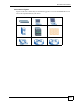
Document Conventions Icons Used in Figures Figures in this User’s Guide may use the following generic icons. The P-660HWP-Dx icon is not an exact representation of your device.
Safety Warnings Safety Warnings 1 For your safety, be sure to read and follow all warning notices and instructions. • Do NOT use this product near water, for example, in a wet basement or near a swimming pool. • Do NOT expose your device to dampness, dust or corrosive liquids. • Do NOT store things on the device. • Do NOT install, use, or service this device during a thunderstorm. There is a remote risk of electric shock from lightning. • Connect ONLY suitable accessories to the device.
Safety Warnings P-660HWP-Dx User’s Guide 39
Safety Warnings 40 P-660HWP-Dx User’s Guide
Contents Overview Contents Overview Introduction ............................................................................................................................ 33 Introducing the P-660HWP-Dx .................................................................................................. 35 Introducing the Web Configurator .............................................................................................. 43 Wizards ................................................................
Contents Overview 36 P-660HWP-Dx User’s Guide
Table of Contents Table of Contents About This User's Guide .......................................................................................................... 3 Document Conventions............................................................................................................ 4 Safety Warnings........................................................................................................................ 6 Contents Overview .......................................................
Table of Contents 2.4.4 Status: WLAN Status .................................................................................................. 52 2.4.5 Status: Bandwidth Status ........................................................................................... 52 2.4.6 Status: Powerline Statistics ........................................................................................ 53 2.4.7 Status: Packet Statistics .................................................................................
Table of Contents 5.5 Internet Connection ............................................................................................................ 86 5.5.1 Configuring Advanced Internet Connection Setup ..................................................... 88 5.6 Configuring More Connections ............................................................................................ 90 5.6.1 More Connections Edit ...........................................................................................
Table of Contents 7.4.5 Wireless LAN Advanced Setup ................................................................................ 122 7.5 OTIST ................................................................................................................................ 123 7.5.1 Enabling OTIST ........................................................................................................ 123 7.5.2 Starting OTIST .................................................................................
Table of Contents Part IV: Security ................................................................................... 155 Chapter 10 Firewalls................................................................................................................................. 157 10.1 Firewall Overview ........................................................................................................... 157 10.2 Types of Firewalls ..........................................................................
Table of Contents 11.8 Predefined Services ......................................................................................................... 183 11.9 Anti-Probing ..................................................................................................................... 185 11.10 DoS Thresholds ............................................................................................................ 186 11.10.1 Threshold Values ............................................................
Table of Contents 14.2 Configuring Static Route ................................................................................................. 219 14.2.1 Static Route Edit ................................................................................................... 220 Chapter 15 Bandwidth Management....................................................................................................... 223 15.1 Bandwidth Management Overview ..........................................................
Table of Contents 17.6.3 Configuring SNMP ................................................................................................. 245 17.7 Configuring DNS ............................................................................................................. 246 17.8 Configuring ICMP ............................................................................................................ 247 17.9 TR-069 ......................................................................................
Table of Contents 21.2 Configuration Screen ....................................................................................................... 291 21.2.1 Backup Configuration ............................................................................................. 291 21.2.2 Restore Configuration ............................................................................................ 292 21.2.3 Back to Factory Defaults ............................................................................
Table of Contents 44 P-660HWP-Dx User’s Guide
List of Figures List of Figures Figure 1 Protected Internet Access Applications .................................................................................... 36 Figure 2 LAN-to-LAN Application Example ............................................................................................ 36 Figure 3 Front Panel .............................................................................................................................. 38 Figure 4 Connecting a POTS Splitter ....................
List of Figures Figure 39 Select a Mode ........................................................................................................................ 74 Figure 40 Wizard: Welcome ................................................................................................................... 75 Figure 41 Bandwidth Management Wizard: General Information ........................................................... 75 Figure 42 Bandwidth Management Wizard: Configuration ............................
List of Figures Figure 82 Network > Powerline > Remote Setting ............................................................................... 139 Figure 83 Network > Powerline > Status .............................................................................................. 140 Figure 84 How NAT Works ................................................................................................................... 144 Figure 85 NAT Application With IP Alias ...........................................
List of Figures Figure 125 Security > Certificates > Directory Server > Add ................................................................ 216 Figure 126 Example of Static Routing Topology ................................................................................... 219 Figure 127 Static Route ........................................................................................................................ 220 Figure 128 Static Route Edit .......................................................
List of Figures Figure 168 Error Message .................................................................................................................... 291 Figure 169 Maintenance > Tools > Configuration ................................................................................. 291 Figure 170 Configuration Restore Successful ...................................................................................... 292 Figure 171 Temporarily Disconnected ..............................................
List of Figures Figure 211 Red Hat 9.0: Checking TCP/IP Properties ........................................................................ 356 Figure 212 Displaying Log Categories Example .................................................................................. 366 Figure 213 Displaying Log Parameters Example ................................................................................. 366 Figure 214 Pop-up Blocker ...............................................................................
List of Tables List of Tables Table 1 ADSL Standards ....................................................................................................................... 36 Table 2 Front Panel LEDs ...................................................................................................................... 38 Table 3 Web Configurator Screens Summary ....................................................................................... 47 Table 4 Status Screen ..................................
List of Tables Table 39 MAC Address Filter ............................................................................................................... 127 Table 40 WMM QoS Priorities ............................................................................................................. 128 Table 41 Commonly Used Services ..................................................................................................... 129 Table 42 Wireless Lan: QoS ..............................................
List of Tables Table 82 Security > Certificates > Directory Server > Add .................................................................. 216 Table 83 Static Route ........................................................................................................................... 220 Table 84 Static Route Edit ................................................................................................................... 221 Table 85 Application and Subnet-based Bandwidth Management Example ....
List of Tables Table 125 Certificate Path Verification Failure Reason Codes ............................................................ 285 Table 126 ACL Setting Notes .............................................................................................................. 285 Table 127 ICMP Notes ......................................................................................................................... 286 Table 128 Syslog Logs ...........................................................
List of Tables Table 168 Firewall Commands ............................................................................................................ 369 Table 169 NetBIOS Filter Default Settings ..........................................................................................
List of Tables 40 P-660HWP-Dx User’s Guide
P ART I Introduction Introducing the P-660HWP-Dx (35) Introducing the Web Configurator (43) 35
36
CHAPTER 1 Introducing the P-660HWP-Dx This chapter introduces the main applications and features of the P-660HWP-Dx. It also introduces the ways you can manage the P-660HWP-Dx. 1.1 Overview The P-660HWP-Dx is an IEEE 802.11b/g wireless ADSL2+ gateway that allows super-fast, secure Internet access over analog (POTS), digital (ISDN) telephone lines (depending on your model) or by wireless. It also complies with the HomePlug AV standard, enabling networking using standard electrical wiring.
Chapter 1 Introducing the P-660HWP-Dx Figure 1 Protected Internet Access Applications H You can also use the P-660HWP-Dx to connect two geographically dispersed networks over the ADSL line. A typical LAN-to-LAN application example is shown as follows. Figure 2 LAN-to-LAN Application Example The P-660HWP-Dx is compatible with the ADSL/ADSL2/ADSL2+ standards. Maximum data rates attainable for each standard are shown in the next table.
Chapter 1 Introducing the P-660HWP-Dx " The standard your ISP supports determines the maximum upstream and downstream speeds attainable. Actual speeds attained also depend on the distance from your ISP, line quality, etc. 1.2 Ways to Manage the P-660HWP-Dx Use any of the following methods to manage the P-660HWP-Dx. • Web Configurator. This is recommended for everyday management of the P-660HWP-Dx using a (supported) web browser. • Command Line Interface.
Chapter 1 Introducing the P-660HWP-Dx Figure 3 Front Panel The following table describes the LEDs. Table 2 Front Panel LEDs LED COLOR STATUS DESCRIPTION POWER Green Red ETHERNET WLAN DSL INTERNET Green Green Green Green Red POWERLINE Green On The P-660HWP-Dx is receiving power and functioning properly. Blinking The P-660HWP-Dx is rebooting or performing diagnostics. On Power to the P-660HWP-Dx is too low. Off The system is receiving power but has malfunctioned.
Chapter 1 Introducing the P-660HWP-Dx 1.5.1 Connecting a POTS Splitter When you use the Full Rate (G.dmt) ADSL standard, you can use a POTS (Plain Old Telephone Service) splitter to separate the telephone and ADSL signals. This allows simultaneous Internet access and telephone service on the same line. A splitter also eliminates the destructive interference conditions caused by telephone sets.
Chapter 1 Introducing the P-660HWP-Dx Figure 5 Connecting a Microfilter You can also use a Y-Connector with a microfilter in order to connect both your modem and a telephone to the same wall jack without using a POTS splitter. 1 Connect a phone cable from the wall jack to the single jack end of the Y-Connector. 2 Connect a cable from the double jack end of the Y-Connector to the “wall side” of the microfilter. 3 Connect another cable from the double jack end of the Y-Connector to the P-660HWPDx.
Chapter 1 Introducing the P-660HWP-Dx Figure 7 P-660HWP-Dx with ISDN P-660HWP-Dx User’s Guide 41
Chapter 1 Introducing the P-660HWP-Dx 42 P-660HWP-Dx User’s Guide
CHAPTER 2 Introducing the Web Configurator This chapter describes how to access and navigate the web configurator. 2.1 Web Configurator Overview The web configurator is an HTML-based management interface that allows easy P-660HWPDx setup and management via Internet browser. Use Internet Explorer 6.0 and later or Netscape Navigator 7.0 and later versions. The recommended screen resolution is 1024 by 768 pixels.
Chapter 2 Introducing the Web Configurator 5 A window displays as shown. Figure 8 Password Screen 2.2.1 User Access 1 For user access enter the default user password user to view the status only. The following window will appear. Figure 9 User status screen 2.2.2 Administrator Access 1 For administrator access enter the default admin password 1234 to configure the wizards and the advanced features.
Chapter 2 Introducing the Web Configurator " If you do not change the password at least once, the following screen appears every time you log in with the admin password. Figure 10 Change Password at Login 4 Select Go to Wizard setup and click Apply to display the wizard main screen. Otherwise, select Go to Advanced setup and click Apply to display the Status screen.
Chapter 2 Introducing the Web Configurator 2.3 Resetting the P-660HWP-Dx If you forget your password or cannot access the web configurator, you will need to use the RESET button at the back of the P-660HWP-Dx to reload the factory-default configuration file. This means that you will lose all configurations that you had previously and the password will be reset to “1234”. 2.3.1 Using the Reset Button 1 Make sure the POWER LED is on (not blinking).
Chapter 2 Introducing the Web Configurator " Click the icon (located in the top right corner of most screens) to view embedded help. Table 3 Web Configurator Screens Summary LINK/ICON SUB-LINK FUNCTION Wizard INTERNET/ WIRELESS SETUP Use these screens for initial configuration including general setup, ISP parameters for Internet Access and WAN IP/DNS Server/MAC address assignment. BANDWIDTH MANAGEMENT SETUP Use these screens to limit bandwidth usage by application or packet type.
Chapter 2 Introducing the Web Configurator Table 3 Web Configurator Screens Summary (continued) LINK/ICON SUB-LINK FUNCTION NAT General Use this screen to enable NAT. Port Forwarding Use this screen to configure servers behind the P-660HWPDx. General Use this screen to activate/deactivate the firewall and the direction of network traffic to which to apply the rule. Rules This screen shows a summary of the firewall rules, and allows you to edit/add a firewall rule.
Chapter 2 Introducing the Web Configurator Table 3 Web Configurator Screens Summary (continued) LINK/ICON SUB-LINK FUNCTION General This screen contains administrative and system-related information and also allows you to change your password. Time Setting Use this screen to change your P-660HWP-Dx’s time and date. View Log Use this screen to view the logs for the categories that you selected. Log Settings Use this screen to change your P-660HWP-Dx’s log settings.
Chapter 2 Introducing the Web Configurator The following table describes the labels shown in the Status screen. Table 4 Status Screen LABEL DESCRIPTION Refresh Interval Select a number of seconds or None from the drop-down list box to refresh all screen statistics automatically at the end of every time interval or to not refresh the screen statistics. Apply Click this button to refresh the status screen statistics.
Chapter 2 Introducing the Web Configurator Table 4 Status Screen (continued) LABEL DESCRIPTION CPU Usage This number shows how many kilobytes of the heap memory the P-660HWP-Dx is using. Heap memory refers to the memory that is not used by ZyNOS (ZyXEL Network Operating System) and is thus available for running processes like NAT, VPN and the firewall. The bar displays what percent of the P-660HWP-Dx's heap memory is in use. The bar turns from green to red when the maximum is being approached.
Chapter 2 Introducing the Web Configurator The following table describes the labels in this screen. Table 5 Status: Any IP Table LABEL DESCRIPTION # This is the index number of the host computer. IP Address This field displays the IP address of the network device. MAC Address This field displays the MAC (Media Access Control) address of the computer with the displayed IP address. Every Ethernet device has a unique MAC address.
Chapter 2 Introducing the Web Configurator Figure 16 Status: Bandwidth Status 2.4.6 Status: Powerline Statistics Click the Powerline Statistics hyperlink in the Status screen. The following screen will appear. Figure 17 Status: Powerline See Figure 46 on page 140 for information on the headings on this screen. 2.4.7 Status: Packet Statistics Click the Packet Statistics hyperlink in the Status screen. Read-only information here includes port status and packet specific statistics.
Chapter 2 Introducing the Web Configurator Figure 18 Status: Packet Statistics The following table describes the fields in this screen. Table 7 Status: Packet Statistics LABEL DESCRIPTION System Monitor System up Time This is the elapsed time the system has been up. Current Date/Time This field displays your P-660HWP-Dx’s present date and time. CPU Usage This field specifies the percentage of CPU utilization. Memory Usage This field specifies the percentage of memory utilization.
Chapter 2 Introducing the Web Configurator Table 7 Status: Packet Statistics (continued) LABEL DESCRIPTION Collisions This is the number of collisions on this port. Poll Interval(s) Type the time interval for the browser to refresh system statistics. Set Interval Click this button to apply the new poll interval you entered in the Poll Interval field above. Stop Click this button to halt the refreshing of the system statistics. 2.4.
Chapter 2 Introducing the Web Configurator 48 P-660HWP-Dx User’s Guide
P ART II Wizards Wizard Setup for Internet/Wireless Access (59) Bandwidth Management Wizard (73) 35
36
CHAPTER 3 Wizard Setup for Internet/ Wireless Access This chapter provides information on the Wizard Setup screens for Internet/Wireless access in the web configurator. 3.1 Introduction Use the wizard setup screens to configure your system for Internet/Wireless access with the information given to you by your ISP. " See the advanced menu chapters for background information on these fields. 3.
Chapter 3 Wizard Setup for Internet/Wireless Access Figure 20 Select a Mode 2 Click INTERNET/WIRELESS SETUP to configure the system for Internet access. Figure 21 Wizard: Welcome 3 The wizard attempts to detect which WAN connection type you are using. If the wizard detects your connection type and your ISP uses PPPoE or PPPoA, go to Section 3.2.1 on page 37. The screen varies depending on the connection type you use.
Chapter 3 Wizard Setup for Internet/Wireless Access Figure 22 Auto Detection: No DSL Connection If the wizard still cannot detect a connection type and the following screen appears (see Figure 23 on page 37), click Next and refer to Section 3.2.2 on page 38 on how to configure the P-660HWP-Dx for Internet access manually. Figure 23 Auto Detection: Failed 3.2.1 Automatic Detection 1 If you have a PPPoE or PPPoA connection, a screen displays prompting you to enter your Internet account information.
Chapter 3 Wizard Setup for Internet/Wireless Access Figure 24 Auto-Detection: PPPoE 3.2.2 Manual Configuration 1 If the P-660HWP-Dx fails to detect your DSL connection type, enter the Internet access information given to you by your ISP exactly in the wizard screen. If not given, leave the fields set to the default.
Chapter 3 Wizard Setup for Internet/Wireless Access The following table describes the fields in this screen. Table 8 Internet Access Wizard Setup: ISP Parameters LABEL DESCRIPTION Mode From the Mode drop-down list box, select Routing (default) if your ISP allows multiple computers to share an Internet account. Otherwise select Bridge. Encapsulation Select the encapsulation type your ISP uses from the Encapsulation drop-down list box. Choices vary depending on what you select in the Mode field.
Chapter 3 Wizard Setup for Internet/Wireless Access The following table describes the fields in this screen. Table 9 Internet Connection with PPPoE LABEL DESCRIPTION User Name Enter the user name exactly as your ISP assigned. If assigned a name in the form user@domain where domain identifies a service name, then enter both components exactly as given. Password Enter the password associated with the user name above. Service Name Type the name of your PPPoE service here.
Chapter 3 Wizard Setup for Internet/Wireless Access Figure 28 Internet Connection with ENET ENCAP The following table describes the fields in this screen. Table 11 Internet Connection with ENET ENCAP LABEL DESCRIPTION Obtain an IP Address Automatically A static IP address is a fixed IP that your ISP gives you. A dynamic IP address is not fixed; the ISP assigns you a different one each time you connect to the Internet. Select Obtain an IP Address Automatically if you have a dynamic IP address.
Chapter 3 Wizard Setup for Internet/Wireless Access Figure 29 Internet Connection with PPPoA The following table describes the fields in this screen. Table 12 Internet Connection with PPPoA LABEL DESCRIPTION User Name Enter the login name that your ISP gives you. Password Enter the password associated with the user name above. Back Click Back to go back to the previous wizard screen. Apply Click Apply to save your changes to the P-660HWP-Dx.
Chapter 3 Wizard Setup for Internet/Wireless Access Figure 31 Connection Test Failed-2. 3.3 Wireless Connection Wizard Setup After you configure the Internet access information, use the following screens to set up your wireless LAN. This section is available on the wireless devices only. 1 Select Yes and click Next to configure wireless settings. Otherwise, select No and skip to Step 6. Figure 32 Connection Test Successful 2 Use this screen to activate the wireless LAN and OTIST. Click Next to continue.
Chapter 3 Wizard Setup for Internet/Wireless Access Figure 33 Wireless LAN Setup Wizard 1 The following table describes the labels in this screen. Table 13 Wireless LAN Setup Wizard 1 LABEL DESCRIPTION Active Select the check box to turn on the wireless LAN. Enable OTIST Select the check box to enable OTIST if you want to transfer your P-660HWPDx’s SSID and WPA-PSK security settings to wireless clients that support OTIST and are within transmission range.
Chapter 3 Wizard Setup for Internet/Wireless Access Figure 34 Wireless LAN Setup Wizard 2 The following table describes the labels in this screen. Table 14 Wireless LAN Setup Wizard 2 LABEL DESCRIPTION Network Name Enter a descriptive name (up to 32 printable 7-bit English keyboard characters) for the (SSID) wireless LAN. If you change this field on the P-660HWP-Dx, make sure all wireless stations use the same SSID in order to access the network.
Chapter 3 Wizard Setup for Internet/Wireless Access " The wireless stations and P-660HWP-Dx must use the same SSID, channel ID and WEP encryption key (if WEP is enabled), WPA-PSK (if WPA-PSK is enabled) for wireless communication. 4 This screen varies depending on the security mode you selected in the previous screen. Fill in the field (if available) and click Next. 3.3.1 Manually assign a WPA-PSK key Choose Manually assign a WPA-PSK key in the Wireless LAN setup screen to set up a PreShared Key.
Chapter 3 Wizard Setup for Internet/Wireless Access Figure 36 Manually assign a WEP key The following table describes the labels in this screen. Table 16 Manually assign a WEP key LABEL DESCRIPTION Key The WEP keys are used to encrypt data. Both the P-660HWP-Dx and the wireless stations must use the same WEP key for data transmission. Enter any 5, 13 or 29 English keyboard characters or 10, 26 or 58 hexadecimal characters ("0-9", "A-F") for a 64-bit, 128-bit or 256-bit WEP key respectively.
Chapter 3 Wizard Setup for Internet/Wireless Access Figure 38 Internet Access and Wireless Wizard Setup Complete 7 Launch your web browser and navigate to www.zyxel.com. Internet access is just the beginning. Refer to the rest of this guide for more detailed information on the complete range of P-660HWP-Dx features. If you cannot access the Internet, open the web configurator again to confirm that the Internet settings you configured in the wizard setup are correct.
CHAPTER 4 Bandwidth Management Wizard This chapter shows you how to configure basic bandwidth management using the wizard screens. 4.1 Introduction Bandwidth management allows you to control the amount of bandwidth going out through the P-660HWP-Dx’s WAN port and prioritize the distribution of the bandwidth according to service bandwidth requirements. This helps keep one service from using all of the available bandwidth and shutting out other users. 4.
Chapter 4 Bandwidth Management Wizard Table 17 Media Bandwidth Management Setup: Services (continued) SERVICE DESCRIPTION NetMeeting (H.323) A multimedia communications product from Microsoft that enables groups to teleconference and videoconference over the Internet. NetMeeting supports VoIP, text chat sessions, a whiteboard, file transfers and application sharing. NetMeeting uses H.323. H.323 is a standard teleconferencing protocol suite that provides audio, data and video conferencing.
Chapter 4 Bandwidth Management Wizard 2 Click BANDWIDTH MANAGEMENT SETUP to configure the system for Internet access. Figure 40 Wizard: Welcome 3 Activate bandwidth management and select to allocate bandwidth to packets based on the service requirements. Figure 41 Bandwidth Management Wizard: General Information The following fields describe the label in this screen.
Chapter 4 Bandwidth Management Wizard Figure 42 Bandwidth Management Wizard: Configuration The following table describes the labels in this screen. Table 19 Bandwidth Management Wizard: Configuration LABEL DESCRIPTION Active Select an entry’s Active check box to turn on bandwidth management for the service/ application. Service These fields display the services names.
Chapter 4 Bandwidth Management Wizard Figure 43 Bandwidth Management Wizard: Complete P-660HWP-Dx User’s Guide 53
Chapter 4 Bandwidth Management Wizard 54 P-660HWP-Dx User’s Guide
P ART III Network WAN Setup (81) LAN Setup (99) Wireless LAN (111) Powerline (135) Network Address Translation (NAT) (143) 35
36
CHAPTER 5 WAN Setup This chapter describes how to configure WAN settings. 5.1 WAN Overview A WAN (Wide Area Network) is an outside connection to another network or the Internet. 5.1.1 Encapsulation Be sure to use the encapsulation method required by your ISP. The P-660HWP-Dx supports the following methods. 5.1.1.1 ENET ENCAP The MAC Encapsulated Routing Link Protocol (ENET ENCAP) is only implemented with the IP network protocol.
Chapter 5 WAN Setup 5.1.1.3 PPPoA PPPoA stands for Point to Point Protocol over ATM Adaptation Layer 5 (AAL5). A PPPoA connection functions like a dial-up Internet connection. The P-660HWP-Dx encapsulates the PPP session based on RFC1483 and sends it through an ATM PVC (Permanent Virtual Circuit) to the Internet Service Provider’s (ISP) DSLAM (digital access multiplexer). Please refer to RFC 2364 for more information on PPPoA. Refer to RFC 1661 for more information on PPP. 5.1.1.
Chapter 5 WAN Setup 5.1.3.2 Scenario 2: One VC, One Protocol (IP) Selecting RFC-1483 encapsulation with VC-based multiplexing requires the least amount of overhead (0 octets). However, if there is a potential need for multiple protocol support in the future, it may be safer to select PPPoA encapsulation instead of RFC-1483, so you do not need to reconfigure either computer later. 5.1.3.
Chapter 5 WAN Setup Do not specify a nailed-up connection unless your telephone company offers flat-rate service or you need a constant connection and the cost is of no concern 5.1.7 NAT NAT (Network Address Translation - NAT, RFC 1631) is the translation of the IP address of a host in a packet, for example, the source address of an outgoing packet, used within one network to a different IP address known within another network. 5.2 Metric The metric represents the "cost of transmission".
Chapter 5 WAN Setup Sustained Cell Rate (SCR) is the mean cell rate of each bursty traffic source. It specifies the maximum average rate at which cells can be sent over the virtual connection. SCR may not be greater than the PCR. Maximum Burst Size (MBS) is the maximum number of cells that can be sent at the PCR. After MBS is reached, cell rates fall below SCR until cell rate averages to the SCR again. At this time, more cells (up to the MBS) can be sent at the PCR again.
Chapter 5 WAN Setup The VBR-nRT (non real-time Variable Bit Rate) type is used with bursty connections that do not require closely controlled delay and delay variation. It is commonly used for "bursty" traffic typical on LANs. PCR and MBS define the burst levels, SCR defines the minimum level. An example of an VBR-nRT connection would be non-time sensitive data file transfers. 5.3.1.3 Unspecified Bit Rate (UBR) The Unspecified Bit Rate (UBR) ATM traffic class is for bursty data transfers.
Chapter 5 WAN Setup Figure 45 Internet Connection (PPPoE) The following table describes the labels in this screen. Table 20 Internet Connection LABEL DESCRIPTION General Name Enter the name of your Internet Service Provider, e.g., MyISP. This information is for identification purposes only. Mode Select Routing (default) from the drop-down list box if your ISP allows multiple computers to share an Internet account. Otherwise select Bridge.
Chapter 5 WAN Setup Table 20 Internet Connection (continued) LABEL DESCRIPTION VPI The valid range for the VPI is 0 to 255. Enter the VPI assigned to you. VCI The valid range for the VCI is 32 to 65535 (0 to 31 is reserved for local management of ATM traffic). Enter the VCI assigned to you. IP Address This option is available if you select Routing in the Mode field. Obtain an IP Address Automatically Select this if you get a dynamic IP address from your Internet Service Provider (ISP).
Chapter 5 WAN Setup Figure 46 Advanced Internet Connection Setup The following table describes the labels in this screen. Table 21 Advanced Internet Connection Setup LABEL DESCRIPTION RIP & Multicast Setup RIP Direction Select the RIP direction from None, Both, In Only and Out Only. RIP Version Select the RIP version from RIP-1, RIP-2B and RIP-2M. Multicast IGMP (Internet Group Multicast Protocol) is a network-layer protocol used to establish membership in a multicast group.
Chapter 5 WAN Setup Table 21 Advanced Internet Connection Setup (continued) LABEL DESCRIPTION Zero Configuration This feature is not applicable/available when you configure the P-660HWP-Dx to use a static WAN IP address or in bridge mode. Select Yes to set the P-660HWP-Dx to automatically detect the Internet connection settings (such as the VCI/VPI numbers and the encapsulation method) from the ISP and make the necessary configuration changes. Select No to disable this feature.
Chapter 5 WAN Setup The following table describes the labels in this screen. Table 22 More Connections LABEL DESCRIPTION # This is the index number of a connection. Active This display whether this connection is activated. Clear the check box to disable the connection. Select the check box to enable it. Name This is the descriptive name for this connection. VPI/VCI This is the VPI and VCI values used for this connection. Encapsulation This is the method of encapsulation used for this connection.
Chapter 5 WAN Setup Figure 48 More Connections Edit The following table describes the labels in this screen. Table 23 More Connections Edit 46 LABEL DESCRIPTION Active Select the check box to activate or clear the check box to deactivate this connection. Name Enter a unique, descriptive name of up to 13 English keyboard characters for this connection. Mode Select Routing from the drop-down list box if your ISP allows multiple computers to share an Internet account.
Chapter 5 WAN Setup Table 23 More Connections Edit (continued) LABEL DESCRIPTION Multiplexing Select the method of multiplexing used by your ISP from the drop-down list. Choices are VC or LLC. By prior agreement, a protocol is assigned a specific virtual circuit, for example, VC1 will carry IP. If you select VC, specify separate VPI and VCI numbers for each protocol.
Chapter 5 WAN Setup 5.6.2 Configuring More Connections Advanced Setup To edit your P-660HWP-Dx's advanced WAN settings, click the Advanced Setup button in the More Connections Edit screen. The screen appears as shown. Figure 49 More Connections Advanced Setup The following table describes the labels in this screen. Table 24 More Connections Advanced Setup LABEL DESCRIPTION RIP & Multicast Setup RIP Direction Select the RIP direction from None, Both, In Only and Out Only.
Chapter 5 WAN Setup 5.7 Traffic Redirect Traffic redirect forwards traffic to a backup gateway when the P-660HWP-Dx cannot connect to the Internet. An example is shown in the figure below. Figure 50 Traffic Redirect Example The following network topology allows you to avoid triangle route security issues when the backup gateway is connected to the LAN. Use IP alias to configure the LAN into two or three logical networks with the P-660HWP-Dx itself as the gateway for each LAN network.
Chapter 5 WAN Setup Figure 52 WAN Backup Setup The following table describes the labels in this screen. Table 25 WAN Backup Setup LABEL DESCRIPTION WAN Backup Setup Backup Type Select the method that the P-660HWP-Dx uses to check the DSL connection. Select DSL Link to have the P-660HWP-Dx check if the connection to the DSLAM is up. Select ICMP to have the P-660HWP-Dx periodically ping the IP addresses configured in the Check WAN IP Address fields.
Chapter 5 WAN Setup Table 25 WAN Backup Setup (continued) LABEL DESCRIPTION Timeout Type the number of seconds (3 recommended) for your P-660HWP-Dx to wait for a ping response from one of the IP addresses in the Check WAN IP Address field before timing out the request. The WAN connection is considered "down" after the P-660HWP-Dx times out the number of times specified in the Fail Tolerance field. Use a higher value in this field if your network is busy or congested.
Chapter 5 WAN Setup 52 P-660HWP-Dx User’s Guide
CHAPTER 6 LAN Setup This chapter describes how to configure LAN settings. 6.1 LAN Overview A Local Area Network (LAN) is a shared communication system to which many computers are attached. A LAN is a computer network limited to the immediate area, usually the same building or floor of a building. The LAN screens can help you configure a LAN DHCP server and manage IP addresses. See Section 6.3 on page 40 to configure the LAN screens. 6.1.
Chapter 6 LAN Setup 6.1.2 DHCP Setup DHCP (Dynamic Host Configuration Protocol, RFC 2131 and RFC 2132) allows individual clients to obtain TCP/IP configuration at start-up from a server. You can configure the P660HWP-Dx as a DHCP server or disable it. When configured as a server, the P-660HWP-Dx provides the TCP/IP configuration for the clients. If you turn DHCP service off, you must have another DHCP server on your LAN, or else the computer must be manually configured. 6.1.2.
Chapter 6 LAN Setup • The ISP tells you the DNS server addresses, usually in the form of an information sheet, when you sign up. If your ISP gives you DNS server addresses, enter them in the DNS Server fields in the DHCP Setup screen. • The P-660HWP-Dx acts as a DNS proxy when the Primary and Secondary DNS Server fields are left as 0.0.0.0 in the DHCP Setup screen. 6.
Chapter 6 LAN Setup You can obtain your IP address from the IANA, from an ISP or it can be assigned from a private network. If you belong to a small organization and your Internet access is through an ISP, the ISP can provide you with the Internet addresses for your local networks. On the other hand, if you are part of a much larger organization, you should consult your network administrator for the appropriate IP addresses.
Chapter 6 LAN Setup 224.0.0.0 is not assigned to any group and is used by IP multicast computers. The address 224.0.0.1 is used for query messages and is assigned to the permanent group of all IP hosts (including gateways). All hosts must join the 224.0.0.1 group in order to participate in IGMP. The address 224.0.0.2 is assigned to the multicast routers group. The P-660HWP-Dx supports both IGMP version 1 (IGMP-v1) and IGMP version 2 (IGMPv2).
Chapter 6 LAN Setup " You must enable NAT/SUA to use the Any IP feature on the P-660HWP-Dx. 6.2.4.1 How Any IP Works Address Resolution Protocol (ARP) is a protocol for mapping an Internet Protocol address (IP address) to a physical machine address, also known as a Media Access Control or MAC address, on the local area network. IP routing table is defined on IP Ethernet devices (the P660HWP-Dx) to decide which hop to use, to help forward data along to its specified destination.
Chapter 6 LAN Setup The following table describes the fields in this screen. Table 26 LAN IP LABEL DESCRIPTION LAN TCP/IP IP Address Enter the IP address of your P-660HWP-Dx in dotted decimal notation, for example, 192.168.1.1 (factory default). IP Subnet Mask Type the subnet mask assigned to you by your ISP (if given). Apply Click Apply to save your changes to the P-660HWP-Dx. Cancel Click Cancel to begin configuring this screen afresh.
Chapter 6 LAN Setup Table 27 Advanced LAN Setup (continued) LABEL DESCRIPTION Active Select the Active check box to enable the Any IP feature. This allows a computer to access the Internet without changing the network settings (such as IP address and subnet mask) of the computer, even when the IP addresses of the computer and the P-660HWP-Dx are not in the same subnet.
Chapter 6 LAN Setup Table 28 DHCP Setup LABEL DESCRIPTION DHCP Setup DHCP If set to Server, your P-660HWP-Dx can assign IP addresses, an IP default gateway and DNS servers to Windows 95, Windows NT and other systems that support the DHCP client. If set to None, the DHCP server will be disabled. If set to Relay, the P-660HWP-Dx acts as a surrogate DHCP server and relays DHCP requests and responses between the remote server and the clients.
Chapter 6 LAN Setup Figure 58 LAN Client List The following table describes the labels in this screen. Table 29 LAN Client List LABEL DESCRIPTION IP Address Enter the IP address that you want to assign to the computer on your LAN with the MAC address specified below. The IP address should be within the range of IP addresses you specified in the DHCP Setup for the DHCP client. MAC Address Enter the MAC address of a computer on your LAN. Add Click Add to add a static DHCP entry.
Chapter 6 LAN Setup When you use IP alias, you can also configure firewall rules to control access between the LAN's logical networks (subnets). " Make sure that the subnets of the logical networks do not overlap. The following figure shows a LAN divided into subnets A, B, and C. Figure 59 Physical Network & Partitioned Logical Networks To change your P-660HWP-Dx’s IP alias settings, click Network > LAN > IP Alias. The screen appears as shown.
Chapter 6 LAN Setup The following table describes the labels in this screen. Table 30 LAN IP Alias 46 LABEL DESCRIPTION IP Alias 1, 2 Select the check box to configure another LAN network for the P-660HWP-Dx. IP Address Enter the IP address of your P-660HWP-Dx in dotted decimal notation. Alternatively, click the right mouse button to copy and/or paste the IP address. IP Subnet Mask Your P-660HWP-Dx will automatically calculate the subnet mask based on the IP address that you assign.
CHAPTER 7 Wireless LAN This chapter discusses how to configure the wireless network settings in your P-660HWP-Dx. See the appendices for more detailed information about wireless networks. 7.1 Wireless Network Overview The following figure provides an example of a wireless network. Figure 61 Example of a Wireless Network The wireless network is the part in the blue circle. In this wireless network, devices A and B are called wireless clients.
Chapter 7 Wireless LAN • Every wireless client in the same wireless network must use security compatible with the AP. Security stops unauthorized devices from using the wireless network. It can also protect the information that is sent in the wireless network. 7.2 Wireless Network Setup If you want to access the Internet wirelessly, you must have an Internet account setup already. 7.2.
Chapter 7 Wireless LAN ( ) WPA2-PSK (TKIP or AES):______________ ( ) WPA2 (TKIP or AES) • Preamble type (if available): auto, short or long To set up your wireless network without an AP or wireless router, make sure wireless network cards/adapters use the same following settings: • • • • • Network type: Ad-Hoc SSID:_____________________ Channel: _________________ wireless standard: IEEE 802.11b, g, b/g or a Security: ( ) None ( ) WEP (64bit, 128bit or 256bit key) (ASCII or Hex):________________ 7.
Chapter 7 Wireless LAN This type of security does not protect the information that is sent in the wireless network. Furthermore, there are ways for unauthorized devices to get the MAC address of an authorized wireless client. Then, they can use that MAC address to use the wireless network. 7.3.3 User Authentication Authentication is the process of verifying whether a wireless device is allowed to use the wireless network. You can make every user log in to the wireless network before they can use it.
Chapter 7 Wireless LAN " It is recommended that wireless networks use WPA-PSK, WPA, or stronger encryption. IEEE 802.1x and WEP encryption are better than none at all, but it is still possible for unauthorized devices to figure out the original information pretty quickly. It is not possible to use WPA-PSK, WPA or stronger encryption with a local user database. In this case, it is better to set up stronger encryption with no authentication than to set up weaker encryption with the local user database.
Chapter 7 Wireless LAN Figure 62 Wireless LAN: General The following table describes the general wireless LAN labels in this screen. Table 32 Wireless LAN: General LABEL DESCRIPTION Wireless Setup Active Wireless LAN Click the check box to activate wireless LAN. Network Name (SSID) (Service Set IDentity) The SSID identifies the Service Set with which a wireless client is associated. Wireless clients associating to the access point (AP) must have the same SSID.
Chapter 7 Wireless LAN " If you do not enable any wireless security on your P-660HWP-Dx, your network is accessible to any wireless networking device that is within range. Figure 63 Wireless: No Security The following table describes the labels in this screen. Table 33 Wireless No Security LABEL DESCRIPTION Security Mode Choose No Security from the drop-down list box. Apply Click Apply to save your changes to the P-660HWP-Dx.
Chapter 7 Wireless LAN Figure 64 Wireless: Static WEP Encryption The following table describes the wireless LAN security labels in this screen. Table 34 Wireless: Static WEP Encryption LABEL DESCRIPTION Security Mode Choose Static WEP from the drop-down list box. Passphrase Enter a Passphrase (up to 32 printable characters) and clicking Generate. The P660HWP-Dx automatically generates a WEP key. WEP Key The WEP keys are used to encrypt data.
Chapter 7 Wireless LAN Figure 65 Wireless: WPA-PSK/WPA2-PSK The following table describes the wireless LAN security labels in this screen. Table 35 Wireless: WPA-PSK/WPA2-PSK LABEL DESCRIPTION Security Mode Choose WPA-PSK or WPA2-PSK from the drop-down list box. WPA Compatible This check box is available only when you select WPA2-PSK or WPA2 in the Security Mode field.
Chapter 7 Wireless LAN Table 35 Wireless: WPA-PSK/WPA2-PSK LABEL DESCRIPTION Group Key Update Timer (In Seconds) The Group Key Update Timer is the rate at which the AP (if using WPA-PSK/ WPA2-PSK key management) or RADIUS server (if using WPA(2) key management) sends a new group key out to all clients. The re-keying process is the WPA(2) equivalent of automatically changing the WEP key for an AP and all stations in a WLAN on a periodic basis.
Chapter 7 Wireless LAN The following table describes the wireless LAN security labels in this screen. Table 36 Wireless: WPA/WPA2 LABEL DESCRIPTION WPA Compatible This check box is available only when you select WPA2-PSK or WPA2 in the Security Mode field. Select the check box to have both WPA2 and WPA wireless clients be able to communicate with the P-660HWP-Dx even when the P-660HWP-Dx is using WPA2-PSK or WPA2.
Chapter 7 Wireless LAN 7.4.5 Wireless LAN Advanced Setup To configure advanced wireless settings, click the Advanced Setup button in the General screen. The screen appears as shown. Figure 67 Advanced The following table describes the labels in this screen. Table 37 Wireless LAN: Advanced LABEL DESCRIPTION Wireless Advanced Setup 46 RTS/CTS Threshold Enter a value between 256 and 2346. Fragmentation Threshold This is the maximum data fragment size that can be sent.
Chapter 7 Wireless LAN Table 37 Wireless LAN: Advanced (continued) LABEL DESCRIPTION Max. Frame Burst Enable Maximum Frame Burst to help eliminate collisions in mixed-mode networks (networks with both IEEE 802.11g and IEEE 802.11b traffic) and enhance the performance of both pure IEEE 802.11g and mixed IEEE 802.11b/g networks. Maximum Frame Burst sets the maximum time, in micro-seconds, that the ZP660HWP-Dx transmits IEEE 802.11g wireless traffic only.
Chapter 7 Wireless LAN " If you hold in the RESET button too long, the device will reset to the factory defaults! 7.5.1.1.2 Web Configurator Click the Network > Wireless LAN > OTIST. The following screen displays. Figure 68 OTIST The following table describes the labels in this screen. Table 38 OTIST LABEL DESCRIPTION Setup Key Type an OTIST Setup Key of exactly eight English keyboard characters in length. The default OTIST setup key is "01234567".
Chapter 7 Wireless LAN Figure 69 Example Wireless Client OTIST Screen 7.5.2 Starting OTIST " You must click Start in the AP OTIST web configurator screen and in the wireless client(s) Adapter screen all within three minutes (at the time of writing). You can start OTIST in the wireless clients and AP in any order but they must all be within range and have OTIST enabled. 1 In the AP, a web configurator screen pops up showing you the security settings to transfer.
Chapter 7 Wireless LAN Figure 72 OTIST in progress (Client) In the wireless client, you see this screen if it can’t find an OTIST-enabled AP (with the same Setup key). Click OK to go back to the ZyXEL utility main screen. Figure 73 No AP with OTIST Found • If there is more than one OTIST-enabled AP within range, you see a screen asking you to select one AP to get settings from. 7.5.3 Notes on OTIST 1 If you enabled OTIST in the wireless client, you see this screen each time you start the utility.
Chapter 7 Wireless LAN 7.6 MAC Filter The MAC filter screen allows you to configure the P-660HWP-Dx to give exclusive access to up to 32 devices (Allow) or exclude up to 32 devices from accessing the P-660HWP-Dx (Deny). Every Ethernet device has a unique MAC (Media Access Control) address. The MAC address is assigned at the factory and consists of six pairs of hexadecimal characters, for example, 00:A0:C5:00:00:02. You need to know the MAC address of the devices to configure this screen.
Chapter 7 Wireless LAN Table 39 MAC Address Filter LABEL DESCRIPTION Set This is the index number of the MAC address. MAC Address Enter the MAC addresses of the wireless client that are allowed or denied access to the P-660HWP-Dx in these address fields. Enter the MAC addresses in a valid MAC address format, that is, six hexadecimal character pairs, for example, 12:34:56:78:9a:bc. Apply Click Apply to save your changes to the P-660HWP-Dx.
Chapter 7 Wireless LAN 7.7.3 Services The commonly used services and port numbers are shown in the following table. Please refer to RFC 1700 for further information about port numbers. Next to the name of the service, two fields appear in brackets. The first field indicates the IP protocol type (TCP, UDP, or ICMP). The second field indicates the IP port number that defines the service. (Note that there may be more than one IP protocol type. For example, look at the DNS service.
Chapter 7 Wireless LAN Table 41 Commonly Used Services 54 SERVICE DESCRIPTION AIM/New-ICQ(TCP:5190) AOL’s Internet Messenger service, used as a listening port by ICQ. AUTH(TCP:113) Authentication protocol used by some servers. BGP(TCP:179) Border Gateway Protocol. BOOTP_CLIENT(UDP:68) DHCP Client. BOOTP_SERVER(UDP:67) DHCP Server. CU-SEEME(TCP/UDP:7648, 24032) A popular videoconferencing solution from White Pines Software.
Chapter 7 Wireless LAN Table 41 Commonly Used Services (continued) SERVICE DESCRIPTION REAL_AUDIO(TCP:7070) A streaming audio service that enables real time sound over the web. REXEC(TCP:514) Remote Execution Daemon. RLOGIN(TCP:513) Remote Login. RTELNET(TCP:107) Remote Telnet. RTSP(TCP/UDP:554) The Real Time Streaming (media control) Protocol (RTSP) is a remote control for multimedia on the Internet. SFTP(TCP:115) Simple File Transfer Protocol.
Chapter 7 Wireless LAN Click Network > Wireless LAN > QoS. The following screen displays. Figure 76 Wireless LAN: QoS The following table describes the fields in this screen. Table 42 Wireless Lan: QoS LABEL DESCRIPTION QoS 56 Enable WMM QoS Select the check box to enable WMM QoS on the P-660HWP-Dx. WMM QoS Policy Select Default to have the P-660HWP-Dx automatically give a service a priority level according to the ToS value in the IP header of packets it sends.
Chapter 7 Wireless LAN 7.8.2 Application Priority Configuration To edit a WMM QoS application entry, click the edit icon ( screen displays. ) under Modify. The following Figure 77 Application Priority Configuration The following table describes the fields in this screen. Table 43 Application Priority Configuration LABEL DESCRIPTION Application Priority Configuration Name Type a description of the application priority.
Chapter 7 Wireless LAN Table 43 Application Priority Configuration (continued) 58 LABEL DESCRIPTION Apply Click Apply to save your changes back to the P-660HWP-Dx. Cancel Click Cancel to return to the previous screen without saving your changes.
CHAPTER 8 Powerline This chapter introduces the main applications and management of the powerline feature. 8.1 Overview The P-660HWP-Dx is a HomePlug AV adaptor integrated DSL product. The P-660HWP-Dx and other HomePlug AV powerline adapters in your network communicate with each other by sending and receiving information over your home’s electrical wiring. The P-660HWP-Dx plugs into an ordinary outlet to create a new network which can extend to any other electrical outlet in any room of a house.
Chapter 8 Powerline In this User’s Guide the electrical wiring network may be referred to as the “powerline network”. 8.2 Privacy and Powerline Adapters When the P-660HWP-Dx communicates with each other HomePlug AV compliant powerline adapters, they use encryption to scramble the information that is sent in the powerline network. Encryption is like a secret code. If you do not know the secret code, you cannot understand the message.
Chapter 8 Powerline In both cases the powerline adapters reside on the same electrical circuit. In scenario A all the powerline adapters can communicate with each other. In scenario B only the adapters with the same NMK can receive and unscramble communication between each other. 8.2.2 Setting Up Multiple Powerline Networks. Multiple powerline networks can coexist on a single powerline circuit.
Chapter 8 Powerline 8.3 Configuring Local Settings Use the Local Setting screen to enter the network password for the network you wish to configure. You can also change the Device Access Key for your P-660HWP-Dx from this screen. Click Network > Powerline to access the settings of your local station. Figure 81 Network > Powerline > Local Setting The following table describes the labels in this screen.
Chapter 8 Powerline LABEL DESCRIPTION Apply Click Apply to apply your changes. The new network password and DAK is applied to the selected P-660HWP-Dx. Note: You must enter the correct Device Access Key (DAK) for the selected powerline adapter before you can make changes to it. Cancel Click this button to cancel any changes you have made. 8.4 Configuring Remote Settings Use this screen to access the other powerline adapters on your network.
Chapter 8 Powerline LABEL DESCRIPTION Login Remote Device Access Key Type the Device Access Key for the device you have selected. The Device Access Key is listed on the device itself. Apply Click Apply to set the new Network Password. The MAC address of the device will disappear from the list until all devices have had their Network Passwords changed. Cancel Click this button to cancel any changes you have made. 8.
Chapter 8 Powerline LABEL DESCRIPTION TEI TEI refers to Terminal Equipment Identifier. In this case the number identifies the CCo on the powerline network. NID NID refers to Network Identifier. This number identifies a network with a common password. SNID SNID refers to Short Network Identifier. This number is a short form of the NID. Local Station Information This section gives information on the adapter (your P-660HWP-Dx) you are using to access the powerline network.
Chapter 8 Powerline 42 P-660HWP-Dx User’s Guide
CHAPTER 9 Network Address Translation (NAT) This chapter discusses how to configure NAT on the P-660HWP-Dx. 9.1 NAT Overview NAT (Network Address Translation - NAT, RFC 1631) is the translation of the IP address of a host in a packet, for example, the source address of an outgoing packet, used within one network to a different IP address known within another network. 9.1.
Chapter 9 Network Address Translation (NAT) 9.1.2 What NAT Does In the simplest form, NAT changes the source IP address in a packet received from a subscriber (the inside local address) to another (the inside global address) before forwarding the packet to the WAN side. When the response comes back, NAT translates the destination address (the inside global address) back to the inside local address before forwarding it to the original inside host.
Chapter 9 Network Address Translation (NAT) Figure 85 NAT Application With IP Alias 9.1.5 NAT Mapping Types NAT supports five types of IP/port mapping. They are: • One to One: In One-to-One mode, the P-660HWP-Dx maps one local IP address to one global IP address. • Many to One: In Many-to-One mode, the P-660HWP-Dx maps multiple local IP addresses to one global IP address.
Chapter 9 Network Address Translation (NAT) The following table summarizes these types. Table 48 NAT Mapping Types TYPE IP MAPPING One-to-One ILA1ÅÆ IGA1 Many-to-One (SUA/PAT) ILA1ÅÆ IGA1 ILA2ÅÆ IGA1 … Many-to-Many Overload ILA1ÅÆ IGA1 ILA2ÅÆ IGA2 ILA3ÅÆ IGA1 ILA4ÅÆ IGA2 … Many-to-Many No Overload ILA1ÅÆ IGA1 ILA2ÅÆ IGA2 ILA3ÅÆ IGA3 … Server Server 1 IPÅÆ IGA1 Server 2 IPÅÆ IGA1 Server 3 IPÅÆ IGA1 9.
Chapter 9 Network Address Translation (NAT) 9.4 NAT General Setup You must create a firewall rule in addition to setting up SUA/NAT, to allow traffic from the WAN to be forwarded through the P-660HWP-Dx. Click Network > NAT to open the following screen. Figure 86 NAT General The following table describes the labels in this screen. Table 49 NAT General LABEL DESCRIPTION Active Network Address Translation (NAT) Select this check box to enable NAT.
Chapter 9 Network Address Translation (NAT) 9.5 Port Forwarding A port forwarding set is a list of inside (behind NAT on the LAN) servers, for example, web or FTP, that you can make visible to the outside world even though NAT makes your whole inside network appear as a single computer to the outside world. You may enter a single port number or a range of port numbers to be forwarded, and the local IP address of the desired server.
Chapter 9 Network Address Translation (NAT) Table 50 Services and Port Numbers SERVICES PORT NUMBER SNMP trap 162 PPTP (Point-to-Point Tunneling Protocol) 1723 9.5.3 Configuring Servers Behind Port Forwarding (Example) Let's say you want to assign ports 21-25 to one FTP, Telnet and SMTP server (A in the example), port 80 to another (B in the example) and assign a default server IP address of 192.168.1.35 to a third (C in the example).
Chapter 9 Network Address Translation (NAT) Figure 88 NAT Port Forwarding The following table describes the fields in this screen. Table 51 NAT Port Forwarding LABEL DESCRIPTION Default Server Setup Default Server In addition to the servers for specified services, NAT supports a default server. A default server receives packets from ports that are not specified in this screen.
Chapter 9 Network Address Translation (NAT) Figure 89 Port Forwarding Rule Setup The following table describes the fields in this screen. Table 52 Port Forwarding Rule Setup LABEL DESCRIPTION Active Click this check box to enable the rule. Service Name Enter a name to identify this port-forwarding rule. Start Port Enter a port number in this field. To forward only one port, enter the port number again in the End Port field.
Chapter 9 Network Address Translation (NAT) rules. For example, if you have already configured rules 1 to 6 in your current set and now you configure rule number 9. In the set summary screen, the new rule will be rule 7, not 9. Now if you delete rule 4, rules 5 to 7 will be pushed up by 1 rule, so old rules 5, 6 and 7 become new rules 4, 5 and 6. To change your P-660HWP-Dx’s address mapping settings, click Network > NAT > Address Mapping to open the following screen.
Chapter 9 Network Address Translation (NAT) 9.7.1 Address Mapping Rule Edit To edit an address mapping rule, click the rule’s edit icon in the Address Mapping screen to display the screen shown next. Figure 91 Edit Address Mapping Rule The following table describes the fields in this screen. Table 54 Edit Address Mapping Rule LABEL DESCRIPTION Type Choose the port mapping type from one of the following. • One-to-One: One-to-One mode maps one local IP address to one global IP address.
Chapter 9 Network Address Translation (NAT) Table 54 Edit Address Mapping Rule (continued) 46 LABEL DESCRIPTION Apply Click Apply to save your changes to the P-660HWP-Dx. Cancel Click Cancel to begin configuring this screen afresh.
P ART IV Security Firewalls (157) Firewall Configuration (169) Content Filtering (191) Certificates (195) 35
36
CHAPTER 10 Firewalls This chapter gives some background information on firewalls and introduces the P-660HWPDx firewall. 10.1 Firewall Overview Originally, the term firewall referred to a construction technique designed to prevent the spread of fire from one room to another. The networking term “firewall” is a system or group of systems that enforces an access-control policy between two networks. It may also be defined as a mechanism used to protect a trusted network from an untrusted network.
Chapter 10 Firewalls 10.2.2 Application-level Firewalls Application-level firewalls restrict access by serving as proxies for external servers. Since they use programs written for specific Internet services, such as HTTP, FTP and telnet, they can evaluate network packets for valid application-specific data.
Chapter 10 Firewalls 10.3.1 Denial of Service Attacks Figure 92 Firewall Application 10.4 Denial of Service Denials of Service (DoS) attacks are aimed at devices and networks with a connection to the Internet. Their goal is not to steal information, but to disable a device or network so users no longer have access to network resources. The P-660HWP-Dx is pre-configured to automatically detect and thwart all known DoS attacks. 10.4.
Chapter 10 Firewalls 10.4.2 Types of DoS Attacks There are four types of DoS attacks: 1 2 3 4 5 Those that exploit bugs in a TCP/IP implementation. Those that exploit weaknesses in the TCP/IP specification. Brute-force attacks that flood a network with useless data. IP Spoofing. "Ping of Death" and "Teardrop" attacks exploit bugs in the TCP/IP implementations of various computer and host systems.
Chapter 10 Firewalls Figure 94 SYN Flood • In a LAND Attack, hackers flood SYN packets into the network with a spoofed source IP address of the targeted system. This makes it appear as if the host computer sent the packets to itself, making the system unavailable while the target system tries to respond to itself. 7 A brute-force attack, such as a "Smurf" attack, targets a feature in the IP specification known as directed or subnet broadcasting, to quickly flood the target network with useless data.
Chapter 10 Firewalls 10.4.2.1 ICMP Vulnerability ICMP is an error-reporting protocol that works in concert with IP. The following ICMP types trigger an alert: Table 56 ICMP Commands That Trigger Alerts 5 REDIRECT 13 TIMESTAMP_REQUEST 14 TIMESTAMP_REPLY 17 ADDRESS_MASK_REQUEST 18 ADDRESS_MASK_REPLY 10.4.2.2 Illegal Commands (NetBIOS and SMTP) The only legal NetBIOS commands are the following - all others are illegal.
Chapter 10 Firewalls are allowed in. The P-660HWP-Dx uses stateful packet inspection to protect the private LAN from hackers and vandals on the Internet. By default, the P-660HWP-Dx’s stateful inspection allows all communications to the Internet that originate from the LAN, and blocks all traffic to the LAN that originates from the Internet. In summary, stateful inspection: • Allows all sessions originating from the LAN (local network) to the WAN (Internet).
Chapter 10 Firewalls 6 Later, an inbound packet reaches the interface. This packet is part of the connection previously established with the outbound packet. The inbound packet is evaluated against the inbound access list, and is permitted because of the temporary access list entry previously created. 7 The packet is inspected by a firewall rule, and the connection's state table entry is updated as necessary.
Chapter 10 Firewalls If an initiation packet originates on the LAN, this means that someone is trying to make a connection from the LAN to the Internet. Assuming that this is an acceptable part of the security policy (as is the case with the default policy), the connection will be allowed. A cache entry is added which includes connection information such as IP addresses, TCP ports, sequence numbers, etc.
Chapter 10 Firewalls 10.6 Guidelines for Enhancing Security with Your Firewall • Change the default password via CLI (Command Line Interpreter) or web configurator. • Limit who can telnet into your router. • Don't enable any local service (such as SNMP or NTP) that you don't use. Any enabled service could present a potential security risk. A determined hacker might be able to find creative ways to misuse the enabled services to access the firewall or the network.
Chapter 10 Firewalls • Always shred confidential information, particularly about your computer, before throwing it away. Some hackers dig through the trash of companies or individuals for information that might help them in an attack. 10.7 Packet Filtering Vs Firewall Below are some comparisons between the P-660HWP-Dx’s filtering and firewall functions. 10.7.1 Packet Filtering: • The router filters packets as they pass through the router’s interface according to the filter rules you designed.
Chapter 10 Firewalls • To selectively block/allow inbound or outbound traffic between inside host/networks and outside host/networks. Remember that filters can not distinguish traffic originating from an inside host or an outside host by IP address. • The firewall performs better than filtering if you need to check many rules. • Use the firewall if you need routine e-mail reports about your system or need to be alerted when attacks occur.
CHAPTER 11 Firewall Configuration This chapter shows you how to enable and configure the P-660HWP-Dx firewall. 11.1 Access Methods The web configurator is, by far, the most comprehensive firewall configuration tool your P660HWP-Dx has to offer. For this reason, it is recommended that you configure your firewall using the web configurator.CLI (Command Line Interpreter) commands provide limited configuration options and are only recommended for advanced users. 11.
Chapter 11 Firewall Configuration " If you configure firewall rules without a good understanding of how they work, you might inadvertently introduce security risks to the firewall and to the protected network. Make sure you test your rules after you configure them. For example, you may create rules to: • Block certain types of traffic, such as IRC (Internet Relay Chat), from the LAN to the Internet.
Chapter 11 Firewall Configuration 3 Is it possible to modify the rule to be more specific? For example, if IRC is blocked for all users, will a rule that blocks just certain users be more effective? 4 Does a rule that allows Internet users access to resources on the LAN create a security vulnerability? For example, if FTP ports (TCP 20, 21) are allowed from the Internet to the LAN, Internet users may be able to connect to computers with running FTP servers.
Chapter 11 Firewall Configuration 11.4.1 LAN to WAN Rules The default rule for LAN to WAN traffic is that all users on the LAN are allowed nonrestricted access to the WAN. When you configure a LAN to WAN rule, you in essence want to limit some or all users from accessing certain services on the WAN. WAN to LAN Rules The default rule for WAN to LAN traffic blocks all incoming connections (WAN to LAN).
Chapter 11 Firewall Configuration The following table describes the labels in this screen. Table 59 Firewall: General LABEL DESCRIPTION Active Firewall Select this check box to activate the firewall. The P-660HWP-Dx performs access control and protects against Denial of Service (DoS) attacks when the firewall is activated. Bypass Triangle Route Select this check box to have the P-660HWP-Dx firewall permit the use of triangle route topology on the network.
Chapter 11 Firewall Configuration Figure 98 Firewall Rules The following table describes the labels in this screen. Table 60 Firewall Rules LABEL DESCRIPTION Firewall Rules Storage Space in Use This read-only bar shows how much of the P-660HWP-Dx's memory for recording firewall rules it is currently using. When you are using 80% or less of the storage space, the bar is green. When the amount of space used is over 80%, the bar is red.
Chapter 11 Firewall Configuration Table 60 Firewall Rules (continued) LABEL DESCRIPTION Log This field shows you whether a log is created when packets match this rule (Yes) or not (No). Modify Click the Edit icon to go to the screen where you can edit the rule. Click the Remove icon to delete an existing firewall rule. A window displays asking you to confirm that you want to delete the firewall rule. Note that subsequent firewall rules move up by one when you take this action.
Chapter 11 Firewall Configuration Figure 99 Firewall: Edit Rule 54 P-660HWP-Dx User’s Guide
Chapter 11 Firewall Configuration The following table describes the labels in this screen. Table 61 Firewall: Edit Rule LABEL DESCRIPTION Active Select this option to enable this firewall rule. Action for Matched Packet Use the drop-down list box to select what the firewall is to do with packets that match this rule. Select Drop to silently discard the packets without sending a TCP reset packet or an ICMP destination-unreachable message to the sender.
Chapter 11 Firewall Configuration Table 61 Firewall: Edit Rule (continued) LABEL DESCRIPTION Apply Click Apply to save your customized settings and exit this screen. Cancel Click Cancel to exit this screen without saving. 11.6.2 Customized Services Configure customized services and port numbers not predefined by the P-660HWP-Dx. For a comprehensive list of port numbers and services, visit the IANA (Internet Assigned Number Authority) website.
Chapter 11 Firewall Configuration Refer to Section 10.1 on page 35 for more information. Figure 101 Firewall: Configure Customized Services The following table describes the labels in this screen. Table 63 Firewall: Configure Customized Services LABEL DESCRIPTION Service Name Type a unique name for your custom port. Service Type Choose the IP port (TCP, UDP or TCP/UDP) that defines your customized port from the drop down list box.
Chapter 11 Firewall Configuration Figure 102 Firewall Example: Rules 3 In the Rules screen, select the index number after that you want to add the rule. For example, if you select “6”, your new rule becomes number 7 and the previous rule 7 (if there is one) becomes rule 8. 4 Click Add to display the firewall rule configuration screen. 5 In the Edit Rule screen, click the Edit Customized Services link to open the Customized Service screen.
Chapter 11 Firewall Configuration Figure 104 Firewall Example: Edit Rule: Destination Address 9 Use the Add >> and Remove buttons between Available Services and Selected Services list boxes to configure it as follows. Click Apply when you are done. " Custom services show up with an “*” before their names in the Services list box and the Rules list box.
Chapter 11 Firewall Configuration Figure 105 Firewall Example: Edit Rule: Select Customized Services On completing the configuration procedure for this Internet firewall rule, the Rules screen should look like the following. Rule 1 allows a “MyService” connection from the WAN to IP addresses 10.0.0.10 through 10.0.0.15 on the LAN.
Chapter 11 Firewall Configuration Figure 106 Firewall Example: Rules: MyService 11.8 Predefined Services The Available Services list box in the Edit Rule screen (see Section 11.6.1 on page 53) displays all predefined services that the P-660HWP-Dx already supports. Next to the name of the service, two fields appear in brackets. The first field indicates the IP protocol type (TCP, UDP, or ICMP). The second field indicates the IP port number that defines the service.
Chapter 11 Firewall Configuration Table 64 Predefined Services (continued) 62 SERVICE DESCRIPTION HTTP(TCP:80) Hyper Text Transfer Protocol - a client/server protocol for the world wide web. HTTPS HTTPS is a secured http session often used in e-commerce. ICQ(UDP:4000) This is a popular Internet chat program. IPSEC_TRANSPORT/ TUNNEL(AH:0) The IPSEC AH (Authentication Header) tunneling protocol uses this service.
Chapter 11 Firewall Configuration Table 64 Predefined Services (continued) SERVICE DESCRIPTION SSH(TCP/UDP:22) Secure Shell Remote Login Program. STRMWORKS(UDP:1558) Stream Works Protocol. SYSLOG(UDP:514) Syslog allows you to send system logs to a UNIX server. TACACS(UDP:49) Login Host Protocol used for (Terminal Access Controller Access Control System). TELNET(TCP:23) Telnet is the login and terminal emulation protocol common on the Internet and in UNIX environments.
Chapter 11 Firewall Configuration The following table describes the labels in this screen. Table 65 Firewall: Anti Probing LABEL DESCRIPTION Respond to PING on The P-660HWP-Dx does not respond to any incoming Ping requests when Disable is selected. Select LAN to reply to incoming LAN Ping requests. Select WAN to reply to incoming WAN Ping requests. Otherwise select LAN & WAN to reply to both incoming LAN and WAN Ping requests. Do Not Respond to Requests for Unauthorized Services.
Chapter 11 Firewall Configuration 11.10.2 Half-Open Sessions An unusually high number of half-open sessions (either an absolute number or measured as the arrival rate) could indicate that a Denial of Service attack is occurring. For TCP, "halfopen" means that the session has not reached the established state-the TCP three-way handshake has not yet been completed (see Figure 93 on page 38). For UDP, "half-open" means that the firewall has detected no return traffic.
Chapter 11 Firewall Configuration Figure 108 Firewall: Threshold The following table describes the labels in this screen. Table 66 Firewall: Threshold LABEL DESCRIPTION DEFAULT VALUES One Minute Low This is the rate of new half-open sessions that causes the firewall to stop deleting halfopen sessions. The P-660HWP-Dx continues to delete half-open sessions as necessary, until the rate of new connection attempts drops below this number. 80 existing half-open sessions.
Chapter 11 Firewall Configuration Table 66 Firewall: Threshold (continued) LABEL DESCRIPTION DEFAULT VALUES Maximum Incomplete High This is the number of existing half-open sessions that causes the firewall to start deleting half-open sessions. When the number of existing half-open sessions rises above this number, the P-660HWP-Dx deletes half-open sessions as required to accommodate new connection requests. Do not set Maximum Incomplete High to lower than the current Maximum Incomplete Low number.
Chapter 11 Firewall Configuration 68 P-660HWP-Dx User’s Guide
CHAPTER 12 Content Filtering This chapter covers how to configure content filtering. 12.1 Content Filtering Overview Internet content filtering allows you to create and enforce Internet access policies tailored to your needs. Content filtering gives you the ability to block web sites that contain key words (that you specify) in the URL. You can set a schedule for when the P-660HWP-Dx performs content filtering.
Chapter 12 Content Filtering The following table describes the labels in this screen. Table 67 Content Filter: Keyword LABEL DESCRIPTION Active Keyword Blocking Select this check box to enable this feature. Block Websites that contain these keywords in the URL: This box contains the list of all the keywords that you have configured the P-660HWP-Dx to block. Delete Highlight a keyword in the box and click Delete to remove it. Clear All Click Clear All to remove all of the keywords from the list.
Chapter 12 Content Filtering The following table describes the labels in this screen. Table 68 Content Filter: Schedule LABEL DESCRIPTION Schedule Select Active Everyday to Block to make the content filtering active everyday. Otherwise, select Edit Daily to Block and configure which days of the week (or everyday) and which time of the day you want the content filtering to be active.
Chapter 12 Content Filtering 72 P-660HWP-Dx User’s Guide
CHAPTER 13 Certificates This chapter gives background information about public-key certificates and explains how to use them. 13.1 Certificates Overview The P-660HWP-Dx can use certificates (also called digital IDs) to authenticate users. Certificates are based on public-private key pairs. A certificate contains the certificate owner’s identity and public key. Certificates provide a way to exchange public keys for use in authentication.
Chapter 13 Certificates Certification authorities maintain directory servers with databases of valid and revoked certificates. A directory of certificates that have been revoked before the scheduled expiration is called a CRL (Certificate Revocation List). The P-660HWP-Dx can check a peer’s certificate against a directory server’s list of revoked certificates. The framework of servers, software, procedures and policies that handles keys is called PKI (public-key infrastructure). 13.1.
Chapter 13 Certificates Figure 113 Certificate Details 4 Use a secure method to verify that the certificate owner has the same information in the Thumbprint Algorithm and Thumbprint fields. The secure method may very based on your situation. Possible examples would be over the telephone or through an HTTPS connection. 13.4 Configuration Summary This section summarizes how to manage certificates on the P-660HWP-Dx.
Chapter 13 Certificates 13.5 My Certificates Click Security > Certificates > My Certificates to open the My Certificates screen. This is the P-660HWP-Dx’s summary list of certificates and certification requests. Certificates display in black and certification requests display in gray. Figure 115 Security > Certificates > My Certificates The following table describes the labels in this screen.
Chapter 13 Certificates Table 70 Security > Certificates > My Certificates (continued) LABEL DESCRIPTION Subject This field displays identifying information about the certificate’s owner, such as CN (Common Name), OU (Organizational Unit or department), O (Organization or company) and C (Country). It is recommended that each certificate have unique subject information.
Chapter 13 Certificates Table 71 Security > Certificates > My Certificates > Edit The following table describes the labels in this screen. Table 72 Security > Certificates > My Certificates > Details 40 LABEL DESCRIPTION Certificate Name This field displays the identifying name of this certificate. If you want to change the name, type up to 31 characters to identify this certificate. You may use any character (not including spaces).
Chapter 13 Certificates Table 72 Security > Certificates > My Certificates > Details (continued) LABEL DESCRIPTION Type This field displays general information about the certificate. CA-signed means that a Certification Authority signed the certificate. Self-signed means that the certificate’s owner signed the certificate (not a certification authority). “X.509” means that this certificate was created and signed according to the ITU-T X.
Chapter 13 Certificates Table 72 Security > Certificates > My Certificates > Details (continued) LABEL DESCRIPTION Back Click Back to go the previous screen Export Click Export to export a file containing your certificate details. Apply Click Apply to save your changes back to the P-660HWP-Dx. You can only change the name, except in the case of a self-signed certificate, which you can also set to be the default self-signed certificate that signs the imported trusted remote host certificates.
Chapter 13 Certificates The following table describes the labels in this screen. Table 73 Security > Certificates > My Certificates > Create LABEL DESCRIPTION Certificate Name Type up to 31 ASCII characters (not including spaces) to identify this certificate. Subject Information Use these fields to record information that identifies the owner of the certificate. You do not have to fill in every field, although the Common Name is mandatory.
Chapter 13 Certificates Table 73 Security > Certificates > My Certificates > Create (continued) LABEL DESCRIPTION Enrollment Protocol Select the certification authority’s enrollment protocol from the drop-down list box. Simple Certificate Enrollment Protocol (SCEP) is a TCP-based enrollment protocol that was developed by VeriSign and Cisco. Certificate Management Protocol (CMP) is a TCP-based enrollment protocol that was developed by the Public Key Infrastructure X.
Chapter 13 Certificates • You can only import a certificate that matches a corresponding certification request that was generated by the P-660HWP-Dx (the certification request contains the private key). The certificate you import replaces the corresponding request in the My Certificates screen. One exception is that you can import a PKCS#12 format certificate without a corresponding certification request since the certificate includes the private key.
Chapter 13 Certificates 13.9 Trusted CAs Click Security > Certificates > Trusted CAs to open the Trusted CAs screen. This screen displays a summary list of certificates of the certification authorities that you have set the P660HWP-Dx to accept as trusted. The P-660HWP-Dx accepts any valid certificate signed by a certification authority on this list as being trustworthy; thus you do not need to import any certificate that is signed by one of these certification authorities.
Chapter 13 Certificates Table 75 Security > Certificates > Trusted CAs (continued) LABEL DESCRIPTION Modify Click the details icon to open a screen with an in-depth list of information about the certificate. Use the export icon to save the certificate to a computer. Click the icon and then Save in the File Download screen. The Save As screen opens, browse to the location that you want to use and click Save. Click the delete icon to remove the certificate.
Chapter 13 Certificates The following table describes the labels in this screen. Table 76 Security > Certificates > Trusted CAs > Details 48 LABEL DESCRIPTION Certificate Name This field displays the identifying name of this certificate. If you want to change the name, type up to 31 characters to identify this key certificate. You may use any character (not including spaces).
Chapter 13 Certificates Table 76 Security > Certificates > Trusted CAs > Details (continued) LABEL DESCRIPTION Subject Alternative Name This field displays the certificate’s owner‘s IP address (IP), domain name (DNS) or e-mail address (EMAIL). Key Usage This field displays for what functions the certificate’s key can be used. For example, “DigitalSignature” means that the key can be used to sign certificates and “KeyEncipherment” means that the key can be used to encrypt text.
Chapter 13 Certificates Figure 120 Security > Certificates > Trusted CAs > Import The following table describes the labels in this screen. Table 77 Security > Certificates > Trusted CAs Import LABEL DESCRIPTION File Path Type in the location of the file you want to upload in this field or click Browse to find it. Browse Click Browse to find the certificate file you want to upload. Back Click Back to go the previous screen Apply Click Apply to save the certificate on the P-660HWP-Dx.
Chapter 13 Certificates The following table describes the labels in this screen. Table 78 Security > Certificates > Trusted Remote Hosts LABEL DESCRIPTION PKI Storage Space in Use This bar displays the percentage of the P-660HWP-Dx’s PKI storage space that is currently in use. When the storage space is almost full, you should consider deleting expired or unnecessary certificates before adding more certificates.
Chapter 13 Certificates " The trusted remote host certificate must be a self-signed certificate; and you must remove any spaces from its filename before you can import it. Figure 122 Security > Certificates > Trusted Remote Hosts > Import The following table describes the labels in this screen. Table 79 Security > Certificates > Trusted Remote Hosts > Import LABEL DESCRIPTION File Path Type in the location of the file you want to upload in this field or click Browse to find it.
Chapter 13 Certificates Figure 123 Security > Certificates > Trusted Remote Hosts > Details The following table describes the labels in this screen. Table 80 Security > Certificates > Trusted Remote Hosts > Details LABEL DESCRIPTION Certification Name This field displays the identifying name of this certificate. If you want to change the name, type up to 31 characters to identify this key certificate. You may use any character (not including spaces).
Chapter 13 Certificates Table 80 Security > Certificates > Trusted Remote Hosts > Details (continued) 54 LABEL DESCRIPTION Subject This field displays information that identifies the owner of the certificate, such as Common Name (CN), Organizational Unit (OU), Organization (O) and Country (C). Issuer This field displays identifying information about the default self-signed certificate on the P-660HWP-Dx that the P-660HWP-Dx uses to sign the trusted remote host certificates.
Chapter 13 Certificates 13.15 Directory Servers Click Security > Certificates > Directory Servers to open the Directory Servers screen. This screen displays a summary list of directory servers (that contain lists of valid and revoked certificates) that have been saved into the P-660HWP-Dx.
Chapter 13 Certificates Figure 125 Security > Certificates > Directory Server > Add The following table describes the labels in this screen. Table 82 Security > Certificates > Directory Server > Add LABEL DESCRIPTION Directory Service Setting Name Type up to 31 ASCII characters (spaces are not permitted) to identify this directory server. Access Protocol Use the drop-down list box to select the access protocol used by the directory server.
P ART V Advanced Static Route (219) Bandwidth Management (223) Dynamic DNS Setup (235) Remote Management Configuration (239) Universal Plug-and-Play (UPnP) (251) 35
36
CHAPTER 14 Static Route This chapter shows you how to configure static routes for your P-660HWP-Dx. 14.1 Static Route Each remote node specifies only the network to which the gateway is directly connected, and the P-660HWP-Dx has no knowledge of the networks beyond. For instance, the P-660HWPDx knows about network N2 in the following figure through remote node Router 1.
Chapter 14 Static Route Figure 127 Static Route The following table describes the labels in this screen. Table 83 Static Route LABEL DESCRIPTION # This is the number of an individual static route. Active Select the check box to activate this static route. Otherwise, clear the check box. Name This is the name that describes or identifies this route. Destination This parameter specifies the IP network address of the final destination. Routing is always based on network number.
Chapter 14 Static Route Figure 128 Static Route Edit The following table describes the labels in this screen. Table 84 Static Route Edit LABEL DESCRIPTION Active This field allows you to activate/deactivate this static route. Route Name Enter the name of the IP static route. Leave this field blank to delete this static route. Destination IP Address This parameter specifies the IP network address of the final destination. Routing is always based on network number.
Chapter 14 Static Route 38 P-660HWP-Dx User’s Guide
CHAPTER 15 Bandwidth Management This chapter contains information about configuring bandwidth management, editing rules and viewing the P-660HWP-Dx’s bandwidth management logs. 15.1 Bandwidth Management Overview ZyXEL’s Bandwidth Management allows you to specify bandwidth management rules based on an application and/or subnet. You can allocate specific amounts of bandwidth capacity (bandwidth budgets) to different bandwidth rules.
Chapter 15 Bandwidth Management Figure 129 Subnet-based Bandwidth Management Example 15.4 Application and Subnet-based Bandwidth Management You could also create bandwidth classes based on a combination of a subnet and an application. The following example table shows bandwidth allocations for application specific traffic from separate LAN subnets.
Chapter 15 Bandwidth Management 15.5.2 Fairness-based Scheduler The P-660HWP-Dx divides bandwidth equally among bandwidth classes when using the fairness-based scheduler; thus preventing one bandwidth class from using all of the interface’s bandwidth. 15.
Chapter 15 Bandwidth Management 15.6.2 Maximize Bandwidth Usage Example Here is an example of a P-660HWP-Dx that has maximize bandwidth usage enabled on an interface. The following table shows each bandwidth class’s bandwidth budget. The classes are set up based on subnets. The interface is set to 10240 kbps. Each subnet is allocated 2048 kbps. The unbudgeted 2048 kbps allows traffic not defined in any of the bandwidth filters to go out when you do not select the maximize bandwidth option.
Chapter 15 Bandwidth Management 15.6.2.2 Fairness-based Allotment of Unused and Unbudgeted Bandwidth The following table shows the amount of bandwidth that each class gets. Table 88 Fairness-based Allotment of Unused and Unbudgeted Bandwidth Example BANDWIDTH CLASSES AND ALLOTMENTS Root Class: 10240 kbps Administration: 1024 kbps Sales: 3072 kbps Marketing: 3072 kbps Research: 3072 kbps Suppose that all of the classes except for the administration class need more bandwidth.
Chapter 15 Bandwidth Management If you use VoIP and NetMeeting at the same time, the device allocates up to 500 Kbps of bandwidth to each of them before it allocates any bandwidth to FTP. As a result, FTP can only use bandwidth when VoIP and NetMeeting do not use all of their allocated bandwidth. Suppose you try to browse the web too. In this case, VoIP, NetMeeting and FTP all have higher priority, so they get to use the bandwidth first.
Chapter 15 Bandwidth Management Table 91 Media Bandwidth Management: Summary (continued) LABEL DESCRIPTION Scheduler Select either Priority-Based or Fairness-Based from the drop-down menu to control the traffic flow. Select Priority-Based to give preference to bandwidth classes with higher priorities. Select Fairness-Based to treat all bandwidth classes equally.
Chapter 15 Bandwidth Management Table 92 Bandwidth Management: Rule Setup (continued) LABEL DESCRIPTION # This is the number of an individual bandwidth management rule. Active This displays whether the rule is enabled. Select this check box to have the P660HWP-Dx apply this bandwidth management rule. Enable a bandwidth management rule to give traffic that matches the rule priority over traffic that does not match the rule.
Chapter 15 Bandwidth Management PHB consists of two types of services: EF (Expedited Forwarding) and AF (Assured Forwarding). EF has higher priority. EF guarantees services with minimal loss and delay. AF has four sub-classes, each with three levels of importance (drop precedence). A high drop precedence means low importance.
Chapter 15 Bandwidth Management The following table describes the labels in this screen. Table 94 Bandwidth Management Rule Configuration LABEL DESCRIPTION Rule Configuration Active Select this check box to have the P-660HWP-Dx apply this bandwidth management rule. Enable a bandwidth management rule to give traffic that matches the rule priority over traffic that does not match the rule.
Chapter 15 Bandwidth Management Table 94 Bandwidth Management Rule Configuration (continued) LABEL DESCRIPTION Destination Subnet Netmask Enter the destination subnet mask. This field is N/A if you do not specify a Destination Address. Refer to the appendices for more information on IP subnetting. Destination Port Enter the port number of the destination. See Table 95 on page 45 for some common services and port numbers. A blank destination IP address means any destination IP address.
Chapter 15 Bandwidth Management 15.11 Bandwidth Monitor To view the P-660HWP-Dx’s bandwidth usage and allotments, click Advanced > Bandwidth MGMT > Monitor. The screen appears as shown. Select an interface from the drop-down list box to view the bandwidth usage of its bandwidth rules. The gray section of the bar represents the percentage of unused bandwidth and the blue color represents the percentage of bandwidth in use. The screen refreshes every few seconds.
CHAPTER 16 Dynamic DNS Setup This chapter discusses how to configure your P-660HWP-Dx to use Dynamic DNS. 16.1 Dynamic DNS Overview Dynamic DNS allows you to update your current dynamic IP address with one or many dynamic DNS services so that anyone can contact you (in NetMeeting, CU-SeeMe, etc.). You can also access your FTP server or Web site on your own computer using a domain name (for instance myhost.dhs.
Chapter 16 Dynamic DNS Setup Figure 135 Dynamic DNS The following table describes the fields in this screen. Table 97 Dynamic DNS LABEL DESCRIPTION Dynamic DNS Setup Active Dynamic DNS Select this check box to use dynamic DNS. Service Provider This is the name of your Dynamic DNS service provider. Dynamic DNS Type Select the type of service that you are registered for from your Dynamic DNS service provider. Host Name Type the domain name assigned to your P-660HWP-Dx by your Dynamic DNS provider.
Chapter 16 Dynamic DNS Setup Table 97 Dynamic DNS (continued) LABEL DESCRIPTION Dynamic DNS server auto detect IP Address Select this option only when there are one or more NAT routers between the P660HWP-Dx and the DDNS server. This feature has the DDNS server automatically detect and use the IP address of the NAT router that has a public IP address. Note: The DDNS server may not be able to detect the proper IP address if there is an HTTP proxy server between the P660HWP-Dx and the DDNS server.
Chapter 16 Dynamic DNS Setup 38 P-660HWP-Dx User’s Guide
CHAPTER 17 Remote Management Configuration This chapter provides information on configuring remote management. 17.1 Remote Management Overview Remote management allows you to determine which services/protocols can access which P660HWP-Dx interface (if any) from which computers. " When you configure remote management to allow management from the WAN, you still need to configure a firewall rule to allow access.
Chapter 17 Remote Management Configuration 17.1.1 Remote Management Limitations Remote management over LAN or WAN will not work when: • You have disabled that service in one of the remote management screens. • The IP address in the Secured Client IP field does not match the client IP address. If it does not match, the P-660HWP-Dx will disconnect the session immediately. • There is already another remote management session with an equal or higher priority running.
Chapter 17 Remote Management Configuration The following table describes the labels in this screen. Table 98 Remote Management: WWW LABEL DESCRIPTION Port You may change the server port number for a service if needed, however you must use the same port number in order to use that service for remote management. Access Status Select the interface(s) through which a computer may access the P-660HWP-Dx using this service.
Chapter 17 Remote Management Configuration 17.4 Configuring Telnet Click Advanced > Remote MGMT > Telnet tab to display the screen as shown. Figure 138 Remote Management: Telnet The following table describes the labels in this screen. Table 99 Remote Management: Telnet LABEL DESCRIPTION Port You may change the server port number for a service if needed, however you must use the same port number in order to use that service for remote management.
Chapter 17 Remote Management Configuration Figure 139 Remote Management: FTP The following table describes the labels in this screen. Table 100 Remote Management: FTP LABEL DESCRIPTION Port You may change the server port number for a service if needed, however you must use the same port number in order to use that service for remote management. Access Status Select the interface(s) through which a computer may access the P-660HWP-Dx using this service.
Chapter 17 Remote Management Configuration Figure 140 SNMP Management Model An SNMP managed network consists of two main types of component: agents and a manager. An agent is a management software module that resides in a managed device (the P-660HWPDx). An agent translates the local management information from the managed device into a form compatible with SNMP. The manager is the console through which network administrators perform network management functions.
Chapter 17 Remote Management Configuration 17.6.2 SNMP Traps The P-660HWP-Dx will send traps to the SNMP manager when any one of the following events occurs: Table 101 SNMP Traps TRAP # TRAP NAME DESCRIPTION 0 coldStart (defined in RFC-1215) A trap is sent after booting (power on). 1 warmStart (defined in RFC-1215) A trap is sent after booting (software reboot).
Chapter 17 Remote Management Configuration The following table describes the labels in this screen. Table 102 Remote Management: SNMP LABEL DESCRIPTION SNMP Port You may change the server port number for a service if needed, however you must use the same port number in order to use that service for remote management. Access Status Select the interface(s) through which a computer may access the P-660HWPDx using this service.
Chapter 17 Remote Management Configuration Figure 142 Remote Management: DNS The following table describes the labels in this screen. Table 103 Remote Management: DNS LABEL DESCRIPTION Port The DNS service port number is 53. Access Status Select the interface(s) through which a computer may send DNS queries to the P660HWP-Dx. Secured Client IP A secured client is a “trusted” computer that is allowed to send DNS queries to the P-660HWP-Dx.
Chapter 17 Remote Management Configuration Figure 143 Remote Management: ICMP The following table describes the labels in this screen. Table 104 Remote Management: ICMP LABEL DESCRIPTION ICMP Internet Control Message Protocol is a message control and error-reporting protocol between a host server and a gateway to the Internet. ICMP uses Internet Protocol (IP) datagrams, but the messages are processed by the TCP/IP software and directly apparent to the application user.
Chapter 17 Remote Management Configuration Follow the procedure below to configure your P-660HWP-Dx to be managed by CNM Access. See the Command Interpreter appendix for information on the command structure and how to access the CLI (Command Line Interface) on the P-660HWP-Dx. " In this example a.b.c.d is the IP address of CNM Access. You must change this value to reflect your actual management server IP address or domain name. See Table 105 on page 45 for detailed descriptions of the commands.
Chapter 17 Remote Management Configuration 46 P-660HWP-Dx User’s Guide
CHAPTER 18 Universal Plug-and-Play (UPnP) This chapter introduces the UPnP feature in the web configurator. 18.1 Introducing Universal Plug and Play Universal Plug and Play (UPnP) is a distributed, open networking standard that uses TCP/IP for simple peer-to-peer network connectivity between devices. A UPnP device can dynamically join a network, obtain an IP address, convey its capabilities and learn about other devices on the network.
Chapter 18 Universal Plug-and-Play (UPnP) When a UPnP device joins a network, it announces its presence with a multicast message. For security reasons, the P-660HWP-Dx allows multicast messages only on the LAN. All UPnP-enabled devices may communicate freely with each other without additional configuration. Disable UPnP if this is not your intention. You must have IIS (Internet Information Services) enabled on the Windows web server for UPnP to work. 18.
Chapter 18 Universal Plug-and-Play (UPnP) Table 106 Configuring UPnP LABEL DESCRIPTION Allow UPnP to pass through Firewall Select this check box to allow traffic from UPnP-enabled applications to bypass the firewall. Clear this check box to have the firewall block all UPnP application packets (for example, MSN packets). Apply Click Apply to save the setting to the P-660HWP-Dx. Cancel Click Cancel to return to the previously saved settings. 18.
Chapter 18 Universal Plug-and-Play (UPnP) Figure 147 Add/Remove Programs: Windows Setup: Communication: Components 4 Click OK to go back to the Add/Remove Programs Properties window and click Next. 5 Restart the computer when prompted. 18.3.2 Installing UPnP in Windows XP Follow the steps below to install the UPnP in Windows XP. 1 Click start and Control Panel. 2 Double-click Network Connections.
Chapter 18 Universal Plug-and-Play (UPnP) Figure 149 Windows Optional Networking Components Wizard 5 In the Networking Services window, select the Universal Plug and Play check box. Figure 150 Networking Services 6 Click OK to go back to the Windows Optional Networking Component Wizard window and click Next. 18.4 Using UPnP in Windows XP Example This section shows you how to use the UPnP feature in Windows XP. You must already have UPnP installed in Windows XP and UPnP activated on the P-660HWP-Dx.
Chapter 18 Universal Plug-and-Play (UPnP) Make sure the computer is connected to a LAN port of the P-660HWP-Dx. Turn on your computer and the P-660HWP-Dx. 18.4.1 Auto-discover Your UPnP-enabled Network Device 1 Click start and Control Panel. Double-click Network Connections. An icon displays under Internet Gateway. 2 Right-click the icon and select Properties.
Chapter 18 Universal Plug-and-Play (UPnP) Figure 152 Internet Connection Properties 4 You may edit or delete the port mappings or click Add to manually add port mappings.
Chapter 18 Universal Plug-and-Play (UPnP) Figure 154 Internet Connection Properties: Advanced Settings: Add " When the UPnP-enabled device is disconnected from your computer, all port mappings will be deleted automatically. 5 Select Show icon in notification area when connected option and click OK. An icon displays in the system tray. Figure 155 System Tray Icon 6 Double-click on the icon to display your current Internet connection status.
Chapter 18 Universal Plug-and-Play (UPnP) Figure 156 Internet Connection Status 18.4.2 Web Configurator Easy Access With UPnP, you can access the web-based configurator on the P-660HWP-Dx without finding out the IP address of the P-660HWP-Dx first. This comes helpful if you do not know the IP address of the P-660HWP-Dx. Follow the steps below to access the web configurator. 1 Click Start and then Control Panel. 2 Double-click Network Connections. 3 Select My Network Places under Other Places.
Chapter 18 Universal Plug-and-Play (UPnP) Figure 157 Network Connections 4 An icon with the description for each UPnP-enabled device displays under Local Network. 5 Right-click on the icon for your P-660HWP-Dx and select Invoke. The web configurator login screen displays.
Chapter 18 Universal Plug-and-Play (UPnP) Figure 158 Network Connections: My Network Places 6 Right-click on the icon for your P-660HWP-Dx and select Properties. A properties window displays with basic information about the P-660HWP-Dx.
Chapter 18 Universal Plug-and-Play (UPnP) 58 P-660HWP-Dx User’s Guide
P ART VI Maintenance and Troubleshooting System (265) Logs (271) Tools (289) Diagnostic (295) Troubleshooting (297) 35
36
CHAPTER 19 System Use this screen to configure the P-660HWP-Dx’s time and date settings. 19.1 General Setup 19.1.1 General Setup and System Name General Setup contains administrative and system-related information. System Name is for identification purposes. However, because some ISPs check this name you should enter your computer's "Computer Name". • In Windows 95/98 click Start, Settings, Control Panel, Network.
Chapter 19 System Figure 160 System General Setup The following table describes the labels in this screen. Table 107 System General Setup LABEL DESCRIPTION General Setup System Name Choose a descriptive name for identification purposes. It is recommended you enter your computer’s “Computer name” in this field. This name can be up to 30 alphanumeric characters long. Spaces are not allowed, but dashes “-” and underscores "_" are accepted. Domain Name Enter the domain name (if you know it) here.
Chapter 19 System Table 107 System General Setup LABEL DESCRIPTION Old Password Type the default admin password (1234) or the existing password you use to access the system for configuring advanced features. New Password Type your new system password (up to 30 characters). Note that as you type a password, the screen displays a (*) for each character you type. After you change the password, use the new password to access the P-660HWP-Dx. Retype to Confirm Type the new password again for confirmation.
Chapter 19 System The following table describes the fields in this screen. Table 108 System Time Setting LABEL DESCRIPTION Current Time and Date Current Time This field displays the time of your P-660HWP-Dx. Each time you reload this page, the P-660HWP-Dx synchronizes the time with the time server. Current Date This field displays the date of your P-660HWP-Dx. Each time you reload this page, the P-660HWP-Dx synchronizes the date with the time server.
Chapter 19 System Table 108 System Time Setting (continued) LABEL DESCRIPTION Start Date Configure the day and time when Daylight Saving Time starts if you selected Enable Daylight Saving. The o'clock field uses the 24 hour format. Here are a couple of examples: Daylight Saving Time starts in most parts of the United States on the first Sunday of April. Each time zone in the United States starts using Daylight Saving Time at 2 A.M. local time.
Chapter 19 System 40 P-660HWP-Dx User’s Guide
CHAPTER 20 Logs This chapter contains information about configuring general log settings and viewing the P660HWP-Dx’s logs. Refer to the appendix for example log message explanations. 20.1 Logs Overview The web configurator allows you to choose which categories of events and/or alerts to have the P-660HWP-Dx log and then display the logs or have the P-660HWP-Dx send them to an administrator (as e-mail) or to a syslog server. 20.1.
Chapter 20 Logs Figure 162 View Log The following table describes the fields in this screen. Table 109 View Log LABEL DESCRIPTION Display The categories that you select in the Log Settings screen display in the drop-down list box. Select a category of logs to view; select All Logs to view logs from all of the log categories that you selected in the Log Settings page.
Chapter 20 Logs Figure 163 Log Settings The following table describes the fields in this screen. Table 110 Log Settings LABEL DESCRIPTION E-mail Log Settings Mail Server Enter the server name or the IP address of the mail server for the e-mail addresses specified below. If this field is left blank, logs and alert messages will not be sent via E-mail. Mail Subject Type a title that you want to be in the subject line of the log e-mail message that the P-660HWP-Dx sends.
Chapter 20 Logs Table 110 Log Settings LABEL DESCRIPTION Enable SMTP Authentication Simple Mail Transfer Protocol is the message-exchange standard for the Internet. SMTP enables you to move messages from one e-mail server to another User Name Enter the login name that your ISP gives you. Password Enter the password associated with the user name.
Chapter 20 Logs Figure 164 E-mail Log Example Subject: Firewall Alert From xxxxx Date: Fri, 07 Apr 2000 10:05:42 From: user@zyxel.com To: user@zyxel.com 1|Apr 7 00 |From:192.168.1.1 To:192.168.1.255 |default policy |forward | 09:54:03 |UDP src port:00520 dest port:00520 |<1,00> | 2|Apr 7 00 |From:192.168.1.131 To:192.168.1.255 |default policy |forward | 09:54:17 |UDP src port:00520 dest port:00520 |<1,00> | 3|Apr 7 00 |From:192.168.1.6 To:10.10.10.
Chapter 20 Logs Table 111 System Maintenance Logs (continued) LOG MESSAGE DESCRIPTION Starting Connectivity Monitor Starting Connectivity Monitor. Time initialized by Daytime Server The router got the time and date from the Daytime server. Time initialized by Time server The router got the time and date from the time server. Time initialized by NTP server The router got the time and date from the NTP server. Connect to Daytime server fail The router was not able to connect to the Daytime server.
Chapter 20 Logs Table 113 Access Control Logs (continued) LOG MESSAGE DESCRIPTION Triangle route packet forwarded: [TCP | UDP | IGMP | ESP | GRE | OSPF] The firewall allowed a triangle route session to pass through. Packet without a NAT table entry blocked: [TCP | UDP | IGMP | ESP | GRE | OSPF] The router blocked a packet that didn't have a corresponding NAT table entry.
Chapter 20 Logs Table 116 ICMP Logs LOG MESSAGE DESCRIPTION Firewall default policy: ICMP , , ICMP access matched the default policy and was blocked or forwarded according to the user's setting. For type and code details, see Table 127 on page 50. Firewall rule [NOT] match: ICMP , , , ICMP access matched (or didn’t match) a firewall rule (denoted by its number) and was blocked or forwarded according to the rule.
Chapter 20 Logs Table 119 UPnP Logs LOG MESSAGE DESCRIPTION UPnP pass through Firewall UPnP packets can pass through the firewall. Table 120 Content Filtering Logs LOG MESSAGE DESCRIPTION %s: Keyword blocking The content of a requested web page matched a user defined keyword. %s: Not in trusted web list The web site is not in a trusted domain, and the router blocks all traffic except trusted domain sites. %s: Forbidden Web site The web site is in the forbidden web site list.
Chapter 20 Logs Table 121 Attack Logs LOG MESSAGE DESCRIPTION attack [TCP | UDP | IGMP | ESP | GRE | OSPF] The firewall detected a TCP/UDP/IGMP/ESP/GRE/OSPF attack. attack ICMP (type:%d, code:%d) The firewall detected an ICMP attack. For type and code details, see Table 127 on page 50. land [TCP | UDP | IGMP | ESP | GRE | OSPF] The firewall detected a TCP/UDP/IGMP/ESP/GRE/OSPF land attack. land ICMP (type:%d, code:%d) The firewall detected an ICMP land attack.
Chapter 20 Logs Table 122 IPSec Logs (continued) LOG MESSAGE DESCRIPTION Rule <%d> idle time out, disconnect The router dropped a connection that had outbound traffic and no inbound traffic for a certain time period. You can use the "ipsec timer chk_conn" CI command to set the time period. The default value is 2 minutes. WAN IP changed to The router dropped all connections with the “MyIP” configured as “0.0.0.0” when the WAN IP address changed.
Chapter 20 Logs Table 123 IKE Logs (continued) 46 LOG MESSAGE DESCRIPTION Recv IKE uses ISAKMP to transmit data. Each ISAKMP packet contains many different types of payloads. All of them show in the LOG. Refer to RFC2408 – ISAKMP for a list of all ISAKMP payload types. Recv Mode request from The router received an IKE negotiation request from the peer address specified. Send Mode request to The router started negotiation with the peer.
Chapter 20 Logs Table 123 IKE Logs (continued) LOG MESSAGE DESCRIPTION Rule [%d] Phase 1 authentication method mismatch The listed rule’s IKE phase 1 authentication method did not match between the router and the peer. Rule [%d] Phase 1 key group mismatch The listed rule’s IKE phase 1 key group did not match between the router and the peer. Rule [%d] Phase 2 protocol mismatch The listed rule’s IKE phase 2 protocol did not match between the router and the peer.
Chapter 20 Logs Table 124 PKI Logs 48 LOG MESSAGE DESCRIPTION Enrollment successful The SCEP online certificate enrollment was successful. The Destination field records the certification authority server IP address and port. Enrollment failed The SCEP online certificate enrollment failed. The Destination field records the certification authority server’s IP address and port.
Chapter 20 Logs Table 125 Certificate Path Verification Failure Reason Codes CODE DESCRIPTION 1 Algorithm mismatch between the certificate and the search constraints. 2 Key usage mismatch between the certificate and the search constraints. 3 Certificate was not valid in the time interval. 4 (Not used) 5 Certificate is not valid. 6 Certificate signature was not verified correctly. 7 Certificate was revoked by a CRL. 8 Certificate was not added to the cache. 9 Certificate decoding failed.
Chapter 20 Logs Table 127 ICMP Notes TYPE CODE Echo Reply 0 0 Echo reply message Destination Unreachable 3 0 Net unreachable 1 Host unreachable 2 Protocol unreachable 3 Port unreachable 4 A packet that needed fragmentation was dropped because it was set to Don't Fragment (DF) 5 Source route failed Source Quench 4 0 A gateway may discard internet datagrams if it does not have the buffer space needed to queue the datagrams for output to the next network on the route to the destination netwo
Chapter 20 Logs Table 128 Syslog Logs LOG MESSAGE DESCRIPTION Mon dd hr:mm:ss hostname src="" dst="" msg="" note="" devID="" cat=" "This message is sent by the system ("RAS" displays as the system name if you haven’t configured one) when the router generates a syslog. The facility is defined in the web MAIN MENU->LOGS->Log Settings page. The severity is the log’s syslog class.
Chapter 20 Logs 52 P-660HWP-Dx User’s Guide
CHAPTER 21 Tools This chapter describes how to upload new firmware, manage configuration and restart your P660HWP-Dx. 21.1 Firmware Upgrade Find firmware at www.zyxel.com in a file that (usually) uses the system model name with a .bin extension, for example, "P-660HWP-Dx.bin". The upload process uses HTTP (Hypertext Transfer Protocol) and may take up to two minutes. After a successful upload, the system will reboot. Only use firmware for your device’s specific model.
Chapter 21 Tools Table 130 Firmware Upgrade (continued) 1 LABEL DESCRIPTION Browse... Click Browse... to find the .bin file you want to upload. Remember that you must decompress compressed (.zip) files before you can upload them. Upload Click Upload to begin the upload process. This process may take up to two minutes. Do NOT turn off the P-660HWP-Dx while firmware upload is in progress! After you see the Firmware Upload in Progress screen, wait two minutes before logging into the P-660HWP-Dx again.
Chapter 21 Tools Figure 168 Error Message 21.2 Configuration Screen Use this screen to manage your the configuration settings on your device. 21.2.1 Backup Configuration Click Maintenance > Tools > Configuration. Information related to factory defaults, backup configuration, and restoring configuration appears as shown next. Figure 169 Maintenance > Tools > Configuration Backup configuration allows you to back up (save) the P-660HWP-Dx’s current configuration to a file on your computer.
Chapter 21 Tools LABEL DESCRIPTION Upload Restore your router to a previous configuration by uploading a previously saved configuration file from your computer. Reset to Factory Default Settings Reset Clear all settings entered by the user and return the router to its original factoryspecified configuration. 21.2.2 Restore Configuration Restore configuration allows you to upload a new or previously saved configuration file from your computer to your P-660HWP-Dx.
Chapter 21 Tools Figure 171 Temporarily Disconnected If you uploaded the default configuration file you may need to change the IP address of your computer to be in the same subnet as that of the default P-660HWP-Dx IP address (192.168.1.1). See the appendix for details on how to set up your computer’s IP address. If the upload was not successful, the following screen will appear. Click Return to go back to the Configuration screen. Figure 172 Configuration Restore Error 21.2.
Chapter 21 Tools 40 P-660HWP-Dx User’s Guide
CHAPTER 22 Diagnostic These read-only screens display information to help you identify problems with the P660HWP-Dx. 22.1 General Diagnostic Click Maintenance > Diagnostic to open the screen shown next. Figure 174 Diagnostic: General The following table describes the fields in this screen. Table 133 Diagnostic: General LABEL DESCRIPTION TCP/IP Address Type the IP address of a computer that you want to ping in order to test a connection.
Chapter 22 Diagnostic 22.2 DSL Line Diagnostic Click Maintenance > Diagnostic > DSL Line to open the screen shown next. Figure 175 Diagnostic: DSL Line The following table describes the fields in this screen. Table 134 Diagnostic: DSL Line LABEL DESCRIPTION ATM Status Click this button to view ATM status. ATM Loopback Test Click this button to start the ATM loopback test. Make sure you have configured at least one PVC with proper VPIs/VCIs before you begin this test.
CHAPTER 23 Troubleshooting This chapter offers some suggestions to solve problems you might encounter. The potential problems are divided into the following categories. • • • • Power, Hardware Connections, and LEDs P-660HWP-Dx Access and Login Internet Access Powerline Issues 23.1 Power, Hardware Connections, and LEDs V The P-660HWP-Dx does not turn on. None of the LEDs turn on. 1 Make sure the P-660HWP-Dx is turned on.
Chapter 23 Troubleshooting 23.2 P-660HWP-Dx Access and Login V I forgot the IP address for the P-660HWP-Dx. 1 The default IP address is 192.168.1.1. 2 If you changed the IP address and have forgotten it, you might get the IP address of the P-660HWP-Dx by looking up the IP address of the default gateway for your computer. To do this in most Windows computers, click Start > Run, enter cmd, and then enter ipconfig.
Chapter 23 Troubleshooting 5 Reset the device to its factory defaults, and try to access the P-660HWP-Dx with the default IP address. See Section 2.3 on page 46. 6 If the problem continues, contact the network administrator or vendor, or try one of the advanced suggestions. Advanced Suggestions • Try to access the P-660HWP-Dx using another service, such as Telnet.
Chapter 23 Troubleshooting 1 Check the hardware connections, and make sure the LEDs are behaving as expected. See the Quick Start Guide and Section 1.4 on page 37. 2 If your ISP gave you Internet connection information, make sure you entered it correctly in the Network > WAN > Internet Connection screen. These fields are case-sensitive, so make sure [Caps Lock] is not on.
Chapter 23 Troubleshooting Advanced Suggestions • Check the settings for bandwidth management. If it is disabled, you might consider activating it. If it is enabled, you might consider changing the allocations. 23.4 Powerline Issues V I cannot start my powerline device. 1 Check your power supply. Powerline adapters operate from the power supplied by your home wiring and cannot operate without a working power supply.
Chapter 23 Troubleshooting 4 Avoid wiring that is old, low quality or with a long wiring path, as this may affect the quality of your powerline signal.
P ART VII Appendices and Index Product Specifications and Wall Mounting (305) Wireless LANs (311) Internal SPTGEN (325) Setting up Your Computer’s IP Address (341) IP Subnetting (357) Command Interpreter (365) Firewall Commands (369) Pop-up Windows, JavaScripts and Java Permissions (375) NetBIOS Filter Commands (381) Triangle Route (383) Legal Information (385) Customer Support (389) Index (395) 35
36
APPENDIX A Product Specifications and Wall Mounting Product Specifications The following tables summarize the P-660HWP-Dx’s hardware and firmware features.
Appendix A Product Specifications and Wall Mounting Table 136 Firmware Specifications FEATURE DESCRIPTION Firmware Upgrade Download new firmware (when available) from the ZyXEL web site and use the web configurator, an FTP or a TFTP tool to put it on the P660HWP-Dx. Note: Only upload firmware for your specific model! 36 Configuration Backup & Restoration Make a copy of the P-660HWP-Dx’s configuration.
Appendix A Product Specifications and Wall Mounting Table 136 Firmware Specifications FEATURE DESCRIPTION Content Filter The P-660HWP-Dx blocks or allows access to web sites that you specify and blocks access to web sites with URLs that contain keywords that you specify. You can define time periods and days during which content filtering is enabled. You can also include or exclude particular computers on your network from content filtering.
Appendix A Product Specifications and Wall Mounting FEATURE DESCRIPTION Output Power Management This allows you to alter the level of power used by the P-660HWP-Dx. For example, when access points are placed closely together power output levels may be reduced. Wireless LAN MAC Address Filtering This service checks the MAC address of a connection with a list of allowed or denied MAC addresses, ensuring only wanted connections are allowed.
Appendix A Product Specifications and Wall Mounting Table 138 Standards Supported (continued) STANDARD DESCRIPTION IEEE 802.1x Port Based Network Access Control. ANSI T1.413, Issue 2 Asymmetric Digital Subscriber Line (ADSL) standard. G dmt(G.992.1) G.992.1 Asymmetrical Digital Subscriber Line (ADSL) Transceivers ITU G.992.1 (G.DMT) ITU standard for ADSL using discrete multitone modulation. ITU G.992.3 (G.dmt.
Appendix A Product Specifications and Wall Mounting Figure 176 Wall-mounting Example The following are dimensions of an M4 tap screw and masonry plug used for wall mounting. All measurements are in millimeters (mm).
APPENDIX B Wireless LANs Wireless LAN Topologies This section discusses ad-hoc and infrastructure wireless LAN topologies. Ad-hoc Wireless LAN Configuration The simplest WLAN configuration is an independent (Ad-hoc) WLAN that connects a set of computers with wireless adapters (A, B, C). Any time two or more wireless adapters are within range of each other, they can set up an independent network, which is commonly referred to as an ad-hoc network or Independent Basic Service Set (IBSS).
Appendix B Wireless LANs Figure 179 Basic Service Set ESS An Extended Service Set (ESS) consists of a series of overlapping BSSs, each containing an access point, with each access point connected together by a wired network. This wired connection between APs is called a Distribution System (DS). This type of wireless LAN topology is called an Infrastructure WLAN. The Access Points not only provide communication with the wired network but also mediate wireless network traffic in the immediate neighborhood.
Appendix B Wireless LANs Figure 180 Infrastructure WLAN Channel A channel is the radio frequency(ies) used by IEEE 802.11a/b/g wireless devices. Channels available depend on your geographical area. You may have a choice of channels (for your region) so you should use a different channel than an adjacent AP (access point) to reduce interference. Interference occurs when radio signals from different access points overlap causing interference and degrading performance.
Appendix B Wireless LANs Figure 181 RTS/CTS When station A sends data to the AP, it might not know that the station B is already using the channel. If these two stations send data at the same time, collisions may occur when both sets of data arrive at the AP at the same time, resulting in a loss of messages for both stations. RTS/CTS is designed to prevent collisions due to hidden nodes.
Appendix B Wireless LANs If the Fragmentation Threshold value is smaller than the RTS/CTS value (see previously) you set then the RTS (Request To Send)/CTS (Clear to Send) handshake will never occur as data frames will be fragmented before they reach RTS/CTS size. Preamble Type Preamble is used to signal that data is coming to the receiver. Short and Long refer to the length of the synchronization field in a packet.
Appendix B Wireless LANs Wireless security methods available on the P-660HWP-Dx are data encryption, wireless client authentication, restricting access by device MAC address and hiding the P-660HWP-Dx identity. The following figure shows the relative effectiveness of these wireless security methods available on your P-660HWP-Dx.
Appendix B Wireless LANs Determines the network services available to authenticated users once they are connected to the network. • Accounting Keeps track of the client’s network activity. RADIUS is a simple package exchange in which your AP acts as a message relay between the wireless client and the network RADIUS server.
Appendix B Wireless LANs For EAP-TLS authentication type, you must first have a wired connection to the network and obtain the certificate(s) from a certificate authority (CA). A certificate (also called digital IDs) can be used to authenticate users and a CA issues certificates and guarantees the identity of each certificate owner. EAP-MD5 (Message-Digest Algorithm 5) MD5 authentication is the simplest one-way authentication method. The authentication server sends a challenge to the wireless client.
Appendix B Wireless LANs Dynamic WEP Key Exchange The AP maps a unique key that is generated with the RADIUS server. This key expires when the wireless connection times out, disconnects or reauthentication times out. A new WEP key is generated each time reauthentication is performed. If this feature is enabled, it is not necessary to configure a default encryption key in the Wireless screen. You may still configure and store keys here, but they will not be used while Dynamic WEP is enabled.
Appendix B Wireless LANs Encryption Both WPA and WPA2 improve data encryption by using Temporal Key Integrity Protocol (TKIP), Message Integrity Check (MIC) and IEEE 802.1x. WPA and WPA2 use Advanced Encryption Standard (AES) in the Counter mode with Cipher block chaining Message authentication code Protocol (CCMP) to offer stronger encryption than TKIP. TKIP uses 128-bit keys that are dynamically generated and distributed by the authentication server.
Appendix B Wireless LANs Wireless Client WPA Supplicants A wireless client supplicant is the software that runs on an operating system instructing the wireless client how to use WPA. At the time of writing, the most widely available supplicant is the WPA patch for Windows XP, Funk Software's Odyssey client. The Windows XP patch is a free download that adds WPA capability to Windows XP's builtin "Zero Configuration" wireless client. However, you must run Windows XP to use it.
Appendix B Wireless LANs 4 The AP and wireless clients use the TKIP or AES encryption process to encrypt data exchanged between them. Figure 183 WPA(2)-PSK Authentication Security Parameters Summary Refer to this table to see what other security parameters you should configure for each Authentication Method/ key management protocol type. MAC address filters are not dependent on how you configure these security features.
Appendix B Wireless LANs Positioning the antennas properly increases the range and coverage area of a wireless LAN. Antenna Characteristics Frequency An antenna in the frequency of 2.4GHz (IEEE 802.11b) or 5GHz(IEEE 802.11a) is needed to communicate efficiently in a wireless LAN. Radiation Pattern A radiation pattern is a diagram that allows you to visualize the shape of the antenna’s coverage area.
Appendix B Wireless LANs For omni-directional antennas mounted on a table, desk, and so on, point the antenna up. For omni-directional antennas mounted on a wall or ceiling, point the antenna down. For a single AP application, place omni-directional antennas as close to the center of the coverage area as possible. For directional antennas, point the antenna in the direction of the desired coverage area.
APPENDIX C Internal SPTGEN This appendix introduces Internal SPTGEN. All menus shown in this appendix are example menus meant to show SPTGEN usage. Actual menus for your product may differ. Internal SPTGEN Overview Internal SPTGEN (System Parameter Table Generator) is a configuration text file useful for efficient configuration of multiple P-660HWP-Dxs.
Appendix C Internal SPTGEN " DO NOT alter or delete any field except parameters in the Input column. This appendix introduces Internal SPTGEN. All menus shown in this appendix are example menus meant to show SPTGEN usage. Actual menus for your product may differ. Internal SPTGEN File Modification - Important Points to Remember Each parameter you enter must be preceded by one “=”sign and one space. Some parameters are dependent on others.
Appendix C Internal SPTGEN Figure 187 Internal SPTGEN FTP Download Example c:\ftp 192.168.1.1 220 PPP FTP version 1.0 ready at Sat Jan 1 03:22:12 2000 User (192.168.1.1:(none)): 331 Enter PASS command Password: 230 Logged in ftp>bin 200 Type I OK ftp> get rom-t ftp>bye c:\edit rom-t (edit the rom-t text file by a text editor and save it) " You can rename your “rom-t” file when you save it to your computer but it must be named “rom-t” when you upload it to your P-660HWP-Dx.
Appendix C Internal SPTGEN Example Internal SPTGEN Menus This section provides example Internal SPTGEN menus. Table 143 Abbreviations Used in the Example Internal SPTGEN Screens Table ABBREVIATION MEANING FIN Field Identification Number FN Field Name PVA Parameter Values Allowed INPUT An example of what you may enter * Applies to the P-660HWP-Dx.
Appendix C Internal SPTGEN Table 145 Menu 3 / Menu 3.2 TCP/IP and DHCP Ethernet Setup FIN FN PVA INPUT 30200001 = DHCP <0(None) | 1(Server) | 2(Relay)> = 0 30200002 = Client IP Pool Starting Address = 192.168.1.33 30200003 = Size of Client IP Pool = 32 30200004 = Primary DNS Server = 0.0.0.0 30200005 = Secondary DNS Server = 0.0.0.0 30200006 = Remote DHCP Server = 0.0.0.0 30200008 = IP Address = 172.21.2.
Appendix C Internal SPTGEN Table 145 Menu 3 30201008 = IP Alias #1 Incoming protocol filters Set 3 = 256 30201009 = IP Alias #1 Incoming protocol filters Set 4 = 256 30201010 = IP Alias #1 Outgoing protocol filters Set 1 = 256 30201011 = IP Alias #1 Outgoing protocol filters Set 2 = 256 30201012 = IP Alias #1 Outgoing protocol filters Set 3 = 256 30201013 = IP Alias #1 Outgoing protocol filters Set 4 = 256 30201014 = IP Alias 2 <0(No) | 1(Yes)> = 0 30201015 = IP Address = 0.0.0.
Appendix C Internal SPTGEN Table 146 Menu 4 Internet Access Setup (continued) 40000001 = ISP <0(No) | 1(Yes)> = 1 40000002 = Active <0(No) | 1(Yes)> = 1 40000003 = ISP's Name 40000004 = Encapsulation <2(PPPOE) | 3(RFC 1483)| 4(PPPoA )| 5(ENET ENCAP)> = 2 40000005 = Multiplexing <1(LLC-based) | 2(VC-based) = 1 40000006 = VPI # = 0 40000007 = VCI # = 35 40000008 = Service Name = any 40000009 = My Login = test@pqa 40000010 = My Password = 1234 40000011 = S
Appendix C Internal SPTGEN Table 146 Menu 4 Internet Access Setup (continued) 40000031= RIP Direction <0(None) | 1(Both) | 2(In Only) | 3(Out Only)> = 0 40000032= RIP Version <0(Rip-1) | 1(Rip-2B) |2(Rip-2M)> = 0 40000033= Nailed-up Connection <0(No) |1(Yes)> = 0 Table 147 Menu 12 / Menu 12.1.
Appendix C Internal SPTGEN Table 148 Menu 15 SUA Server Setup (continued) 150000004 = SUA Server #2 Port Start 150000005 = SUA Server #2 Port End = 0 150000006 = SUA Server #2 Local IP address = 0.0.0.0 150000007 = SUA Server #3 Active <0(No) | 1(Yes)> = 0 150000008 = SUA Server #3 Protocol <0(All)|6(TCP)|17(U DP)> = 0 150000009 = SUA Server #3 Port Start = 0 150000010 = SUA Server #3 Port End = 0 150000011 = SUA Server #3 Local IP address = 0.0.0.
Appendix C Internal SPTGEN Table 148 Menu 15 SUA Server Setup (continued) 150000038 = SUA Server #9 Protocol <0(All)|6(TCP)|17(U DP)> = 0 150000039 = SUA Server #9 Port Start = 0 150000040 = SUA Server #9 Port End = 0 150000041 = SUA Server #9 Local IP address = 0.0.0.
Appendix C Internal SPTGEN Table 149 Menu 21.1 Filter Set #1 (continued) 210101009 = IP Filter Set 1,Rule 1 Src Subnet Mask = 0 210101010 = IP Filter Set 1,Rule 1 Src Port 210101011 = IP Filter Set 1,Rule 1 Src Port Comp <0(none)|1(equal) |2(not equal)|3(less)|4( greater)> = 0 210101013 = IP Filter Set 1,Rule 1 Act Match <1(check next)|2(forward)| 3(drop)> = 3 210101014 = IP Filter Set 1,Rule 1 Act Not Match <1(check next)|2(forward)| 3(drop)> = 1 = 0 / Menu 21.1.1.
Appendix C Internal SPTGEN Table 150 Menu 21.1 Filter Set #2 (continued) FIN FN PVA INPUT 210201001 = IP Filter Set 2, Rule 1 Type <0(none)|2(TCP/ IP)> = 2 210201002 = IP Filter Set 2, Rule 1 Active <0(No)|1(Yes)> = 1 210201003 = IP Filter Set 2, Rule 1 Protocol = 6 210201004 = IP Filter Set 2, Rule 1 Dest IP address = 0.0.0.
Appendix C Internal SPTGEN Table 150 Menu 21.
Appendix C Internal SPTGEN Table 151 Menu 23 System Menus (continued) 230400002 = ReAuthentication Timer (in second) = 555 230400003 = Idle Timeout (in second) = 999 230400004 = Authentication Databases <0(Local User Database Only) |1(RADIUS Only) |2(Local,RADIUS) |3(RADIUS,Local)> = 1 230400005 = Key Management Protocol <0(8021x) |1(WPA) |2(WPAPSK)> = 0 230400006 = Dynamic WEP Key Exchange <0(Disable) |1(64bit WEP) |2(128-bit WEP)> = 0 230400007 = PSK 230400008 = WPA Mixed Mode 230400
Appendix C Internal SPTGEN Command Examples The following are example Internal SPTGEN screens associated with the P-660HWP-Dx’s command interpreter commands. Table 153 Command Examples FIN FN PVA INPUT /ci command (for annex a): wan adsl opencmd FIN FN PVA INPUT 990000001 = ADSL OPMD <0(glite)|1(t1.
Appendix C Internal SPTGEN 50 P-660HWP-Dx User’s Guide
APPENDIX D Setting up Your Computer’s IP Address All computers must have a 10M or 100M Ethernet adapter card and TCP/IP installed. Windows 95/98/Me/NT/2000/XP, Macintosh OS 7 and later operating systems and all versions of UNIX/LINUX include the software components you need to install and use TCP/ IP on your computer. Windows 3.1 requires the purchase of a third-party TCP/IP application package.
Appendix D Setting up Your Computer’s IP Address Figure 189 WIndows 95/98/Me: Network: Configuration Installing Components The Network window Configuration tab displays a list of installed components. You need a network adapter, the TCP/IP protocol and Client for Microsoft Networks. If you need the adapter: 1 In the Network window, click Add. 2 Select Adapter and then click Add. 3 Select the manufacturer and model of your network adapter and then click OK.
Appendix D Setting up Your Computer’s IP Address Configuring 1 In the Network window Configuration tab, select your network adapter's TCP/IP entry and click Properties 2 Click the IP Address tab. • If your IP address is dynamic, select Obtain an IP address automatically. • If you have a static IP address, select Specify an IP address and type your information into the IP Address and Subnet Mask fields. Figure 190 Windows 95/98/Me: TCP/IP Properties: IP Address 3 Click the DNS Configuration tab.
Appendix D Setting up Your Computer’s IP Address Figure 191 Windows 95/98/Me: TCP/IP Properties: DNS Configuration 4 Click the Gateway tab. • If you do not know your gateway’s IP address, remove previously installed gateways. • If you have a gateway IP address, type it in the New gateway field and click Add. 5 Click OK to save and close the TCP/IP Properties window. 6 Click OK to close the Network window. Insert the Windows CD if prompted. 7 Turn on your P-660HWP-Dx and restart your computer when prompted.
Appendix D Setting up Your Computer’s IP Address Figure 192 Windows XP: Start Menu 2 In the Control Panel, double-click Network Connections (Network and Dial-up Connections in Windows 2000/NT). Figure 193 Windows XP: Control Panel 3 Right-click Local Area Connection and then click Properties.
Appendix D Setting up Your Computer’s IP Address Figure 194 Windows XP: Control Panel: Network Connections: Properties 4 Select Internet Protocol (TCP/IP) (under the General tab in Win XP) and then click Properties. Figure 195 Windows XP: Local Area Connection Properties 5 The Internet Protocol TCP/IP Properties window opens (the General tab in Windows XP). • If you have a dynamic IP address click Obtain an IP address automatically.
Appendix D Setting up Your Computer’s IP Address Figure 196 Windows XP: Internet Protocol (TCP/IP) Properties 6 If you do not know your gateway's IP address, remove any previously installed gateways in the IP Settings tab and click OK. Do one or more of the following if you want to configure additional IP addresses: • In the IP Settings tab, in IP addresses, click Add. • In TCP/IP Address, type an IP address in IP address and a subnet mask in Subnet mask, and then click Add.
Appendix D Setting up Your Computer’s IP Address Figure 197 Windows XP: Advanced TCP/IP Properties 7 In the Internet Protocol TCP/IP Properties window (the General tab in Windows XP): • Click Obtain DNS server address automatically if you do not know your DNS server IP address(es). • If you know your DNS server IP address(es), click Use the following DNS server addresses, and type them in the Preferred DNS server and Alternate DNS server fields.
Appendix D Setting up Your Computer’s IP Address Figure 198 Windows XP: Internet Protocol (TCP/IP) Properties 8 Click OK to close the Internet Protocol (TCP/IP) Properties window. 9 Click Close (OK in Windows 2000/NT) to close the Local Area Connection Properties window. 10 Close the Network Connections window (Network and Dial-up Connections in Windows 2000/NT). 11 Turn on your P-660HWP-Dx and restart your computer (if prompted).
Appendix D Setting up Your Computer’s IP Address Figure 199 Macintosh OS 8/9: Apple Menu 2 Select Ethernet built-in from the Connect via list. Figure 200 Macintosh OS 8/9: TCP/IP 3 For dynamically assigned settings, select Using DHCP Server from the Configure: list. 4 For statically assigned settings, do the following: • From the Configure box, select Manually.
Appendix D Setting up Your Computer’s IP Address • Type your IP address in the IP Address box. • Type your subnet mask in the Subnet mask box. • Type the IP address of your P-660HWP-Dx in the Router address box. 5 Close the TCP/IP Control Panel. 6 Click Save if prompted, to save changes to your configuration. 7 Turn on your P-660HWP-Dx and restart your computer (if prompted). Verifying Settings Check your TCP/IP properties in the TCP/IP Control Panel window.
Appendix D Setting up Your Computer’s IP Address Figure 202 Macintosh OS X: Network 4 For statically assigned settings, do the following: • From the Configure box, select Manually. • Type your IP address in the IP Address box. • Type your subnet mask in the Subnet mask box. • Type the IP address of your P-660HWP-Dx in the Router address box. 5 Click Apply Now and close the window. 6 Turn on your P-660HWP-Dx and restart your computer (if prompted).
Appendix D Setting up Your Computer’s IP Address " Make sure you are logged in as the root administrator. Using the K Desktop Environment (KDE) Follow the steps below to configure your computer IP address using the KDE. 1 Click the Red Hat button (located on the bottom left corner), select System Setting and click Network. Figure 203 Red Hat 9.0: KDE: Network Configuration: Devices 2 Double-click on the profile of the network card you wish to configure.
Appendix D Setting up Your Computer’s IP Address • If you have a dynamic IP address click Automatically obtain IP address settings with and select dhcp from the drop down list. • If you have a static IP address click Statically set IP Addresses and fill in the Address, Subnet mask, and Default Gateway Address fields. 3 Click OK to save the changes and close the Ethernet Device General screen. 4 If you know your DNS server IP address(es), click the DNS tab in the Network Configuration screen.
Appendix D Setting up Your Computer’s IP Address Figure 207 Red Hat 9.0: Dynamic IP Address Setting in ifconfig-eth0 DEVICE=eth0 ONBOOT=yes BOOTPROTO=dhcp USERCTL=no PEERDNS=yes TYPE=Ethernet • If you have a static IP address, enter static in the BOOTPROTO= field. Type IPADDR= followed by the IP address (in dotted decimal notation) and type NETMASK= followed by the subnet mask. The following example shows an example where the static IP address is 192.168.1.10 and the subnet mask is 255.255.255.0.
Appendix D Setting up Your Computer’s IP Address Verifying Settings Enter ifconfig in a terminal screen to check your TCP/IP properties. Figure 211 Red Hat 9.0: Checking TCP/IP Properties [root@localhost]# ifconfig eth0 Link encap:Ethernet HWaddr 00:50:BA:72:5B:44 inet addr:172.23.19.129 Bcast:172.23.19.255 Mask:255.255.255.
APPENDIX E IP Subnetting This appendix introduces addresses, IP address classes and subnet masks. Introduction to IP Addresses An IP address is made up of four octets, written in dotted decimal notation (for example, 192.168.1.1). An octet is an 8-digit binary number. Therefore, each octet has a possible range of 00000000 to 11111111 in binary, or 0 to 256 in decimal. An IP address has two parts: the network number and the host ID.
Appendix E IP Subnetting IP Address Classes and Network ID The value of the first octet of an IP address determines the class of an address. • • • • Class A addresses have a 0 in the leftmost bit. Class B addresses have a 1 in the leftmost bit and a 0 in the next leftmost bit. Class C addresses start with 1 1 0 in the first three leftmost bits. Class D addresses begin with 1 1 1 0. Class D addresses are used for multicasting, which is used to send information to groups of computers.
Appendix E IP Subnetting By convention, subnet masks always consist of a continuous sequence of ones beginning from the leftmost bit of the mask, followed by a continuous sequence of zeros, for a total number of 32 bits. Since the mask is always a continuous number of ones beginning from the left, followed by a continuous number of zeros for the remainder of the 32 bit mask, you can simply specify the number of ones instead of writing the value of each octet.
Appendix E IP Subnetting " In the following charts, shaded/bolded last octet bit values indicate host ID bits “borrowed” to make network ID bits. The number of “borrowed” host ID bits determines the number of subnets you can have. The remaining number of host ID bits (after “borrowing”) determines the number of hosts you can have on each subnet. Table 159 Subnet 1 IP/SUBNET MASK NETWORK NUMBER LAST OCTET BIT VALUE IP Address 192.168.1. 0 IP Address (Binary) 11000000.10101000.00000001.
Appendix E IP Subnetting Example: Four Subnets The above example illustrated using a 25-bit subnet mask to divide a class “C” address space into two subnets. Similarly to divide a class “C” address into four subnets, you need to “borrow” two host ID bits to give four possible combinations (00, 01, 10 and 11). The subnet mask is 26 bits (11111111.11111111.11111111.11000000) or 255.255.255.192.
Appendix E IP Subnetting Example Eight Subnets Similarly use a 27-bit mask to create eight subnets (000, 001, 010, 011, 100, 101, 110 and 111). The following table shows class C IP address last octet values for each subnet.
Appendix E IP Subnetting Table 167 Class B Subnet Planning (continued) NO. “BORROWED” HOST BITS SUBNET MASK NO. SUBNETS NO. HOSTS PER SUBNET 4 255.255.240.0 (/20) 16 4094 5 255.255.248.0 (/21) 32 2046 6 255.255.252.0 (/22) 64 1022 7 255.255.254.0 (/23) 128 510 8 255.255.255.0 (/24) 256 254 9 255.255.255.128 (/25) 512 126 10 255.255.255.192 (/26) 1024 62 11 255.255.255.224 (/27) 2048 30 12 255.255.255.240 (/28) 4096 14 13 255.255.255.248 (/29) 8192 6 14 255.255.
Appendix E IP Subnetting 42 P-660HWP-Dx User’s Guide
APPENDIX F Command Interpreter The following describes how to use the command interpreter. You can telnet to access the CLI (Command Line Interface) on the P-660HWP-Dx. See the included disk or zyxel.com for more detailed information on these commands. 1 Use of undocumented commands or misconfiguration can damage the unit and possibly render it unusable. Accessing the CLI Use the following steps to telnet into your P-660HWP-Dx. 1 Connect your computer to the ETHERNET port on the P-660HWP-Dx.
Appendix F Command Interpreter Log Commands This section provides some general examples of how to use the log commands. The items that display with your device may vary but the basic function should be the same. Go to the command interpreter interface. Configuring What You Want the P-660HWP-Dx to Log 1 Use the sys logs load command to load the log setting buffer that allows you to configure which logs the P-660HWP-Dx is to record. 2 Use sys logs category to view a list of the log categories.
Appendix F Command Interpreter • Use the sys logs display [log category] command to show the logs in an individual P660HWP-Dx log category. • Use the sys logs clear command to erase all of the P-660HWP-Dx’s logs. Log Command Example This example shows how to set the P-660HWP-Dx to record the access logs and alerts and then view the results. ras> ras> ras> ras> sys sys sys sys logs logs logs logs #.time load category access 3 save display access source message 0|06/08/2004 05:58:21 |172.21.4.
Appendix F Command Interpreter 38 P-660HWP-Dx User’s Guide
APPENDIX G Firewall Commands The following describes the firewall commands. Table 168 Firewall Commands FUNCTION COMMAND DESCRIPTION config edit firewall active This command turns the firewall on or off. config retrieve firewall This command returns the previously saved firewall settings. config save firewall This command saves the current firewall settings. config display firewall This command shows the of all the firewall settings including e-mail, attack, and the sets/ rules.
Appendix G Firewall Commands Table 168 Firewall Commands (continued) FUNCTION COMMAND DESCRIPTION config edit firewall e-mail mail-server This command sets the IP address to which the e-mail messages are sent. config edit firewall e-mail return-addr This command sets the source e-mail address of the firewall e-mails. config edit firewall e-mail email-to This command sets the e-mail address to which the firewall e-mails are sent.
Appendix G Firewall Commands Table 168 Firewall Commands (continued) FUNCTION Sets COMMAND DESCRIPTION config edit firewall attack minute-high <0-255> This command sets the threshold rate of new half-open sessions per minute where the P660HWP-Dx starts deleting old half-opened sessions until it gets them down to the minute-low threshold. config edit firewall attack minute-low <0-255> This command sets the threshold of half-open sessions where the P-660HWP-Dx stops deleting half-opened sessions.
Appendix G Firewall Commands Table 168 Firewall Commands (continued) FUNCTION Rules 38 COMMAND DESCRIPTION Config edit firewall set tcp-idle-timeout This command sets how long P-660HWP-Dx lets an inactive TCP connection remain open before considering it closed. Config edit firewall set log This command sets whether or not the P660HWP-Dx creates logs for packets that match the firewall’s default rule set.
Appendix G Firewall Commands Table 168 Firewall Commands (continued) FUNCTION COMMAND DESCRIPTION config edit firewall set rule destaddrsingle This command sets the rule to have the P660HWP-Dx check for traffic with this individual destination address.
Appendix G Firewall Commands Table 168 Firewall Commands (continued) FUNCTION 40 COMMAND DESCRIPTION config delete firewall set rule This command removes the specified rule in a firewall configuration set.
APPENDIX H Pop-up Windows, JavaScripts and Java Permissions In order to use the web configurator you need to allow: • Web browser pop-up windows from your device. • JavaScripts (enabled by default). • Java permissions (enabled by default). " Internet Explorer 6 screens are used here. Screens for other Internet Explorer versions may vary. Internet Explorer Pop-up Blockers You may have to disable pop-up blocking to log into your device.
Appendix H Pop-up Windows, JavaScripts and Java Permissions 2 Clear the Block pop-ups check box in the Pop-up Blocker section of the screen. This disables any web pop-up blockers you may have enabled. Figure 215 Internet Options: Privacy 3 Click Apply to save this setting. Enable pop-up Blockers with Exceptions Alternatively, if you only want to allow pop-up windows from your device, see the following steps. 1 In Internet Explorer, select Tools, Internet Options and then the Privacy tab.
Appendix H Pop-up Windows, JavaScripts and Java Permissions Figure 216 Internet Options: Privacy 3 Type the IP address of your device (the web page that you do not want to have blocked) with the prefix “http://”. For example, http://192.168.167.1. 4 Click Add to move the IP address to the list of Allowed sites.
Appendix H Pop-up Windows, JavaScripts and Java Permissions 5 Click Close to return to the Privacy screen. 6 Click Apply to save this setting. JavaScripts If pages of the web configurator do not display properly in Internet Explorer, check that JavaScripts are allowed. 1 In Internet Explorer, click Tools, Internet Options and then the Security tab. Figure 218 Internet Options: Security 2 3 4 5 6 38 Click the Custom Level... button. Scroll down to Scripting.
Appendix H Pop-up Windows, JavaScripts and Java Permissions Figure 219 Security Settings - Java Scripting Java Permissions 1 2 3 4 5 From Internet Explorer, click Tools, Internet Options and then the Security tab. Click the Custom Level... button. Scroll down to Microsoft VM. Under Java permissions make sure that a safety level is selected. Click OK to close the window.
Appendix H Pop-up Windows, JavaScripts and Java Permissions JAVA (Sun) 1 From Internet Explorer, click Tools, Internet Options and then the Advanced tab. 2 Make sure that Use Java 2 for
APPENDIX I NetBIOS Filter Commands The following describes the NetBIOS packet filter commands. Introduction NetBIOS (Network Basic Input/Output System) are TCP or UDP broadcast packets that enable a computer to connect to and communicate with a LAN. For some dial-up services such as PPPoE or PPTP, NetBIOS packets cause unwanted calls. You can configure NetBIOS filters to do the following: • Allow or disallow the sending of NetBIOS packets from the LAN to the WAN and from the WAN to the LAN.
Appendix I NetBIOS Filter Commands The filter types and their default settings are as follows. Table 169 NetBIOS Filter Default Settings NAME DESCRIPTION EXAMPLE Between LAN and WAN This field displays whether NetBIOS packets are blocked or forwarded between the LAN and the WAN. Block IPSec Packets This field displays whether NetBIOS packets sent through a VPN connection are blocked or forwarded.
APPENDIX J Triangle Route The Ideal Setup When the firewall is on, your P-660HWP-Dx acts as a secure gateway between your LAN and the Internet. In an ideal network topology, all incoming and outgoing network traffic passes through the P-660HWP-Dx to protect your LAN against attacks. Figure 222 Ideal Setup The “Triangle Route” Problem A traffic route is a path for sending or receiving data packets between two Ethernet devices. Some companies have more than one route to one or more ISPs.
Appendix J Triangle Route Figure 223 “Triangle Route” Problem The “Triangle Route” Solutions This section presents you two solutions to the “triangle route” problem. IP Aliasing IP alias allows you to partition your network into logical sections over the same Ethernet interface. Your P-660HWP-Dx supports up to three logical LAN interfaces with the P660HWP-Dx being the gateway for each logical network.
APPENDIX K Legal Information Copyright Copyright © 2007 by ZyXEL Communications Corporation. The contents of this publication may not be reproduced in any part or as a whole, transcribed, stored in a retrieval system, translated into any language, or transmitted in any form or by any means, electronic, mechanical, magnetic, optical, chemical, photocopying, manual, or otherwise, without the prior written permission of ZyXEL Communications Corporation. Published by ZyXEL Communications Corporation.
Appendix K Legal Information If this device does cause harmful interference to radio/television reception, which can be determined by turning the device off and on, the user is encouraged to try to correct the interference by one or more of the following measures: 1 Reorient or relocate the receiving antenna. 2 Increase the separation between the equipment and the receiver. 3 Connect the equipment into an outlet on a circuit different from that to which the receiver is connected.
Appendix K Legal Information ZyXEL Limited Warranty ZyXEL warrants to the original end user (purchaser) that this product is free from any defects in materials or workmanship for a period of up to two years from the date of purchase.
Appendix K Legal Information 38 P-660HWP-Dx User’s Guide
APPENDIX L Customer Support Please have the following information ready when you contact customer support. Required Information • • • • Product model and serial number. Warranty Information. Date that you received your device. Brief description of the problem and the steps you took to solve it. “+” is the (prefix) number you dial to make an international telephone call. Corporate Headquarters (Worldwide) • • • • • • • Support E-mail: support@zyxel.com.tw Sales E-mail: sales@zyxel.com.
Appendix L Customer Support • Regular Mail: ZyXEL Communications, Czech s.r.o., Modranská 621, 143 01 Praha 4 Modrany, Ceská Republika Denmark • • • • • • Support E-mail: support@zyxel.dk Sales E-mail: sales@zyxel.dk Telephone: +45-39-55-07-00 Fax: +45-39-55-07-07 Web: www.zyxel.dk Regular Mail: ZyXEL Communications A/S, Columbusvej, 2860 Soeborg, Denmark Finland • • • • • • Support E-mail: support@zyxel.fi Sales E-mail: sales@zyxel.fi Telephone: +358-9-4780-8411 Fax: +358-9-4780-8448 Web: www.zyxel.
Appendix L Customer Support India • • • • • • Support E-mail: support@zyxel.in Sales E-mail: sales@zyxel.in Telephone: +91-11-30888144 to +91-11-30888153 Fax: +91-11-30888149, +91-11-26810715 Web: http://www.zyxel.in Regular Mail: India - ZyXEL Technology India Pvt Ltd., II-Floor, F2/9 Okhla Phase -1, New Delhi 110020, India Japan • • • • • • Support E-mail: support@zyxel.co.jp Sales E-mail: zyp@zyxel.co.jp Telephone: +81-3-6847-3700 Fax: +81-3-6847-3705 Web: www.zyxel.co.
Appendix L Customer Support • Regular Mail: ZyXEL Communications Inc., 1130 N. Miller St., Anaheim, CA 928062001, U.S.A. Norway • • • • • • Support E-mail: support@zyxel.no Sales E-mail: sales@zyxel.no Telephone: +47-22-80-61-80 Fax: +47-22-80-61-81 Web: www.zyxel.no Regular Mail: ZyXEL Communications A/S, Nils Hansens vei 13, 0667 Oslo, Norway Poland • • • • • E-mail: info@pl.zyxel.com Telephone: +48-22-333 8250 Fax: +48-22-333 8251 Web: www.pl.zyxel.com Regular Mail: ZyXEL Communications, ul.
Appendix L Customer Support Sweden • • • • • • Support E-mail: support@zyxel.se Sales E-mail: sales@zyxel.se Telephone: +46-31-744-7700 Fax: +46-31-744-7701 Web: www.zyxel.se Regular Mail: ZyXEL Communications A/S, Sjöporten 4, 41764 Göteborg, Sweden Thailand • • • • • • Support E-mail: support@zyxel.co.th Sales E-mail: sales@zyxel.co.th Telephone: +662-831-5315 Fax: +662-831-5395 Web: http://www.zyxel.co.th Regular Mail: ZyXEL Thailand Co., Ltd.
Appendix L Customer Support 40 P-660HWP-Dx User’s Guide
Index Index A B AAL5 82 access point see AP address assignment 100 Address Resolution Protocol see ARP ADSL standards 36 ADSL line reinitialize 296 ADSL standards 36 Advanced Encryption Standard See AES. AES 320 alerts 271 ALG 146 alternative subnet mask notation 359 antenna directional 323 gain 323 omni-directional 323 antenna gain 122 Any IP 103, 307 how it works 104 note 104 Any IP Setup 105 AP 111 AP (access point) 313 application layer gateway 146 Application Layer Gateway. See ALG.
Index upload 293 configuration text file 325 connection failure 307 contact information 389 content filtering 191 categories 191 schedule 192 trusted computers 193 URL keyword blocking 191 Continuous Bit Rate see CBR copyright 385 CoS 230 CTS (Clear to Send) 314 custom ports creating / editing 178 customer support 389 customized services 178 D date and time settings 267 default 293 default LAN IP address 43 default settings 291, 293 Denial of Service see DoS destination address 171 detection 60 device mod
Index alerts 172 anti-probing 185 commands 369 creating/editing rules 175 custom ports 178 enabling 172 firewall vs filters 167 guidelines for enhancing security 166 introduction 158 LAN to WAN rules 172 policies 169 rule checklist 170 rule configuration key fields 171 rule logic 170 rule security ramifications 170 services 183 types 157 when to use 167 firmware 35, 289 upgrade 289 upload 289 upload error 290 fragmentation threshold 314 FTP 73, 148, 240, 242 restrictions 240 full rate 39 H half-open sessi
Index action 127 MAC address filtering 127 MAC filter 127 maintenance 291 Management Information Base see MIB management server 307 managing the device good habits 37 using FTP. See FTP. using Telnet. See command interface. using the command interface. See command interface.
Index Q quick start guide 43 R RADIUS 316 message types 317 messages 317 shared secret key 317 RADIUS server 114 reboot 293 registration product 387 related documentation 3 remote management and NAT 240 remote management limitations 240 reset 293 reset button 46 resetting the ZyXEL device 46 restart 289, 293 restore configuration 292 restore settings 292 RFC 1483 82 RFC 1631 143 RFC-1483 83 RFC-2364 82 RIP 102 Direction 102 Version 102 Routing Information Protocol see RIP RTS (Request To Send) 314 thresho
Index system errors 271 system name 265, 266 System Parameter Table Generator see SPTGEN system restart 293 system timeout 240 user authentication 114 local (user) database 114 RADIUS server 114 weaknesses 114 user name 236 V T TCP maximum incomplete 187 TCP security 164 TCP/IP 159, 160, 341 TCP/IP address 295 teardrop 160 Telnet 73, 241 temperature 305 Temporal Key Integrity Protocol (TKIP) 320 TFTP restrictions 240 three-way handshake 160 threshold values 186 time and date settings 267 timeout 240 tool
Index wireless networks channel 111 encryption 114 MAC address filter 113 security 112 SSID 111 wireless security 112, 315 wizard icon 59 WLAN interference 313 security parameters 322 world wide web 240 WPA 319 key caching 320 pre-authentication 320 user authentication 320 vs WPA-PSK 320 wireless client supplicant 321 with RADIUS application example 321 WPA compatibility 115 WPA2 319 user authentication 320 vs WPA2-PSK 320 wireless client supplicant 321 with RADIUS application example 321 WPA2-Pre-Shared K
Index 42 P-660HWP-Dx User’s Guide