
Installation Guide
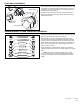

FV838 Rev. A 10/5/2023
Page 6
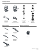
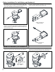
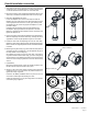
Diaphragm Kit
Manifold Stem
Volume
Control Ring
Orice
4. Place the valve head with the diaphragm kit back onto the valve
body. Ensure that both the strap wrench and locking ring are dry
for a better grip. Tighten the locking ring to its original position
using the supplied strap wrench by turning it clockwise.
Diaphragm Replacement and Cleaning (when necessary)
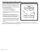
1. Turn off control stop using a flat head screwdriver turning
clockwise.Afterward,utilizethemanualoverridebuttontoush
wateroutoftheushvalve.
3B.Removetheexistingdiaphragmkitfromthemanifoldstem.If
theo-ringsshowsignsofwearordamage,replacethemwith
the new ones provided in the diaphragm repair kit.
Installanewdiaphragmkit(withmatchingowrate)intothe
valvebody,ensurethattheoriceispositionedoppositethe
control stop. Take care to align it properly.
NotethatunlesstheVolumeControlRingismissingorbroken,
there is no need to replace it.
3. Remove the existing diaphragm kit from the manifold stem.
Thoroughlywashthediaphragmandoriceusingwater.
Installthecleaneddiaphragmbackintothevalvebody,ensurethat
theoriceisfacingthecorrectorientation.Forthecorrectorice
orientation,Refertotheretrotinstallationinstructionsection.
Iftheissuepersistsaftercleaning,proceedtostep3B.
Donottodamageorenlargeorice.Doingsowillresultin
incorrectushrate.
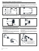
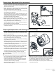
2.Before loosening the locking ring, ensure that both the strap
wrench and locking ring are completely dry. This will optimize
the grip of the strap wrench on the locking ring.
Use tape or a marker to mark the original position of the locking
ring in relation to the valve body.
Usingthesuppliedstrapwrench,loosenthelockingringonthe
valveheadbyturningitcounter-clockwise.Ifthestrapwrench
isunabletoloosenthelockingring,youmayusealargewrench
ontheatsofthelockingringtoloosenit.
5. Turn the control stop back on by turning counter-clockwise using
aatheadscrewdriver.
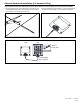
Locking
Ring
Control Stop
Manual override Button
Sensor Angle Adjustment (when necessary)
2.Before loosening the locking ring, ensure that both the strap
wrench and locking ring are completely dry. This will optimize
the grip of the strap wrench on the locking ring.
Use tape or a marker to mark the original position of the locking
ring in relation to the valve body.
Usingthesuppliedstrapwrench,loosenthelockingringonthe
valveheadbyturningitcounter-clockwise.Ifthestrapwrench
isunabletoloosenthelockingring,youmayusealargewrench
ontheatsofthelockingringtoloosenit.
1.Turn off control stop using a flat head screwdriver turning
clockwise.Afterward,utilizethemanualoverridebuttontoush
wateroutoftheushvalve.
3. Adjust the sensor angle by rotating the valve head
4.Before tightening the locking ring, ensure that both the strap
wrench and locking ring are completely dry. This will optimize
the grip of the strap wrench on the locking ring.
Usingthesuppliedstrapwrench,tightenthelockingringbackto
its original position by turning it clockwise.
5. Turn the control stop back on by turning counter-clockwise using
aatheadscrewdriver.