
Installation Guide

FV838 Rev. A 10/5/2023
Page 3
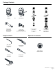
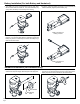
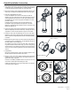
Flush Valve
Tailpiece
Locking Nut
Control Stop
O-Ring Groove
Snap Ring
Priortoattachingushvalvetailpiecetocontrolstop,inspectand
verify that the O-ring seal is located within the O-ring groove at
the tailpiece. Ensure that the locking nut and locking snap ring
are also present on the tailpiece.
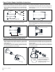
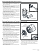
Flush Valve Installation
LubricateO-ringwithwaterifnecessaryandinsertushvalve
tailpiece into the control stop valve. Tighten locking nut using a
smooth jawed wrench.
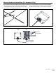
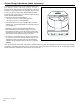
Vacuum Breaker
Tube Nut
Spud Nut
Slip Gasket
Rubber Gasket
Spud Escutcheon
-C-L-Indicator
Determine the length of vacuum breaker tube required to join the
ushvalveandxturespud,andcutifnecessary.
Slidethetubenut,spudnut,slipgasket,rubbergasketand
spud escutcheon over the vacuum breaker tube and insert tube
intoxturespud.Handtightentubenuttovalvebodyandhand
tightenspudnutontoxturespud.Adjustthevalveassemblyfor
plumb.Tightenxturespudnut,vacuumbreakertubenutand
locking nut with a wrench.
Adjust and plumb the valve assembly. Tighten all connections
with smooth jawed wrench and turn on water supply at the control
stop.
DO NOT cut vacuum breaker tube shorter than 6” below
the-C-L-indicatormark,asvacuumbreakermustbe6”above
thexture.ConsultplumbingCodes&Regulationsforspecic
details.
Vacuum Breaker & Flush Connection Installation