
Installation Guide

FV838 Rev. A 10/5/2023
Page 2
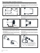
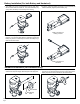
Sweat Solder Adapter Installation Instructions
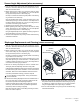
Control Stop Installation Instructions
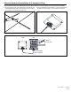
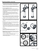
1.Measuredistancefromnishedwalltothecenterlineofthexture
spud.Ifnecessary,cutwatersupplypipe1-1/4”shorterthanthis
measurement.DeburrbychamferingO.D.andI.Dofendofwater
supply pipe.
NOTE: Before installation, turn o water supplies to existing xture and remove ushometer if replacing an existing device.
Finished
Wall
Water Supply Pipe
Center Line
of Fixture
Spud
1
1
⁄4“
Sweat Solder
Adapter
Set Screw
Chrome Cover Tube
Wall Escutcheon
Distance to
Measure
2. Slide threaded sweat solder adapter onto water supply pipe until
shoulder stops on end of pipe. Then sweat-solder the adapter to
water supply pipe.
3.Measuredistancefromnishedwalltorstthreadofsweatsolder
adapter.Ifnecessary,cutchromecovertubethislength.
4. Slide wall escutcheon over chrome cover tube and slide both
itemsoverwatersupplypipe.Presswallescutcheonushagainst
nishedwallandtightensetscrewwithhexwrench(supplied)to
secure it in place.
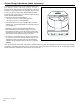
Usingaatheadscrewdriver,
turningcounterclockwise,ush
supply line by opening the
control stop. Turning clockwise
will close control stop.
2 Gallon
1.Installcontrolstopassemblybythreadingitontowatersupply
pipe and tightening with a smooth jawed wrench. Apply thread
sealing compound or pipe tape to male NPT thread on sweat
solder adapter only.
2. When all stop valves are properly connected to the water supply
line and water pressure is available open the control stop using a
atheadscrewdriverandturningthestopvalveadjustmentscrew
counterclockwise.
Prior to turning on main water supply line ensure all stop valves
areclosedotightbyusingaatheadscrewdriverandturning
the stop valve adjustment screw clockwise.
Allowthewatersupplylinetoushanydebrisorsedimentthat
may be present in the line. Close the control stop once the lines
arecompletelyushed.