
Installation Guide
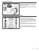

FV838 Rev. A 10/5/2023
Page 2
NOTE: The information in this manual is subject to change at any time without notice. Installations may
be performed at dierent times of construction by dierent individuals. For this reason, these instructions
should be left on-site with the facility or maintenance manager.
Important Safety Information
• Do not convert or modify this Zurn product. All warranties will be voided.
• All plumbing is to be installed in accordance with applicable codes and regulations.
• Watersupplylinesmustbesizedtoprovideanadequatevolumeofwaterforeachxture.
• Flush all water lines prior to making connections.
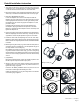
• Donotusepipesealantorplumbinggreaseonanyttingotherthanthecontrolstopinlet.
• Sensorunitsshouldnotbelocatedacrossfromeachotherorincloseproximitytohighlyreectivesurfaces.
• Controlstopshouldneverbeopenedtoallowowgreaterthanxtureiscapableofevacuating.Intheeventofvalvefailure,xture
mustbeabletohandleacontinuousow.
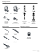
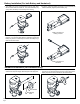
Prior to Installation
• Beforeinstallingyourushvalve,theitemslistedbelowshouldalreadybeinstalledon-site:
-Waterclosetorurinalxture
- Fixture carrier
- Drain line
- Water supply line
Specications
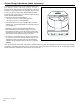
Sensor Range:
12” to 60” (adjustable)
Voltage:
3 VDC Paralleled [6 “AA” 1.5V Alkaline Cells] or with Optional Hardwired Kit (Supplied Separately)
Operating Water Pressure:
25 psi [172 kPa] (Running); 80 Psi [552 kPa] Max (Static)
Operating Temperature:
35°F to 104°F [2°C to 40°C]