
Install Instructions


FV343 Rev N 4/16/10
Page 3
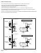
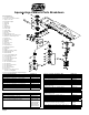
TOP OF FIXTURE
Ø
1 3/4
1 1/2 [
Ø
44
38]
HOLE
THROUGH
W ALL
11
1
2
[292]
3
1
8
[79]
4
3
4
[121]
1
3
8
[35]
10
1
8
[257]
Figure 1
Figure 2
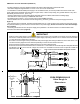
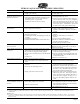
HW 6 Power Converter Installation (STEPS 1-4)
•The Zurn HW 6 Power Converter shall be installed in accordance with National/Local electrical codes.
• The HW 6 is shipped intergrated within a 4 11/16" X 4 11/16" X 2 1/8" electrical box.
• It is advisable to install the HW 6 power supply in an accessible location, as close as possible to the flush valves it will
power. Ideal location is behind an access panel, in a pipe chase, or above a drop ceiling. The greatest distance to any valve
shall ideally be less than 20 ft., (40 ft. max.).
• The Zurn-HW 6 Power Converter shall be direct wired with continuous 120VAC, 60Hz from the building supply.
• The HW 6 can be used to power up to 8 ZEMS-IS flush valves.
• Enclosed with each valve is 1 (one) connecting wire to power ZEMS-IS actuator.
• The wire shall be wire nut connected to the low voltage red (+) and blue (-) leads from the power supply as shown in
(Figure 1).
• The connecting wire is polarized. The black lead with white trace is (+) and connects to the red wire from the power supply.
The plain black lead is (-) and connects to the blue lead on the power supply. Do not cross wires as it will cause dam age
to the product!
• Connecting wire shall be run from the power supply to the predrilled 1-1/2" diameter holes in the finished wall for final
connection to the flush valves. (Figure 2)
IM PORTANT
1. Must use a Zurn power supply to ensure proper voltage for the system. Correct polarity is necessary to prevent damage to
the sensors. Check DC power level to ensure the power supply is providing a minimum of 7.4 volts DC. DC levels less than
7.4 volts will result in malfunction of the units.
2. Be certain to use the lengths of wire provided with each power supply when wiring the bathroom for the flush valves. The
connector and wire gauge have been selected specifically to match the Zurn Flushometer valve.
3. Each Flush Valve should be wired in parallel as shown in the wiring diagram below.
4. Ensure the access hole behind the flush valve is a minimum of 1-1/2” in diameter and located per Zurn templates #FV329
and #FV330. The plug end of the low voltage wire needs to be accessible at this hole when the plumber installs the
flushometer valve.
ZURN ZEMS6000AV-IS
Valve Rough In
Dim ensions
P6000-HW 6
120 VAC IN
7.6 VDC OUT
(+) BLACK W /
W HITE STRIPE
(-) BLACK
(+) BLACK W /
W HITE STRIPE
(-) BLACK
(+) RED
(-) BLUE
(-) BLACK
(+) BLACK W /
W HITE STRIPE
BLACK
(LINE)
W HITE
(NEUTRAL)
GREEN
(GROUND)
120
VAC
OPTIONAL -PC6
POW ER CONVERTER
(+) BLACK W /
W HITE STRIPE
(-) BLACK
RED
VDC
BLUE
GND
CAUTION:
RISK OF ELECTRIC SHOCK
DRY LOCATIO N USE ONLY
R
REGULATED POWER SUPPLY
PART NO : 200097001
MODEL NO : P6000-HW6
I/P : 120VAC/320mA@ Full load, 60Hz
O/P : +7.6.0VDCmin@2A load
DUTY CYCLE : 2sec
"On", 60sec "Off"
Delta Electronics (Thailand) Public Co.,Ltd.
7.6 VDC
OUT
BLACK
BLACK with
WHITE STRIPE
BLUE (-)
RED (+)
WHITE
BLACK
120 VAC
IN
P6000-HW6 W IRING
TO FAUCET
OR FLUSH VALVE
E323168
MADE IN THAILAND
C US
U
L
®
"Use Copper conductor only and
see details in instructioin manual"
"For Grounding Conductor, Use 18
AWG minim um"
WARNING:
To reduce risk of fire or electric
shock - Do not interconnect
output terminations.
Note: Connect to either the HW 6 or PC6 power converter.