
Installation Sheet

ZURN INDUSTRIES, LLC 5900 Elwin Buchanan Drive, Sanford, NC U.S.A. 27330, Ph. 1-800-997-3876, Fax 919-775-3541
In Canada: ZURN INDUSTRIES LIMITED 7900 Goreway Drive, Unit 10, Brampton, Ontario L6T 5W6, Ph. 905-405-8272, Fax 905-405-1292
Rev. H Date: 10/29/2018 C.N. No. SAN008373 Prod. | Dwg. No. CF1024
PAGE 2 OF 4
8. To adjust temperature limit stop (11), turn valve to desired hottest temperature, remove temperature
limit stop (11) turn clockwise and reinstall so that the white protrusion on cartridge is touching the
red protrusion on the temperature limit stop.
9.Afterallushingisdoneinstallshowerheadsandchecksystemforleaks.
10. Assemble external trim to valve.
•Hand tighten escutcheon nut (20) on valve.
•Remove tape from gasket (15) and adhere gasket (centered on the top half of the back of cover
plate (16)) so that 1/4 of the width of the gasket is sticking out beyond the back of the cover plate, see
Figure 2.
•Place cover plate over escutcheon (19) and fasten with screws (18).
•Install handle onto cartridge with handle pointed down. Tighten set screw.
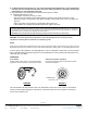
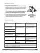
FIGURE 3FIGURE 2
Cover Gasket:
Position gasket in back side of cover with the adhesive
against the cover and the open end at bottom as shown.
TEMPERATURE
LIMIT STOP
Adjusting Temperature Limit Stop:
Lift and turn temperature limit stop clockwise to reduce
maximum temperature.
The ZURN TEMP-GARD III Pressure Balancing Shower Valve is equipped with an adjustable temperature limit stop. The temperature
limit stop device is to be used to limit the valve handle from being turned to undesired hot water discharge temperatures. To adjust the
temperaturelimitstop,seestep8oftheinstallationandreferencegure3.
IMPORTANT: Failure to adjust the temperature limit stop properly increases the chances for serious injury.
WARNING: This shower system may not protect the user from scalding when there is a failure of other
temperature controlling devices elsewhere in the plumbing system.
Notes:
When there is a shutoff valve installed after the control valve, there shall be stop and check valves on the inlets. This is to
eliminatehotandcoldcross-connectionintheeventthevalvehandleislefton.Specifysufx“-SC”forASSEapprovedchecks.
Ifvalveisgoingtobeinstalledin“ThinWallApplication”suchasaberglassorpanelwall,itisrecommended
thatanoptionalwallange(RK7300-WF)beused.Thiswallangeisusedtosandwichthewallbetweenthe
valve body and cover plate.
The main handle of the Temp-Gard III valve is for temperature control only. To turn valve on, the handle is
turned counterclockwise through the cold position, to the warm and then to the hot position. The range of
motion on the handle is 140
o
.
OPERATION: