
Installation Guide
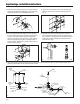
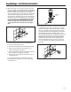


STEP NO. 1
Measure distance from finished wall to centerline of fixture spud;
cut water supply pipe 1-1/4" shorter than this mea sure ment.
Chamfer O.D. and I.D.
STEP NO. 3
Measure from finished wall to first thread of adapter for length of
chrome tube. Cut chrome tube this length ‘x’.
STEP NO. 4
Slide wall escutcheon over chrome tube and slide both chrome
tube and wall escutcheon over supply pipe pushing the wall
escutcheon all the way to the wall.
STEP NO. 2
Slide threaded adapter onto supply pipe until shoulder stops on
end of pipe. Then sweat-solder the adapter to water supply pipe.
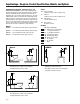
Sweat Solder Adaptor Installation Instructions
Important:
• All plumbing is to be installed according to state and local
codes and regulations.
• Water supply lines need to allow proper water flow for each
fixture.
• Flush all lines of any debris before making con nec tions.
• Do not use pipe sealant or plumbing grease on any fitting other
than the control stop inlet.
The AquaVantage
®
valve is designed to operate under various
water pressures with recommended range between 10 and 100
psi (69 to 689 kPa). Each Zurn valve is tested for proper perfor-
mance at the factory before being shipped. Consult the product
pages of the catalog for available flow options.
Most low consumption fixtures (1.6 gallon) require a minimum of
25 psi running pressure through the valve to obtain proper evacua-
tion. When installing your quality Zurn valve it is rec om mend ed
that to protect the polished finish you do not use a toothed
wrench. This will cause gouges and scratches on your valve.
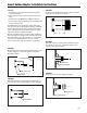
STEP NO. 5
Screw control stop onto water supply water adaptor.
C of FIXTURE SPUD
L
WATER SUPPLY PIPE
FINISHED WALL
CHROME TUBE
WALL ESCUTCHEON
‘X’
SWEAT ADAPTER
FINISHED WALL
CONTROL STOP
1
1
/
4
"
Page 3