
Installation Sheet


FV250 Rev. A 7/25/18 Page 3
Important:
• All plumbing is to be installed according to state and local
codes and regulations.
• Water supply lines need to allow proper water fl ow for each
fi xture.
• Flush all lines of any debris before making connections.
• Do not use pipe sealant or plumbing grease on any fi tting other
then the control stop inlet.
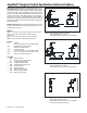
The Aquafl ush valve is designed to operate under various
water pressures with a recommended range between 10 and
100 psi (69 to 689 kPa). Each Zurn valve is tested for proper
performance at the factory before being shipped. Consult the
product pages of the catalog for available fl ow options.
Most low consumption fi xtures (1.28 and 1.6 gallon) require
a minimum of 25 psi running pressure through the valve to
obtain proper evacuation. Please be sure to consult fi xture
manufacturer on minimum running water supply requirements
for proper evacuation.
When installing your quality Zurn valve it is rec om mend ed that
to protect the polished fi nish you do not use a toothed wrench.
This will cause gouges and scratches on your valve.
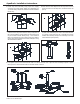
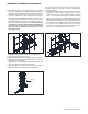
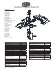
STEP NO. 1
Measure distance from fi nished wall to center line of fi xture spud;
cut water supply pipe 1-1/4” shorter than this mea sure ment.
Chamfer O.D. and I.D.
STEP NO. 3
Measure from fi nished wall to fi rst thread of adapter for length
of chrome tube. Cut chrome tube this length ‘x’.
STEP NO. 5
Screw control stop onto water supply water adaptor.
STEP NO. 4
Slide wall escutcheon over chrome tube and slide both chrome
tube and wall escutcheon over supply pipe pushing the wall
escutcheon all the way to the wall.
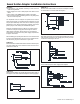
Sweat Solder Adaptor Installation Instructions
STEP NO. 2
Slide threaded adapter onto supply pipe until shoulder stops on
end of pipe. Then sweat-solder the adapter to water supply pipe.