
Installation Guide

Zurn Industries, LLC | Wilkins
1747 Commerce Way, Paso Robles, CA U.S.A. 93446 Ph. 855-663-9876, Fax 805-238-5766
In Canada | Zurn Industries Limited
3544 Nashua Drive, Mississauga, Ontario L4V 1L2 Ph. 905-405-8272, Fax 905-405-1292
www.zurn.com
Page 3 of 3
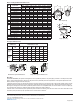
Valve Size
inches 2 2 1/2 3 4 6 8 10
mm 50 65 80 100 150 200 250
Suggested
Flow (GPM)
Max. Continuous 210 300 460 800 1800 3100 4900
Max Intermittent 260 375 600 1000 2250 4000 6150
Min. Continuous 15 20 30 50 115 200 300
Suggested
Flow
(Liters/sec)
Max. Continuous 13 19 29 50 113 195 309
Max. Intermittent 16.4 23 37 62 142 246 388
Min. Continuous 0.9 1.3 1.9 3.2 7.2 13 19
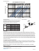
Flow Characteristics
0
1
10
100
10 1001000 10000
PRESSURE DROP (PSI)
FLOW (GPM)
BODY MINIMUM FRICTION LOSS
2" Globe
2" Angle
2-1/2" Globe
2-1/2" Angle
3" Globe
3" Angle
4" Globe & Angle
6" Globe
6" Angle
8" Globe
8" Angle
10" Globe
10" Angle
Flow Characteristics
Suggested flow calculations are based on flow through Schedule 40
Pipe. Maximum continuous flow is approx. 20 ft./sec (6.1 meters/
sec) & maximum surge is approx. 45 ft./sec (13.7 meters/sec).
Many factors should be considered in sizing pressure relief valves
including inlet pressure, outlet pressure and flow rates.
Specications
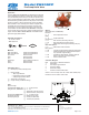
The Fire Pump Relief Valve shall be a single seated, line pressure operated, diaphragm actuated, pilot controlled globe or
angle valve. The valve shall seal by means of a corrosion-resistant seat and resilient, rectangular seat disc. These and other
parts shall be replaceable in the field; all such service and adjustments to be possible without removing the valve from the line.
The stem of the basic valve shall be guided top and bottom by integral bushings. The basic valve and its pilot control system
shall contain no packing glands or stuffing boxes. The diaphragm shall not be used as a seating surface nor shall pistons be
used as an operating medium. All internal and external ferrous surfaces shall be coated with a high quality, fusion epoxy coat-
ing. The pilot control system shall include a direct-acting, normally closed, spring-loaded, diaphragm actuated pilot valve with
the stem guided between the diaphragm assembly and seat disc. To ensure precise pressure relief, the appropriately rated pi-
lot valve shall be field adjustable within the pressure control range of the spring. The Fire Pump Relief Valve shall be a ZURN
WILKINS Model ZW205FP.
UL Installation Specication Requirements
UL installation specifications require the valve to be installed in accordance with the standard for installation of
sprinkler systems, NFPA 13, and with the standard for installation of stationary pumps for fire protection, NFPA 20.
The valve is to be inspected, tested and maintained in accordance with the standard for the inspection, Testing
and Maintenance of Water-Based Fire Protection Systems, NFPA 25.
Note: If the valve discharges to atmosphere adequate back pressure is very important, contact Zurn
Wilkins for assistance.
Typical Installation
FIRE PUMP
ZW209FP
ZW205FP
DIRECTION OF FLOW