
Installation Guide

Zurn Industries, LLC | Wilkins
1747 Commerce Way, Paso Robles, CA U.S.A. 93446 Ph. 855-663-9876, Fax 805-238-5766
In Canada | Zurn Industries Limited
3544 Nashua Drive, Mississauga, Ontario L4V 1L2 Ph. 905-405-8272, Fax 905-405-1292
www.zurn.com
Page 2 of 3
B
C
F
G
B
C
E
A
D
B
G
F
J
H
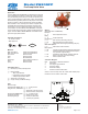
Operation
The Model ZW205FP pilot system is designed to sense upstream pressure. The pilot piping contains a normally closed, direct
acting, spring loaded pilot valve, which may be preset to the particular pressure requirements of the system (Pilots are avail-
able in pressure ranges from 50 to 300 psi.).
If upstream pressure does not exceed the preset on the pilot spring, the pilot and the main valve remain tightly closed. Should
upstream pressure exceed the set point of the pilot, both the pilot and main valve will open, relieving the excess pressure by
allowing flow through the valve. When upstream pressure returns to acceptable limits, the reverse action occurs. The pilot pip-
ing provides quick opening for pressure relief and slow closing for surge protection.
A check valve on the inlet of the pilot system will prevent water from draining from the main valve cover when used with a verti-
cal turbine pump to ensure proper operation of the control valve at all times.
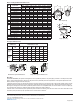
Globe and Angle Main Valve Dimensions
Angle Style Body
Globe Style Body
PILOT SYSTEM
DIMENSIONS
VALVE SIZE inches (mm)
DIM
2"
(50)
2-1/2"
(65)
3"
(80)
4"
(100)
6"
(150)
8"
(200)
10"
(250)
Full Port
Body
X 8 1/2 8 1/2 9 1/2 12 13 14 17 1/2
Y 3 1/2 4 4 1/2 6 8 10 12
Z 9 9 9 1/2 10 11 1/2 13 14 1/2
Angle
Body
X 10 10 10 11 7/8 12 1/4 15 1/2 17 1/2
Y 5 1/4 5 1/4 5 1/4 6 8 10 11 7/8
Z 9 3/4 9 1/2 9 1/2 11 1/4 13 3/8 15 1/4 18
Pilot System Dimensions
Angle Pilot System Dimensions
Y
Z
X
Z
Y
X
INLET
INLET
Globe Pilot System Dimensions
INLET
X
Z
Y
DIM FULL PORT
2 (50) 2 1/2 (65) 3 (80) 4 (100) 6 (150) 8 (200) 10 (250)
A
Threaded 9 7/16 11 12 1/2
Class 150 Flange 9 3/8 11 12 15 20 25 3/8 29 3/4
Class 300 Flange 10 11 5/8 13 1/4 15 5/8 21 26 7/16 31 1/8
Grooved 9 11 12 1/2 15 20 25 3/8 29 3/4
B Diameter 6 3/4 8 9 3/16 11 11/16 15 3/4 20 1/8 23 11/16
C Max
.
6 3/16 7 3/8 8 10 3/16 12 5/16 15 9/16 17 5/8
D
Threaded/Grooved 1 3/4 2 1/8 2 9/16 3 7/16 5 5 5 13/16
Class 150 Flange 3 3 1/2 3 3/4 4 1/2 5 1/2 6 3/4 8
Class 300 Flange 3 1/4 3 3/4 4 1/8 5 6 1/4 7 1/2 8 3/4
E NPT Body Tap 3/8 1/2 1/2 3/4 3/4 1 1
F NPT Cvr. Plug Tap 1/2 1/2 1/2 3/4 3/4 1 1
G NPT Cover Tap 3/8 1/2 1/2 3/4 3/4 1 1
H
Threaded 4 3/4 5 1/2 6 1/4
Class 150 Flange 4 3/4 5 1/2 6 7 1/2 10 12 11/16 14 7/8
Class 300 Flange 5 6 6 7/16 8 10 1/2 13 1/4 15 9/16
Grooved 4 3/4 5 1/2 6 7 1/2 10 12 11/16 14 7/8
J
Threaded 3 1/4 4 4 1/2
Class 150 Flange 3 1/4 4 4 5 6 8 8 5/8
Class 300 Flange 3 1/2 4 5/16 4 7/16 5 5/16 6 1/2 8 1/2 9 5 /16
Grooved 3 1/4 4 4 1/4 5 6 8 8 5/8
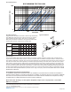
Valve Stem Internal Thread 10-32 10-32 1/4-20 1/4-20 1/4-20 3/8-16 3/8-16
Stem Travel (in) 3/4 7/8 1 1 3/16 1 3/4 2 3/8 2 13/16
Approx. Wt. (lbs) 36 55 70 130 240 440 720