
Install Instructions
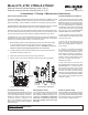

SEAT ASSEMBLY
SEAL RING
O-RING
(BOLT)
SEAL RETAINER
WASHER
BOLT
CHECK HANDLE
O-RING (SEAT)
Maintenance Instructions
3
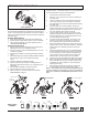
RELIEF VALVE
ASSEMBLY
SERVICING CHECK VALVES
A ratchet wrench, 11/16" deep socket, and a 4" long extension
are recommended for removing check assemblies.
1. Close inlet and outlet shut-off valves.
2. Open No. 2, No. 3 and No. 4 test cocks to release pres-
sure from valve.
3. Loosen & remove the grooved coupling around the ac-
cess cover. Remove cover. Place towel or cardboard
over relief valve port in body to prevent parts from falling
into relief valve.
4. To service only the #1 check assembly, remove the
6 bolts, washers and o-rings from the back of the #1 check
assembly. Separate the retainer and the seal ring from
the check assembly and proceed to step #8.
5. To service both checks or the #2 check, the #1 check
assembly must rst be removed. Remove the 4 nuts and
washers retaining the #1 check assembly. Remove the
#1 check assembly from the body.
6. To remove the #2 check assembly, remove the 7 nuts,
washers and the #2 check retaining ring. Grasp the
check assembly by the stem and remove from valve.
7. Remove all 6 bolts, washers and o-rings from the check
assembly (See "Check Assembly" illustration). Separate
retainer from check assembly to expose seal ring for
inspection.
8. Inspect the rubber seal ring for cuts or embedded debris.
If the reverse side of the seal ring is unused, it is possible
to invert the seal ring. This would be considered a tem-
porary solution to xing a fouled check and should be
replaced with a new seal ring as soon as possible.
9. Inspect valve cavity and seating areas. Remove any debris.
10. Reverse the above procedures to reinstall check assem-
blies. Lubricate seat o-rings to hold them in place while
reinstalling seat. Place washers on studs and tighten
retaining nuts evenly.
11. Remove towel or cardboard covering from relief valve
port. Reinstall access cover and grooved coupling.
NOTE: If any portion of the seat assembly is damaged or missing
or if the seat sealing rib is damaged in any way, do not attempt to
eld repair it. Contact your local WILKINS representative for assis-
tance.
All Model 475 Reduced Pressure Principle Backow Preventers must
be inspected and maintained by licensed personnel at least once
a year or more frequently as specied by local codes. Replace-
ment of worn or damaged parts must only be made with genuine
"WILKINS" parts.
GENERAL MAINTENANCE
1. Clean all parts thoroughly with water after disassembly.
2. Carefully inspect rubber seal rings and o-rings for damage.
3. Test unit after reassembly for proper operation (refer to
"TESTING PROCEDURES").
SERVICING RELIEF VALVE
1. Remove relief valve cover bolts and cover. Gently pull on
diaphragm to remove the cartridge assembly.
2. Inspect seal ring for cuts and embedded debris. Turn over
or replace if required.
3. Disassemble cartridge by unscrewing relief valve retainer
screw.
4. Inspect diaphragm and o-rings for damage. Replace required
parts and apply a light coat of lubricant to plunger
o-ring.
5. Carefully reassemble cartridge assembly.
6. Inspect relief valve seat for wear on seating surface. If
damaged, replace seat and seat o-ring. Install spring over
seat guides.
7. Insert cartridge assembly into relief valve body.
8. Replace relief valve cover and cover bolts.
9. Place the device in service and test per "TESTING
PROCEDURES" on page 2.
CHECK ASSEMBLY
COVER
BOLTS
COVER
UPPER
PLUNGER
DIAPHRAGM
PLUNGER
O-RING
LOWER
PLUNGER
SEAL
RING
WASHERS
RETAINER
SCREW
SEAT
SPRING
BODY
SEAT
O-RING
a company
®
®
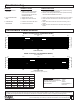
PLATE RETAINER
#2 CHECK ASSEMBLY
#2 CHECK ASSEMBLY
WIRE RETAINER
#1 CHECK
ASSEMBLY
FIGURE 1 FIGURE 2 FIGURE 3