
User's Guide
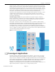
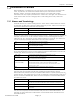


Table Of Contents
- CHAPTER 1 Introduction
- CHAPTER 2 First Time Installation
- 2
- 2.1 Overview
- 2.2 System Setup
- 2.3 Configuration Step by Step
- 2.3.1 Log into ZoneDAS
- 2.3.2 Set System Time
- 2.3.3 Ensure that RF Inputs are Within Range (0 ~ 24 dBm)
- 2.3.4 Configure BU Parameters
- 2.3.5 Loading a Pre-Set Configuration with a Config File
- 2.3.6 Checking RF Activity from the BU Screen
- 2.3.7 Mount Each RU
- 2.3.8 Configure RU Parameters
- 2.3.9 Turn Service On
- 2.3.10 Fill in Descriptive Information
- 2.3.11 Set Central Management
- 2.3.12 Save Settings
- 2.3.13 Backup Configurations
- CHAPTER 3 The Web Configurator
- CHAPTER 4 Home
- Chapter 5 Setting
- Chapter 6 Fault
- CHAPTER 7 System
- CHAPTER 8 Maintenance

Chapter 1: Introduction
ZoneDAS User Guide Page | 9
SD Port
SD Port
RF Slot A
RF Slot D
RF Slot B
RF Slot C
Table 3 RU System Parts
LEDs (Lights)
The following table describes the LED signals on the RU.
Table 4 RU LEDs
LED COLOR STATUS DESCRIPTION
PWR (Power) Green On The system is powered on
Off The DC power is off.
SYS (System) Red On
There is a hardware failure, such as device overheat or abnormal fan
speed.
Off The system is functioning normally.
Cable Red On The cable signal loss currently exceeds the threshold.
Off The signal is below the threshold.
Active Green On The inserted RU-RF module is powered on.
Off The inserted RU-RF module is not ready.
ALM (Alarm) Red On The system detects an operational error.
Off The inserted RU-RF module is functioning normally.
RF Module Placement
Each Remote Unit has an RJ45 port on one side and LED lights on the opposite side. The
following illustration shows where RF modules A, B, C and D are placed in relation to the port
and lights.
Figure 5 Remote Unit RF Modules
SYSTEM PART DESCRIPTION
RU-MB
The RU Motherboard (RU-MB) provides the platform upon which up to 4 RU-RF
modules may reside. Each RU-
RF slot is labelled A, B, C or D, to match the RF slots on
the BU. The system is able to power the RU-MB and each RU-RF independently.
These devices also provide LEDs signals independently. Three LEDs are used to
provide signals for RU-MB. The next table explains what their signals mean.
RU-RF
The RU’s Radio Frequency modules (RU-RF) are the devices that actually broadcast
RF signals to users’ cell phones. Each RU-RF comes with its own antenna (external
antenna models excluded), and each RU has up to four RF modules, referred to as
RU-RFA to RU-RFD. The letter after RU-RF represents the slot in which the RF module is
installed.
Note: The frequency used by the RF module in each RU must match that of the RF
module in the BU. For example, if you use a Band 1 RF module for BU-RFA, then you
must also use a Band 1 RF module for RU-RFA.