
User's Guide
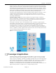
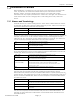


Table Of Contents
- CHAPTER 1 Introduction
- CHAPTER 2 First Time Installation
- 2
- 2.1 Overview
- 2.2 System Setup
- 2.3 Configuration Step by Step
- 2.3.1 Log into ZoneDAS
- 2.3.2 Set System Time
- 2.3.3 Ensure that RF Inputs are Within Range (0 ~ 24 dBm)
- 2.3.4 Configure BU Parameters
- 2.3.5 Loading a Pre-Set Configuration with a Config File
- 2.3.6 Checking RF Activity from the BU Screen
- 2.3.7 Mount Each RU
- 2.3.8 Configure RU Parameters
- 2.3.9 Turn Service On
- 2.3.10 Fill in Descriptive Information
- 2.3.11 Set Central Management
- 2.3.12 Save Settings
- 2.3.13 Backup Configurations
- CHAPTER 3 The Web Configurator
- CHAPTER 4 Home
- Chapter 5 Setting
- Chapter 6 Fault
- CHAPTER 7 System
- CHAPTER 8 Maintenance

Chapter 1: Introduction
ZoneDAS User Guide Page | 7
1.3.2 BU (Base Unit)
The Base Unit is the command center for the entire system. Every device on the system is
controlled by or through the Base Unit. To a large degree, the Base Unit’s LED indicators also
reflect the state of the entire system. These LEDs and ports are located on the BU’s Front
Panel. The figure below shows the Front Panel and its different parts.
Figure 3 BU Front Panel
The following table describes the parts that are labelled in the figure above.
Table 1 BU System Parts
SYSTEM PART DESCRIPTION
Fan Module
The BU’s fan module provides active cooling for the entire BU, which can operate
safely for just a few minutes fan free. The fan module is hot-swappable and user
replaceable. See the Hardware Installation Guide for replacement instructions.
BU-MB
The BU’s Motherboard (BU-MB) is the user’s gateway to controlling everything in
ZoneDAS. To access the Web Configurator, connect a computer to the MGMT port
via a CAT5 cable. To access the Command Line Interface (used by the vendor
only), connect it to the Serial Port with a serial cable.
BU-RF (A to D)
A is the left most slot
D is the right most slot
This is where the BU houses its collection of Radio Frequency (RF) modules. Each BU
has 1 to 4 of these modules, and each module provides one RF port.
To connect the
BU to a signal source, install an RF module into an RF slot and connect a coaxial
cable from the module’s RF port to the coaxial outlet at the signal source. The base
station can be a picocell, femtocell, LTE RRU (Remote Radio Unit), etc. See the
Hardware Installation Guide on how to properly install a BU-RF module.
Note: The frequency used by the RF module in each RU must match the one used
by the corresponding RF module in the BU. For example, if you use a Band 1 RF
module for BU-RFA, then you must also use a Band 1 RF module for RU-RFA.
BU-SD
(ports labeled RU1 to RU8)
This is where the BU houses its Signal Distribution (SD) modules. Each BU comes with
one SD module and has room for one other.
Each SD module comes with 4 SD ports,
and each SD port can connect one RU or Extender. To connect an RU or Extender,
simply pick an SD port (install a second SD module if the first is full) and connect a
CAT5e cable from the RU’s SD port (or the Extender’s Extender port) to the BU’s SD
port. The BU supports the IEEE 802.3af PoE standard and can supply power to any
connected RU (only RUs, not Extenders). For instructions on installing BU-SD modules,
please see the Hardware Installation Guide.
Note: See the Hardware Installation Guide for information on the proper installation
of BU-RF and BU-SD modules.
LEDs (Lights)
Most ports/modules on the BU come with their own set of LED signal lights. These include the
MGMT port, each BU-RF, each BU-SD, and the BU-MB. These LEDs provide important
information, and the following table explains what the different lights mean.