WARNING! Electronic Emission Notices Federal Communications Commission (FCC) Statement This equipment has been tested and found to comply with the limits for a Class B digital device, pursuant to Part 15 of FCC Rules. These limits are designed to provide reasonable protection against harmful interference in a residential installation.
AMD A75ITX series motherboard Table of Contents Motherboard Specifications-------------------------------------------------------------------- 4 Motherboard Layout------------------------------------------------------------------------------ 6 Hardware Installation----------------------------------------------------------------------------- 9 Safety Instructions------------------------------------------------------------------------------ 9 Preparing the motherboard----------------------------------------
Table of Contents SYS Fan Control Mode------------------------------------------------------------------- 28 Exit Menu----------------------------------------------------------------------------------------- 28 Save Changes and Exit------------------------------------------------------------------- 29 Discard Changes and Exit--------------------------------------------------------------- 29 Save Changes and Reset---------------------------------------------------------------- 29 Discard Changes and Reset--
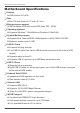
AMD A75ITX series motherboard Motherboard Specifications q Chipset v AMD Hudson D3 (A75) q Size v Mini ITX form factor of 6.7 inch x 6.7 inch q Microprocessor support v AMD A-Series APUs with socket FM2 (max TDP: 140W) q Operating systems: v Supports Windows 7 32bit/64bit and Windows 8 32bit/64bit q System Memory support v Supports Dual Channel DDR3 1866(depends on APU)/1600/1333/1066 v Maximum memory size: 16 GB q USB 2.0 Ports v Supports hot plug and play v Two USB 2.
Motherboard Specifications q Onboard Audio v 8 channel High Definition Audio (including one optical SPDIF output port) v All DACs support 192k/96k/48k/44.1kHz sample rate v One SPDIF-out header on board q PCI Express Support v Supports PCI Express 2.
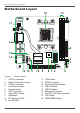
AMD A75ITX series motherboard Motherboard Layout 19 K/B USB 18 1 121 121 CPUFAN PWR2 17 1 SW1 DIMM1 DIMM3 DVI/HDMI 1.5V 1.5V PWR1 LAN/USB 16 LAN/USB 2 AUDIO . FP_USB3_1 CN6 1. 2. 3. 4. 5. 6. 7. 8. 9. 10. 6 120 240 120 240 SYSFAN FP1 MINI_PCIE1 CN5 51 JP1 PCIEX16 10 9 8 7 6 FP2 52 2 13 12 11 Figure 1. SATA3 SATA4 SATA1 SATA2 . 14 .
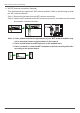
Rear Panel Figure 2: Backpanel connectors 9 1 2 3 8 7 4 2 6 5 1. PS2 Keyboard/Mouse Port 2. USB 3.0 Ports 3. Clear CMOS Button 4. HDMI Port 5. Optical SPDIF Output 6. Port Blue Green Pink Black Orange 2-Channel Line-In Line-Out Mic In --- 4-Channel Line-In Front Speaker Out Mic In -Rear Speaker Out 6-Channel Line-In Front Speaker Out Mic In Center/Subwoofer Rear Speaker Out 8-Channel Side Speaker Out Front Speaker Out Mic In Center/Subwoofer Rear Speaker Out 7.
AMD A75ITX series motherboard 9. WiFi/BT antenna connectors (Optional) This motherboard can support two WiFi antenna modules. Refer to the following to install the WiFi antenna modules. Step 1. Remove the red caps from the WiFi antenna connectors. Step 2. Install the WiFi antennas to the WiFi antenna connectors, and make sure the screws are rotated in clockwise direction. 121 121 . . . 1.5V 1.5V 120 240 120 240 Note: 1.
Hardware Installation Hardware Installation This section will guide you through the installation of the motherboard.
AMD A75ITX series motherboard Installing the CPU Be very careful when handling the CPU. Make sure not to bend or break any pins on the back. Hold the processor only by the edges and do not touch the bottom of the processor. Use the following procedure to install the CPU onto the motherboard. 1. Please turn off the power and unplug the power cord before installing the CPU. Pull the lever up and away from the socket until it is at a 90 degree angle to the motherboard. 2. Look for the gold arrow on the CPU.
Hardware Installation Installing Memory Modules This motherboard accommodates two memory modules. It can support two 240-pin DDR3 1866/1600/1333/1066. The total memory capacity is 8 GB. You must install at least one module in any of the two slots. Refer to the following recommendations to install the memory modules. 121 121 . . . 1.5V 1.5V DIMM1 DIMM3 120 240 120 240 Note that a memory module has a notch, so it can only fit in one direction.
AMD A75ITX series motherboard Installing the Motherboard The sequence of installing the motherboard into the chassis depends on the chassis you are using and if you are replacing an existing motherboard or working with an empty chassis. Determine if it would be easier to make all the connections prior to this step or to secure the motherboard and then make all the connections. It is normally easier to secure the motherboard first.
Hardware Installation Connecting Cables and Setting Switches This section takes you through all the connectors and switch settings necessary on the motherboard.
AMD A75ITX series motherboard 24-pin ATX Power Connector PWR1 is the main power supply connector. Make sure that the power supply cable and pins are properly aligned with the connector on the motherboard. Firmly plug the power supply cable into the connector and make sure it is secure. PWR1-Pin Definition 121 121 12 PWR1 24 . . . 1.5V 1.5V 120 240 120 Pin Signal Pin Signal 1 +3.3V 13 +3.3V 2 +3.
Hardware Installation USB Headers This motherboard contains six USB 3.0 ports that are exposed on the rear panel of the chassis (Figure 2). The motherboard also contains one 10-pin internal USB 2.0 header and one 20-pin USB 3.0 connector onboard. The onboard headers are optional. Note: Secure the bracket to either the front or rear panel of your chassis (not all chassis are equipped with the front panel option). 121 121 1.5V 1.5V . . .
AMD A75ITX series motherboard FP Audio Header The audio connector supports HD audio standard and provides two kinds of audio output choices: the Front Audio, the Rear Audio. The front Audio supports re-tasking function. 121 121 . . .
Hardware Installation Front Panel Header The front panel header on this motherboard is one connector used to connect the following four cables: q PWR LED Attach the front panel power LED cable to these two pins of the connector. The Power LED indicates the system’s status. q PWR SW Attach the power button cable from the case to these two pins. Pressing the power button on the front panel turns the system on and off rather than using the power supply button.
AMD A75ITX series motherboard Connecting Serial ATA Cables (optional) The Serial ATA III connector is used to connect the Serial ATA III device to the motherboard. These connectors support the thin Serial ATA III cables for primary storage devices. The current Serial ATA III interface allows up to 6 Gb/s data transfer rate. There are four serial ATA connectors on the motherboard. CPU FAN Connector 121 121 GND +12V 1.5V SATA4 120 SATA2 240 SATA3 120 SATA1 . . . 1.
Hardware Installation Expansion Slots The motherboard contains two expansion slots: one PCI Express x16 slot and one Mini PCI Express slot. 121 121 . . . 1.5V 1.5V 120 240 120 240 MINI_PCIE1 PCIEX16 Mini PCI Express Slot-MINI_PCIE1 There is one Mini PCIe slot, reserved for the WiFi Module. PCI Express x16 Slot-PCIEX16 There is one PCIe x16 slot reserved for graphics card. It is fully compliant with PCI Express 2.0 specification.
AMD A75ITX series motherboard Jumper Settings This chapter explains how to configure the motherboard’s hardware. Before using your computer, make sure all jumpers and DRAM modules are set correctly. Refer to this chapter whenever in doubt. JP1-Clear CMOS JP1 Selection 1 1-2* Normal* 1 2-3 Clear CMOS Close Open * = Default setting. If you want to clear the system configuration, use the JP1 (Clear CMOS Jumper) to clear data. Notice: 1. Be sure to save the CMOS setting when exit the CMOS. 2.
Hardware Installation Configuring the BIOS This section discusses how to change the system settings through the BIOS Setup menus. Detailed descriptions of the BIOS parameters are also provided. Enter BIOS Setup The BIOS is the communication bridge between hardware and software. Correctly setting the BIOS parameters is critical to maintain optimal system performance. Use the following procedure to verify/change BIOS settings. 1. Power on the computer., 2.
AMD A75ITX series motherboard q Memory Information Displays the auto-detected memory information. q System Language Choose the system default language. q System Date/Time Allows you to set the system date/time. X-Setting Menu The X-Setting menu items show the settings of CPU, memory and so on.
Configuring the BIOS Advanced Menu The Advanced menu items allow you to change the settings for the CPU and other system devices. Press to display the configuration options: OnBoard Device Configuration The items allow you to configure onboard device, including HD Audio, LAN and so on. q PS2 Keyboard/Mouse Swap When set to [Enabled], the PS2 port can support either keyboard or mouse. When set to [Disabled], the PS2 port can support keyboard only. q Serial Port Enable or disable serial port.
AMD A75ITX series motherboard q Restore on AC Power Loss This item allows you to configure how the system board responds to a power failure. q Wake On Lan Use this item to enable or disable wake on lan. q Wake system with Fixed Time Use this item to enable or disable wake system with fixed time. CPU Configuration The items in this menu show the CPU-related information that the BIOS automatically detects.
Configuring the BIOS q XHCI Hand-off Allows you to enable support for operating systems without an XHCI hand-off feature. q EHCI Hand-Off Allows you to enable support for operating systems without an EHCI hand-off feature. q USB transfer time-out Allows you to set USB transfer time-out. q Device reset time-out Allows you to set device reset time-out. q Device power-up delay Allows you to set device power-up delay. Chipset Menu The chipset menu items allow you to change the advanced chipset settings.
AMD A75ITX series motherboard Boot Menu The Boot menu items allow you to change the system boot options. Press to display the configuration options: Boot Settings Configuration The items allow you to configure Boot settings. Press To display the configuration options: q Setup Prompt Timeout Use this item to set number of seconds to wait for setup activation key. q Bootup NumLock State Use this item to select the keyboard NumLock state: [On] or [Off].
Configuring the BIOS q Other PCI device ROM priority Use this item to set other PCI device ROM priority. Security Menu The security menu items allow you to change the system security settings. Press to display the configuration options: Administrator Password Select this item to set Setup Administrator Password. User Password Select this item to set the user password. To set an Administrator/User Password: 1. Select the item [Administrator/User Password] and press . 2.
AMD A75ITX series motherboard PC Health Menu Select PC Health from the BIOS Setup Utility menu to display the System menu. SYS Fan Control Mode This item allows you to set the system fan control mode. Exit Menu The exit menu items allow you to load the option or failsafe default values for the BIOS items, and save or discard your changes to the BIOS items.
Configuring the BIOS Save Changes and Exit Select this item and press to save the changes that you have made in the BIOS Setup and exit the BIOS Setup. When the diolog box [Save configuration and exit?] appears, select [Yes] to save and exit, or select [No] to return to the main menu Discard Changes and Exit Select this option only if you do not want to save the changes that you have made to the setup program.
AMD A75ITX series motherboard Launch EFI Shell from filesystem device Use this item to launch EFI Shell application (Shellx64.efi) from one of the available filesystem devices. Flash Update Procedure The program EFUDOS.exe is included in the driver disk (X:\Utility\EFUDOS.exe). Please follow the recommended procedure to update the flash BIOS, as listed below. (X: your driver disk letter). 1. Create a DOS-bootable floppy diskette.
Configuring the BIOS Installing Drivers and Software Note: 1. It is important to remember that before installing the driver disk that is shipped in the kit, you need to load your operating system. The motherboard supports Windows 7 32bit/64bit and Windows 8 32bit/64bit. 2. We reserve the right to update the driver version presented in the manual. The driver installation pictures shown in this section are for reference only. The kit comes with a DVD that contains utility drivers and additional software.
AMD A75ITX series motherboard 32
Installing Drivers and Software 3. Left-click Realtek HD Audio Driver, and follow the instructions below to install the sound driver.
AMD A75ITX series motherboard 4. Left-click Realtek Network Driver, and follow the instructions below to install the network driver.
Installing Drivers and Software 5. Left-click Intel Wireless Driver, and follow the instructions below to install the wireless driver.
AMD A75ITX series motherboard 36
Installing Drivers and Software 6. Left-click Bluetooth Driver, and follow the instructions below to install the bluetooth driver.
AMD A75ITX series motherboard 7. At last, you can enter Device Manager interface that provides information about the hardware devices on this motherboard, and check if the installation is finished.
Installing Drivers and Software Realtek HD Audio Driver Setup Getting Started After Realtek HD Audio Driver being installed (insert the driver disk and follow the on-screen instructions), “Realtek HD Audio Manager” icon will show in System tray as below. Double click the icon and the control panel will appear: Sound Effect After clicking on the “Sound Effect” tab, 3 sections “Environment”, “Equalizer” and “Karaoke” are available for selection.
AMD A75ITX series motherboard Equalizer Selection The Equalizer section allows you to create your own preferred settings by utilizing this tool. In standard 10 bands of equalizer, ranging from 100Hz to 16KHz are available: Frequently Used Equalizer Setting Realtek recognizes the needs that you might have. By leveraging our long experience at audio field, Realtek HD Audio Sound Manager provides you certain optimized equalizer settings that are frequently used for your quick enjoyment.
Installing Drivers and Software Mixer Realtek HD Audio Sound Manager integrates Microsoft’s “Volume Control” functions into the Mixer page. This gives you the advantage to you to create your favorite sound effect in one single tool. Playback control Mute You may choose to mute single or multiple volume controls or to completely mute sound output. Tool √ Show the following volume control This is to let you freely decide which volume control items to be displayed, total 13 items to be chosen.
AMD A75ITX series motherboard With this function, you will be able to have an audio chat with your friends via headphone (stream 1 from front panel) while still have music (stream 2 from back panel) playing. At any given period, you can have maximum 2 streams operating simultaneously. Recording control Mute You may choose to mute single or multiple volume controls or to completely mute sound input.
Installing Drivers and Software Audio I/O Realtek HD Audio Manager frees you from default speaker settings. Different from before, for each jack, they are not limited to perform certain functions. Instead, now each jack is able to be chosen to perform either output (i.e. playback) function or input (i.e. Recording) function, we call this “Retasking”. Audio I/O aims to help you setting jacks as you wish.
AMD A75ITX series motherboard Speaker Configuration Step 1: Plug in the device in any available jack. Step 2: Dialogue “Connected device” will pop up for your selection. Please select the device you are trying to plug in. * If the device is being plugged into the correct jack, you will be able to find the icon beside the jack changed to the one that is same as your device.
Installing Drivers and Software Connector Settings Click to access connector settings √ Mute rear panel when front headphone plugged in Once this option is checked, when front headphone is plugged, the music that is playing from the back panel, will be stopped. √ Disable front panel jack detection (option) Did not find any function on front panel jacks? Please check if front jacks on your system are so-called AC’97 jacks. If so, please check this item to disable front panel jack detection.
AMD A75ITX series motherboard √ Output Sampling Rate - 44.1KHz: This is recommended while playing CD 48KHz: This is recommended while playing DVD or Dolby 96KHz: This is recommended while playing DVD-Audio 192KHz: This is recommended while playing HD Audio √ Output Source - Output digital audio source: The digital audio format (such as .wav, .mp3, .midi etc) will come out through S/PDIF-Out.
Installing Drivers and Software Microphone This page is designed to provide you better microphone/recording quality. Below picture indicates both “Noise Suppression” & “Acoustic Echo Cancellation” are both enabled. Noise Suppression If you feel that the background noise, especially the sound generated from the fan inside PC, is too loud? Try “Noise Suppression”, which allows you to cut off and suppress disturbing noise.
AMD A75ITX series motherboard 3D Audio Demo The section “3D Audio Demo” grants you another possibility to enjoy your sound. The Audio Demo allows you to listen to sound in an extraordinary way. Information This section provides information about your current system audio device.
SATA RAID User Manual SATA RAID User Manual Setting up the BIOS 1. 2. Setting your computer, then press to enter BIOS SETUP UTILITY. Use the arrow key to select Advanced menu. When enter the Advanced menu, select the Item “IDE/SATA Configuration”. 3. Press to display IDE/SATA Configuration, then select the item “OnChip SATA Type”.
AMD A75ITX series motherboard 4. Press and enable the option “RAID”. 5. 6. 7. Enable the disks that you want to use as RAID disks. Press F10 to save the configuration and exit. The PC reboots. Enter the RAID BIOS Setup by pressing F10 when prompted, and proceed to set up the RAID BIOS as described in the next Section.
SATA RAID User Manual Entering the RAID BIOS Setup 1. After rebooting your computer, wait until you see the RAID software prompting you to press . 2. Option ROM Utility (c) 2009 Advanced Micro Devices, Inc.-Main Menu window appears. Creating a RAID set 1. In Main Menu, select <2> to enter LD View Menu, and press to enter LD Define Menu. a. In the RAID Mode field, use the space bar to select a RAID Mode.
AMD A75ITX series motherboard 2. In Drives Assignments menu, use the space bar to select , and press . 3. Enter the LD name. 4. Modify Array Capacity, and press to save the modification. When the setup is finished, press to exit the RAID interface. After the PC reboots, the RAID controller will display the ready RAID.
SATA RAID User Manual Deleting a RAID set 1. In Main Menu, select <3> to enter Delete LD Menu, and select the RAID you want to delete. 2. Press to delete the RAID, or press any other key to abort.
AMD A75ITX series motherboard Installing the RAID Drivers 1. After you complete the RAID BIOS setup, boot from the windows disk. The Windows Setup program starts. 2. Press F6 and wait a few moments for the Windows Setup screen to appear. 3. a. Specify the AMD drivers. Insert the floppy that has the RAID driver, and select the SCSI Adapter, then press .
SATA RAID User Manual b. When the window below display, press to use the driver on floppy. c. Press to continue the windows setup.
AMD A75ITX series motherboard 56 291-MA234-00