
Install Instructions
FORM 2316
3
the furnace or air handler. It is often the most convenient location
and closest to power, the HVAC unit controls and the zone dampers
when typically located at or near the plenum.
The H32 panel case is made of sturdy ABS plastic and can be
mounted to any flat surface. It is recommended that the panel be
mounted to a wall or return plenum and NOT on the furnace or
plenum where it will be in contact with the excessive temperatures.
The panel can be located in an attic space or in an enclosed cabinet of
a rooftop unit. Insure the panel is not in direct exposure to the
elements.
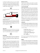
The cover easily removes from the case by pulling firmly and
separating the cover from the case exposing the circuit board. There
are 4 key-hole mounting points in each corner of the case. The case
has openings in the rear of the case as well as the side for all wiring.
Wiring can come from the back as well as the side in order to make a
neat installation.
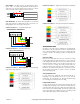
OPERATION
The H32 can be controlled by conventional single stage or heat pump
thermostats. Each thermostat can then call for heating, cooling or the
fan. This panel can control single stage gas-oil-electric heating and
cooling, two stage heating and cooling and most heat pumps. This
panel can control two stage/speed and dual/fossil fuel heat pumps.
When a call for either heating or cooling is made the panel will open
the damper(s) to the zone(s) calling, close the damper(s) to those
zones not calling, activate the appropriate controls for heating or
cooling, whichever is being called and not accept any calls for the
opposite mode.
Any calls for the opposite mode will be locked out until the initial
mode is either satisfied or a period of time has elapsed that is
sufficient for the first mode to satisfy, a maximum of 20 minutes. A
unique sequence determines the time the unit has been running or
needs to continue to run in order to adequately provide conditioning
for each mode. If a particular mode has already been calling for 20
minutes or longer and an opposite call comes in the H32 will
immediately drop the mode, enter the purge mode in order to
dissipate the conditioned air into the zones calling before switching
over to provide the new conditioning call to its zones.
When using the H32 to control two stage heating, the second stage is
controlled based upon time after the first stage call from the
thermostat. When any zone calls the panel’s built-in timer begins and
after the set period of time elapses the H32 will also activate the W2
for second stage heating. The Second Stage Timer is adjustable
between 5 to 25 minutes after the first stage calls. Once the second
stage is on, it will continue to run until the first stage is satisfied.
Once all zone thermostats are satisfied for heating and cooling, the
H32 can now accept Fan calls allowing Continuous Air
Circulation(CAC) in those zones where the thermostat’s Fan Switch is
set to ON. These zone dampers will be Open, while the dampers to
the zones where the Fan Switch is set to AUTO will be CLOSED.
When all zone thermostats are satisfied for both Heating and Cooling,
and all Fan switches are set to AUTO position, the HVAC unit will be
off and all zone dampers will return to a normally open position.
Once a zone calls for heating, cooling or fan, the dampers to the
calling zones remain open and the dampers to the zones not calling
will close.
Set-Up for Various HVAC Equipment
The H32 is factory set for conventional heating and cooling operation.
The panel only needs to be configured when using with an electric
furnace or heat pumps.
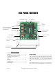
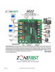
The panel configuration is done by setting the DIP switches in the top
right of the panel. Other functions come by wiring for specific
applications. Below is shown the most typical settings. Review each
function for you application.
SYSTEM – G/E OR HP This switch sets the HVAC Output operation.
In G/E the Y1 operates as first stage cooling only. In HP position Y1
makes as the compressor call for both heating and cooling.
HP Type – CONV or FF – This switch is used to determine the
equipment output when the System switch is set to HP , this switch
determines if the output will be for a conventional heat pump with
electric back-up heat or fossil (dual) fuel mode.
FAN IN HEAT – YES or NO – This switch will activates the Fan on a
call for Heat in the Yes position. In Off, the heating unit must activate
the fan when the heat is called.
FAN PURGE – YES or NO – This switch determine if the Fan is kept
on during the Purge Mode, after the end of each heat or cool call.
STAT RV – O or B – When using HP type thermostats this determines
if the O or B terminal is wired to the W/OB terminal on each
thermostat to determine if the call if for Heat (B) or Cool (O).
TSTAT – HC-HP Switch determines if conventional Heat/Cool
thermostats or Heat Pump thermostats are being used for ALL zones.
A conventional HC stat would have separate W and Y output for
heating and cooling calls. A HP thermostat uses Y for both a heat and
cool call and the O or B is used to determine whether the call is for
Cooling (O) or Heating (B).
EM HEAT –
This switch sets any heat call to call for the Emergency
Heat. The Red EM HEAT LED on the panel will light only when this
switch is ON. This is used when there is no EH switch on the
thermostats.
TEST – This
switch accelerates the panel timings in order to provide a
quick checkout of all of the functions without having to wait the full
time for each sequence.
One of the many features of the DIP switches is if at any time the
equipment is changed from single stage to heat pump or vice versa
the thermostats do not need to be changed with the equipment
change. Changing the DIP switch settings is all that is needed.
Le
aving Air and Outdoor Air Sensor
The Leaving Air Sensor, Model ZPS, is a remote sensor that is located
in the supply air duct to sense the Leaving Air temperature of the
HVAC Unit. The ZPS is a high limit protection for the heating and a
low limit protection for the cooling. The ZPS protects the equipment
in low air flow situations as well as when by-pass air is being directed
back into the return air duct.
© Copyright Trolex Corporation & ZoneFirst