Non-Interpretive 12-Lead ECG Monitoring September 2006 9650-1215-01 Rev.
The issue date or revision level for this Operator’s Guide is shown on the front cover. ZOLL is a registered trademark and E Series is a trademark of ZOLL Medical Corporation. © 2006 by ZOLL Medical Corporation. All rights reserved.
Product Description NON-INTERPRETIVE 12-LEAD ECG MONITORING General Information ECG leads are a defibrillation-protected Type CF patient connection. Product Description ZOLL E Series™ with the non-interpretive 12-lead option provides simultaneous 12-lead ECG acquisition, storage, and transmission.
Non-Interpretive 12-Lead ECG Monitoring WARNINGS • Before use, carefully read the E Series Operator's Guide and these operating instructions. • Always ensure that the patient is kept motionless during 12-lead ECG signal acquisition. Use of the device to acquire ECG signals from moving or shaking patients may produce erroneous 12-lead data. • Excessive body hair or wet, sweaty skin may interfere with electrode adhesion. Remove the hair and/or moisture from the area where the electrode is to be attached.
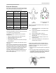
Electrode Placement Electrode Placement Depending on local usage, ECG lead wires are marked with certain labels. Refer to the following table for labels and color codes for the different lead sets.
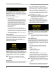
Non-Interpretive 12-Lead ECG Monitoring 3. Locate the second intercostal space on the patient’s right side, lateral to and just below the Angle of Louis. 4. Move your finger down two more intercostal spaces to the fourth intercostal space which is the V1 position. Note: When placing electrodes on female patients, always place leads V3-V6 under the breast rather than on the breast. second waveform prior to entering 12-lead monitor mode, press the Wave 2 softkey.
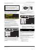
12-Lead ECG Data Transmission Keypad on top, right side of unit. CAUTION Transmission of 12-lead ECG data via cellular phones can be less reliable than transmission via landline connections. A strong signal and stationary transmission improves the transmission’s success rate. Follow the directions provided with your cellular phone.
Non-Interpretive 12-Lead ECG Monitoring • 0.05 - 150 Hz frequency 4x3 channel printout: • Pressing Retry displays the Transmission screen, so that transmission can be performed again. Pressing Return displays the main 12-lead screen. If 30 seconds elapse and a softkey is not pressed, the main 12-lead screen will be displayed.
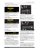
12-Lead ECG Data Transmission leads preconfigured for that particular custom group. (See the E Series Configuration Guide for more information.) 37 1$0( 37 ,' Press the Lead Grp softkey to scroll through and highlight the different Lead Group selections for three channel printing. Press the Enter softkey to save the highlighted Lead Group and return to the 12 Lead Monitor menu. Dial Type Setting Selecting the Dial Type setting allows you to select either Tone or Pulse dialing.
Non-Interpretive 12-Lead ECG Monitoring Press the Return softkey to save the highlighted age and return to the Patient Information screen. If you want to return to the Patient Information screen without saving the highlighted age, press the Cancel softkey.
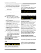
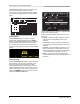
12-Lead ECG Data Transmission 12-Lead ECG Waveforms 4x3 Format By default, the 4x3 format prints 10 seconds of 12-lead ECG data in four staggered 2.5 second segments. Each 2.5 second segment displays the ECG reading for one set of three leads (see the following figure). You can configure the report for either standard or Cabrera print formats. 1 mV calibration pulses are printed at the beginning of the report for each data channel. You can also configure the E Series unit to print 5, 7.
Non-Interpretive 12-Lead ECG Monitoring 2x6 Format (Fax Report Only) The 2x6 Format prints all 12-lead ECG data recorded during the first 5 second interval. The 2x6 format inhibits printing of the lead II rhythm strip normally printed on the fax page. The stripchart always prints in the 4x3 format. Fax the 2x6 format immediately after acquisition. The 2x6 fax image is not stored in the patient records. You can, however, reproduce patient data in 4x3 format at a later time.
Daily Operational Verification Daily Operational Verification In addition to the routine unit testing recommended in the E Series Operator’s Guide, perform these steps daily to ensure proper operation of the E Series non-interpretive 12-lead option. You will need either a 12-lead simulator or a volunteer “patient”. 1. Connect the V-lead cable to the 12-lead cable. 2. Connect the lead wires of the 12-lead cable and V-leads to the patient or simulator.
Non-Interpretive 12-Lead ECG Monitoring Troubleshooting The troubleshooting section is intended to help you identify and correct problems that arise during operation. If trouble persists after consulting this information, contact the ZOLL Technical Service Department. ZOLL Technical Service Department (USA) Phone: (800) 348-9011 (UK) Phone: +44-192-584-6400 (Other locations) Contact your local ZOLL distributor.
Troubleshooting Symptom FAX ERROR message is displayed. Recommended Action • A dialing problem other than a busy line, no carrier, or no connection occurred. • The E Series automatically re-transmits until the transmission is successful or the E Series operator presses the Abort softkey. FAX HANGUP message is displayed. • Receiving phone is not receiving transmission.
Non-Interpretive 12-Lead ECG Monitoring (This page intentionally left blank.
Troubleshooting APPENDIX A: Modem and Phone Setup The E Series with non-interpretive 12-lead option may include a modem for transmitting 12-lead ECG information to remote locations via landline or cellular phone. This section describes how to connect your E Series for phone transmission. Modem • When included, the E Series with non-interpretive 12-lead option ships with a cellular-ready PC card modem • (U.S.A. units only) installed in the front PCMCIA slot on top of the unit.
Non-Interpretive 12-Lead ECG Monitoring • For connection to a Motorola 3-Watt "Bag Phone" or vehicle-mounted phone, ZOLL recommends using the included landline cable along with Motorola's Cellular Connection, Model S1936D. This device is also known as a dial tone generator and is used to interface the RJ-11 landline connector with the 3-Watt cellular phone. The Motorola Model S1936D, along with support for vehicle-mounted phones, is available through AirDesk, Inc. in Warminster, PA: www.airdeskwireless.
Phone Company Requests Phone Company Requests If the telephone company requests information about the equipment connected to their lines, inform them of: • The telephone number to which the device is connected. • The ringer equivalence number (REN) which is found on the FCC sticker attached to the modem. The REN determines how many devices may be connected to the same telephone line. If too many devices are attached, they may not ring properly.
Non-Interpretive 12-Lead ECG Monitoring Shielded Cables The use of any cable other than the shielded type will allow your system to emit more radio frequency interference than the FCC limits, thereby increasing the likelihood of interference. Therefore, in order to comply with the FCC regulations, it is necessary that you use good quality shielded cables with your installation.