INTELLIGENT SUMP HIGH VOLUME WiFi SUMP PUMP BY MODEL #STBS700 Zoeller® is a registered trademark of Zoeller Co. All Rights Reserved. Español p. 17 BasementSentry.com ATTACH YOUR RECEIPT HERE Purchase Date Questions, problems, missing parts? Before returning to your retailer, call our customer service department at 1-800-584-8089, 7:30 a.m. - 5:00 p.m., EST, Monday - Friday. 1 © 2020. All rights reserved.
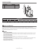
PACKAGE CONTENTS DESCRIPTION QUANTITY A Pump 1 B Controller 1 C Dual float 1 A B C E G SPECIFICATIONS MODEL HP DISCHARGE AMPS STBS700 3/4 1-1/2 in. 9.0 PERFORMANCE IN GALLONS PER MINUTE 0 FT. 5 FT. 10 FT. 15 FT. 20 FT. 80 72 62 50 35 SAFETY INFORMATION Please read and understand this entire manual before attempting to assemble, operate, or install the product. NOTE: Pumps with the “UL” Mark and pumps with the “US” mark are tested to UL Standard UL778.
SAFETY INFORMATION (CONTINUED) WARNING • • • • • • • ELECTRICAL SHOCK ALERT. Before installing this product, have the electrical circuit checked by an electrician to ensure proper grounding. All electrical installations must conform to the National Electric Code and all local codes. ELECTRICAL SHOCK ALERT. Connect this product to a properly-grounded 115 volt circuit equipped with a Ground Fault Circuit Interrupter (GFCI) device.
CONNECTING THE STBS700 PUMP TO THE CONTROLLER By connecting the STBS700 pump to the Basement Sentry app using the built-in WIFI, the user can set up free alert messages via email and mobile app “push” notifications. In addition, the user can verify the STBS700 pump readiness, remotely silence alarms, reset the unit, configure settings, and modify how notifications are sent. Other visual information such as pump status are available through the web and app interfaces.
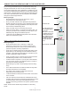
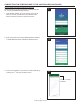
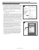
CONNECTING THE STBS700 PUMP TO THE CONTROLLER (CONTINUED) Use the Mobile App (iOS and Android) (Continued) 1 These instructions provide an overview of what the app will do. You may find additional steps needed. 1. O pen the app and sign in to your account, If you do not have an account, you will need to click the link at the bottom of the home screen to create an account. 2. O pen your profile to set up any additional phone numbers or email addresses where notifications should be sent. 2 3.
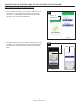
CONNECTING THE STBS700 PUMP TO THE CONTROLLER (CONTINUED) Use the Mobile App (iOS and Android) (Continued) 4. O nce a location is created, you will need to add a device. To add a device, choose the desired location name and then touch the “+” to start adding a device. Allow access to the camera so you can scan the data matrix. 4 5. T he app will ask you to scan the data matrix QR code on the controller.
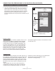
CONNECTING THE STBS700 PUMP TO THE CONTROLLER (CONTINUED) Use the Mobile App (iOS and Android) (Continued) 6. W hen the captive screen opens, use the WiFi Scan button to find the WiFi network you want the controller to use, select it from the list provided at the bottom of the screen (you may need to scroll), and type the password in the field. The Z Control® LED should be solid within a minute indicating successful connection to the router and the Z Control® Cloud.
CONNECTING THE STBS700 PUMP TO THE CONTROLLER (CONTINUED) Option 2 - Use your mobile device or computer to connect directly to the Basement Sentry controller Instead of using a mobile device and the Z Control® app, you can also use your mobile device or computer to directly connect to the controller. • Any VPNs or other network controls may need to be temporarily turned off during setup. Before you begin: • Create a free account at zcontrolcloud.com.
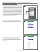
CONNECTING THE STBS700 PUMP TO THE CONTROLLER (CONTINUED) Connecting with your mobile device or computer (Continued) 2. S tanding near the controller, use your phone, tablet, or computer to look for the Basement Sentry controller SSID in your WiFi settings. It will look similar to “ZCTL_SSUMP_XXXX” where “xxxx” is the first 4 digits of your controller device ID. Select this, and be sure your device displays a check mark or similar indicator that you are connected to the controller local network.
CONNECTING THE STBS700 PUMP TO THE CONTROLLER (CONTINUED) Connecting with your mobile device or computer (Continued) 4. O nce the controller LED is solid, log in to your account (or create one) at zcontrolcloud.com. Choose the Add New Device button next to the location you want the controller (see Figure D). Follow the directions to add your controller by either auto-detect or entering the Device I.D. When successful, a Basement Sentry product tile will appear in your account.
STBS700 PUMP LED, BUTTON, ALARM, AND CONTROLLER BEHAVIORS Z Control LED and Power LED Alarm Behaviors Alarm Silence Button Communications Power LED is on when AC power is present. Input LED on solid. Alarm triple beeps continuously. Z Control LED LED is solid when connected to router and Basement Sentry app. LED is off when STBS700 controller is in AP mode.* LED blinks when WIFI setup is in process. LED blinks faster if STBS700 controller is attempting to reconnect to a known router.
PREPARATION Estimated Installation Time: 15 minutes Materials required for assembly: Sump basin, inlet piping, discharge piping (PVC, poly pipe or galvanized steel), check valve, and 2-step PVC glue system (primer and sealer). This pump is designed to be installed in a sump basin for removing clear drain water and will usually pass small particles suspended in water.
SUMP PUMP INSTALLATION 1. C AUTION: For your safety, turn off the electrical power at the service entrance to avoid any possible electrical shock hazards. Before installing the pump in the sump pit, be sure to unplug the pump from the outlet. 1 115 V GFCI outlet Disconnect the existing pump from the power source. Disconnect or cut the main discharge pipe and separate the primary sump pump from the discharge pipe. Remove the pump from the sump basin.
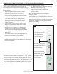
SUMP PUMP INSTALLATION (CONTINUED) 4. Connect the discharge pipe, fittings, and check valve (not provided) to pump discharge. The discharge pipe should be the same size as the discharge of pump (1-1/2-in) or larger. 4 Discharge pipe and fittings A check valve must be installed in the discharge pipe to keep water from draining back into the sump basin when it is not operating. Check valve NOTE: Make sure there is enough room in the basin for the float to move freely.
SUMP PUMP INSTALLATION (CONTINUED) 6. B. P osition second float float at desired ‘on level’ on the discharge pipe. 6B Right-angle Mounting Bracket Discharge Pipe On level 6. C. Attach mounting bracket to the discharge pipe as shown, using hose clamp (included). 6C WARNING: DO NOT install high water float in direct line of incoming water or close to the vent hole. Hose Clamp Discharge Pipe 7. M ake sure your hands are dry and you are not standing in water.
WARRANTY This product is warranted for three years from the date of purchase. Subject to the conditions hereinafter set forth, the manufacturer will repair or replace to the original consumer any portion of the product which proves defective due to defective materials or workmanship. To obtain warranty service, contact the dealer from whom the product was purchased. The manufacturer retains the sole right and option to determine whether to repair or replace defective equipment, parts, or components.
SUMIDERO INTELIGENTE BOMBA DE SUMIDERO DE GRAN VOLUMEN CON WiFi BY MODELO #STBS700 Zoeller® es una marca registrada de Zoeller Co. Todos derechos reservados. BasementSentry.com ADJUNTE SU RECIBO AQUÍ Fecha de compra ¿Preguntas, problemas, partes faltantes? Antes de acudir al minorista, llame a nuestro departamento de servicio al cliente al 1-800-584-8089, de lunes a viernes de 7:30 a.m. a 5:00 p.m., EST. 1 © 2020. Todos los derechos reservados.
CONTENIDO DEL PAQUETE DESCRIPCIÓN CANTIDAD A Bomba de 12 V con junta tórica 1 B Controlador 1 C Flotador doble 1 A B C MODELO HP DESCARGA STBS700 3/4 1-1/2” ESPECIFICACIONES RENDIMIENTO EN GALONES POR MINUTO AMPERIOS 0 PIES 5 PIES 10 PIES 15 PIES 20 PIES 9.0 80 72 62 50 35 INFORMACIÓN DE SEGURIDAD Lea y comprenda completamente este manual antes de intentar ensamblar, usar o instalar el producto.
INFORMACIÓN DE SEGURIDAD (CONTINUACIÓN) ADVERTENCIA • • • • • • • ALERTA DE DESCARGA ELÉCTRICA. Antes de instalar este producto, haga que un electricista revise su circuito para asegurarse de que la puesta a tierra sea adecuada. Todas las instalaciones eléctricas deben cumplir con el Código Nacional de Electricidad (NEC, por sus siglas en inglés) y con todos los códigos locales. ALERTA DE DESCARGA ELÉCTRICA.
CONECTAR LA BOMBA STBS700 AL CONTROLADOR Al conectar la bomba STBS700 a la aplicación Basement Sentry mediante el WiFi integrado, el usuario puede configurar mensajes de alerta gratuitos por correo electrónico y notificaciones “push” de la aplicación móvil. Además, el usuario puede verificar la disponibilidad de la bomba STBS700, silenciar alarmas de manera remota, restablecer la unidad, ajustar las configuraciones y modificar la forma de envío de las notificaciones.
CONECTAR LA BOMBA STBS700 AL CONTROLADOR (CONTINUACIÓN) Utilizar la aplicación móvil (iOS y Android) (continuación) 1 Estas instrucciones brindan una descripción general de lo que hará la aplicación. Es posible que se necesiten pasos adicionales. 1. A bra la aplicación e inicie sesión en su cuenta. Si no tiene una cuenta, deberá hacer clic en el enlace en la parte inferior de la pantalla de inicio para crear una. 2.
CONECTAR LA BOMBA STBS700 AL CONTROLADOR (CONTINUACIÓN) Utilizar la aplicación móvil (iOS y Android) (continuación) 4. U na vez que se haya creado una ubicación, necesitará agregar un dispositivo. Para agregar un dispositivo, elija el nombre de la ubicación deseada y luego toque el signo “+” para comenzar a agregar un dispositivo. Permita acceso a la cámara así puede escanear la matriz de datos. 5. L a aplicación le pedirá que escanee el código QR de la matriz de datos en el controlador.
CONECTAR LA BOMBA STBS700 AL CONTROLADOR (CONTINUACIÓN) Utilizar la aplicación móvil (iOS y Android) (continuación) 6. C uando se abra la pantalla capacitiva, utilice el botón “WiFi Scan” (Escanear WiFi) para buscar la red WiFi que quiera que el controlador use, selecciónela de la lista que se proporciona en la parte inferior de la pantalla (es posible que deba desplazarse) y escriba la contraseña en el campo.
CONECTAR LA BOMBA STBS700 AL CONTROLADOR (CONTINUACIÓN) Opción 2 - Utilice su dispositivo móvil o computadora para conectarse al controlador Basement Sentry directamente En lugar de utilizar un dispositivo móvil y la aplicación Z Control®, también puede utilizar su dispositivo móvil o computadora para conectarse al controlador directamente. • Puede ser necesario apagar temporalmente cualquier VPN u otros controles de red durante la configuración.
CONECTAR LA BOMBA STBS700 AL CONTROLADOR (CONTINUACIÓN) Conectarse con su dispositivo móvil o computadora (continuación) 2. P arado cerca del controlador, use su teléfono, tableta o computadora para buscar el SSID del controlador Basement Sentry en la configuración de su WiFi. Aparecerá como “ZCTL_SSUMP_XXXX”, donde “xxxx” son los primeros 4 dígitos del ID de su dispositivo controlador.
CONECTAR LA BOMBA STBS700 AL CONTROLADOR (CONTINUACIÓN) Conectarse con su dispositivo móvil o computadora (continuación) 4. U na vez que el LED del controlador quede fijo, inicie sesión en su cuenta (o cree una) en zcontrolcloud.com. Elija el botón “Add New Device” (Agregar dispositivo nuevo) junto a la ubicación donde quiere al controlador (ver figura D). Siga las instrucciones para agregar su controlador, ya sea a través de la detección automática o el ingreso del ID del dispositivo.
COMPORTAMIENTO DE LOS LED DE LA BOMBA STBS700, BOTÓN, ALARMA Y CONTROLADOR Comportamiento LED de alimentación de los LED del Alarma Z-Control y las alarmas LED de Z Control El LED de alimentación se enciende cuando existe alimentación CA. Botón de silencio Presionar/Soltar Silencia las alarmas. El LED de la alarma se queda encendido (o parpadea) hasta que se reinicie el controlador STBS700.
PREPARACIÓN Tiempo estimado de instalación: 15 minutos Materiales necesarios para en ensamblaje: recipiente para sumidero, tubería de entrada, tubería de descarga (PVC, polietileno o acero galvanizado), válvula de retención y sistema de adhesivo para PVC de 2 pasos (cebado y sellado). Esta bomba está diseñada para instalarse en un recipiente para sumidero para eliminar agua de desagüe limpia y, por lo general, dejará pasar pequeña partículas suspendidas en el agua.
INSTALACIÓN DE BOMBA DE SUMIDERO 1. P RECAUCIÓN: Para su seguridad, desconecte la alimentación eléctrica en la entrada de servicio para evitar posibles riesgos de descarga eléctrica. Antes de instalar la bomba en el pozo del sumidero, asegúrese de desconectar la bomba de la toma de corriente. 1 115 V GFCI outlet Desconecte la bomba existente de la fuente de energía. Desconecte o corte la tubería de descarga principal y separe la bomba de sumidero principal de la tubería de descarga.
INSTALACIÓN DE BOMBA DE SUMIDERO (CONTINUACIÓN) 4. Conecte la tubería de descarga, los conectores y la válvula de retención (no provista) a la descarga de la bomba. La tubería de descarga debe tener el mismo tamaño que la descarga de la bomba, (1 1/2”) o mayor.
INSTALACIÓN DE BOMBA DE SUMIDERO (CONTINUACIÓN) 6. B. P onga el flotador secundario en el “nivel de encendido” deseado en la tubería de descarga. 6B Soporte de montaje en ángulo recto Tubería de descarga Nivel de encendido 6. C. F ije un soporte de montaje en el tubo de descarga como se muestra, utilizando una abrazadera de manguera (incluida). 6C ADVERTENCIA: NO instale el flotador de nivel de agua alto en línea directa del agua entrante o cerca del orificio de ventilación.
GARANTÍA Este producto se garantiza por un período de tres años a partir de la fecha de compra. Sujeto a las condiciones indicadas a continuación, el fabricante se compromete a reparar o reemplazar al consumidor original cualquier parte del producto que resulte defectuosa debido a defectos de materiales o mano de obra. Para obtener el servicio de garantía, póngase en contacto con el distribuidor al que le compró el producto.