
Install Instructions

ALARM PANEL for OIL SMART
®
& OIL GUARD
®
SYSTEMS
INSTALLATION IN STRUC TIONS
SECTION: 6.10.105
FM2192
0111
Supersedes
0609
Notice to Installer: Instructions must remain with installation.
© Copyright 2011 Zoeller Co. All rights reserved.
Maintenance
1. Plastic switch case and metal sensor leads must be kept clean,
free of corrosion, mud, soap. Clean switch every four months or
as often as environmental conditions dictate.
2. Clean with oil base product like kerosene, solvent or WD40. Do
not use soap.
1. All installations must be in accordance with the National Electrical
Code, and any other applicable state and local electrical
requirements.
2. Do not remove ground pin. Severe electrical shock could occur.
3. Check with local codes for proper installation.
1. The switch and pump are not rated for explosive environments.
This product is intended for hydraulic oils only.
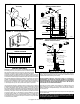
Installation Instructions for 1 1/2" pipe.
1. Review fi gures 1,2,3,4, and 5.
2. Attach Oil Smart
®
Liquid Alarm Switch to Quick Mount Bracket using
#10 screws and nuts provided (See Figure 1).
3. Snap bracket onto discharge pipe or fl oat tree (See Figure 1).
4. Install Oil Smart
®
Liquid Alarm Switch at high water level 10" above
normal pump "on" level.
5. Place hose clamp on pipe under Quick Mount Bracket (See Figure 1)
for reference location of the Oil Smart
®
Liquid Alarm Switch.
6. For easy maintenance, snap Quick Mount Bracket assembly off and
on pipe using the hose clamp as a guide.
7. Mount Oil Smart
®
Liquid Alarm Switch clear of inlet water at least 1"
to 2" away from any metallic material.
8. Mount Alarm Panel and connect to a separate branch GFCI circuit
(See Figure 3 or 4).
Installation Instructions other than 1 1/2" pipe.
1. Use the universal PVC bracket and clamp provided.
2. Insert hose clamp through top of bracket (See Figure 2).
3. Mount Oil Smart
®
Liquid Alarm Switch to universal bracket using #10
screws and nuts provided.
4. Install Oil Smart
®
Liquid Alarm Switch at high water level 10" above
normal pump "on" level using clamp provided.
5. Mount Oil Smart
®
Liquid Alarm Switch clear of inlet water at least 1"
to 2" away from any metallic material.
6. Mount Alarm Panel and connect to a separate branch GFCI circuit
(See Figure 3 or 4).
Installation instructions for mounting to basin wall.
Reference FM2364 or FM2104.
For remote Supervisory Control and Data Acquisition
(SCADA) (See Figure 5).
TB1:
1. Water - location #8. Normally open
2. Com- location #9.
3. Oil - location #10. Normally open
4. Alarm - location #11. Normally open
Oil Smart
®
Liquid Alarm Switch Operation
Oil Smart
®
Liquid Alarm Switch detects high liquid levels and
differentiates the presence of oil and water. Activates a red light, audible
alarm and oil (yellow) or water (white) indicator light.
Alarm Mode 1 (oil present): If oil is present in the water as the level
rises to the Oil Smart
®
Liquid Alarm Switch, the red and yellow lights
will turn on and the alarm will sound.
Alarm Mode 2 (high water): If no oil is present as the level rises to the
Oil Smart
®
Liquid Alarm Switch, the red and white lights will turn on
and the alarm will sound.
Testing Oil Smart
®
Liquid Alarm Switch
A. Plug alarm panel into electrical outlet (115V).
B. Fill paper cup with water.
C. Submerge optical sensor in water (metal probe exposed to air)
D. Touch a wet paper towel or wet rag to the metal probe. Water
indicator light (white), audible and alarm light will turn on. Repeat
test using oil.
Product information presented
here re fl ects con di tions at time
of publication. Consult factory
re gard ing dis crep an cies or
in con sis ten cies.
MAIL TO: P.O. BOX 16347 • Louisville, KY 40256-0347
SHIP TO: 3649 Cane Run Road • Louisville, KY 40211-1961
(502) 778-2731 • 1 (800) 928-PUMP • FAX (502) 774-3624
visit our web site:
www.zoeller.com
Your Peace of Mind is Our Top Priority
™