
Sizing Guide

GRINDER PUMP SIZING AND SELECTION WORKSHEET
To begin, ll in the shaded areas on the front side. A calculator and additional sheet of paper may be required.
FIGURE B
PUMP CAPACITY based on total Fixture Units*
STEP #1 Determine the type and quantity of each
plumbing xture. Multiply each by its
xture unit values in gure “A”.
Sum these values ______
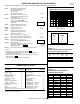
Determine GPM from gure “B”. ______GPM (1)
STEP #2 Refer to Figure “C”. Based on the System’s
discharge piping size, Determine the minimum
GPM Listed for that size. ______GPM (2)
STEP #3 Select the greater of the two GPM values in
#1 & #2. This is your Design GPM. If
greater than maximum GPM listed in gure, “B”,
contact factory. ______GPM (3)
STEP #4 Multiply each pipe tting by its equivalent
length value shown in gure “D” and sum. ______Ft. (4)
STEP #5 Total pipe length from front side ______Ft. (5)
STEP #6 Add #4 & #5. [(4) + (5) = (6)] ______Ft. (6)
STEP #7 Divide #6 by 100 and multiply it by the
associated friction value from Figure “E”.
This is the total Friction Head. ______Ft. (7)
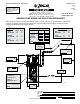
STEP #8 Determine static head in Ft., as shown on front
side, from minimum water level to the discharge point. ______Ft. (8)
STEP #9 Sewer Pressure, if any, expressed in feet (PSI x 2.31). ______Ft. (9)
STEP #10 Add #7, #8, & #9. [(7) + (8) + (9) = (10)].
This is the system’s Total Dynamic Head. (TDH) ______Ft. (10)
STEP #11 Select the Grinder Pump:
Select grinder pump from FM1478 (820) or FM1232 (840).
Base selection on design values, #3 & #10 . ______(Part No.)
Required voltage source ______(Volt/Phase)
STEP #12 Select type of control, basin size, and type of assembly from FM1232.
Final Notes:
1) Consult Factory in any application where TDH is less than 5’ #10 .
2) Consult Factory in those applications where the performance requirement exceeds
the capability of the Model 840 Grinder.
2) Pump must be capable of providing the minimum required GPM for pipe size, Figure “C”,
at the calculated TDH #10 .
3) Pump’s lock valve must be greater than system’s highest point.
FIGURE C*
FIGURE E*
FRICTION HEAD IN FEET PER 100’ OF
SCHEDULE 40 PLASTIC PIPE
1¼” 1½” 2”
GPM Plastic Plastic Plastic
10 1.45 0.68 0.20
12 2.03 0.96 0.28
15 3.06 1.45 0.43
18 4.29 2.03 0.60
21 5.75 2.71 0.80
25 7.89 3.73 1.10
30 11.1 5.22 1.55
35 14.7 6.95 2.06
40 --- 8.90 2.64
45 --- 11.1 3.28
50 --- 13.45 3.99
60 --- --- 5.59
70 --- --- 7.44
TOTAL FIXTURE UNIT VALUES
Fixture Fixture
Description Unit Value
Bathtub, 1-1/2” trap 2
Bathtub, 2” trap 3
Bidet, 1-1/2” trap 3
Dental unit or cuspidor 1
Drinking fountain 1
Dishwasher, domestic 2
Kitchen sink 2
Kitchen sink with disposal 3
Lavatory, 1-1/2” trap 1
Lavatory, barber/beautician 2
laundry tray 2
Shower 2
Shower, group (per head) 3
Fixture Fixture
Description Unit Value
Sink, service type 3
Sink, scullery 4
Sink, surgeons 3
Swimming pool (per 100 gallons) 1
Urinal 4**
Washing machine 2
Water closet 3**
Water softener 4
Unlisted xture, 1-1/4” trap 2
Unlisted xture, 1-1/2” trap 3
Unlisted xture, 2” trap 4
Unlisted xture, 2-1/2” trap 5
Unlisted xture, 3” trap 6
6**
FIGURE A
PLUMBING FIXTURE UNIT VALUES*
Pipe Minimum
Size GPM
1¼” 10
1½” 13
2” 21
PUMP CAPACITY - GALLONS PER MINUTE
Bathroom group consisting of lavatory, bathtub or shower, and water closet
* Graph data is taken form ASPE Handbook, Uniform Plumbing Code, Cameron Hydraulic Data and Plastic Pipe Institute.
** Add 4 xture units for each ush valve xture
© Copyright 2015 Zoeller
®
Co. All rights reserved.
10 20 30 40 50 60
70 80 90 100
200
70
60
50
40
30
20
FIGURE D*
FRICTION FACTORS FOR PIPE FITTINGS IN TERMS
OF EQUIVALENT FEET OF STRAIGHT PIPE
Nominal
Pipe
Size
90
Elbow
45
Elbow
Tee
Branch
Flow
Swing
Check
Valve
Gate
Valve
1¼” 3.5 1.8 6.9 11.5 0.9
1½” 4.0 2.2 7.7 13.4 1.1
2” 5.2 2.8 10.3 17.2 1.4
FM1326
Page 2 of 2