
Install Instructions

7
© Copyright 2010 Zoeller Co. All rights reserved.
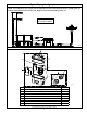
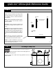
STEP 4 Rough-in (built-in installation)
1) Attach fl ange extension with closet seal onto toilet bowl
as shown at right.
2) Slide bowl up to wall and mark wall in order to connect
to opposite side. Mark location for closet bolts. Remove
bowl and set aside. Install closet bolts at locations
previously marked.
3) Attach other fl ange extension with closet seal onto pump
unit on opposite side of wall.
4) Cut 3" schedule 40 PVC pipe to the appropriate length
in order to connect pump unit to toilet. Maximum
recommended length is 18 inches. Once all piping is
dry-fi t per step 5, clean, prime, and solvent weld the 3"
PVC pipe into the fl ange extension.
STEP 4-4
STEP 4-3
STEP 4-2
STEP 4-1
SK2616
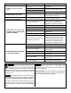
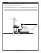
STEP 5 Piping
1) Cut and dry-fi t the pipe and fi ttings as required for
1" diameter discharge pipe (may be reduced to 3/4"
diameter if codes permit).
2) While dry-fi tting the discharge pipe, position and mark
the location of the pump unit discharge fi tting.
3) Cut and dry-fi t 1-1/2" vent pipe as required to ensure
that the vent pipe does not interfere with other
components. Make the connection to the pump
unit with the provided street elbow. A 2" x 1" 90°
discharge fi tting and a 1½" street elbow have been
provided, however, it may be easier to pipe straight
up depending on the installation.
Proper venting is required for the toilet to
fl ush. Do not use a mechanical type vent.
4) Temporarily set the toilet in place to check that there
is no piping interference. Remove the toilet and set
it aside.
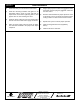
5) Clean, prime and solvent weld the discharge piping
and pump unit discharge fi tting.
When applying solvent weld to discharge
fi tting, ensure that none gets into the check valve assembly
(see Figure 5.3). Pay close attention to the proper alignment
of the discharge fi tting previously marked above.
6) Clean and solvent weld vent piping as required for
proper venting.
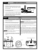
Note: Adding other bathroom fi xtures - The Qwik Jon
®
Ultima is designed to accept additional bathroom fi xtures
utilizing the two side inlets. These inlets can be attached
via the 2" MPT (outside diameter) or the 1½" slip (inside
diameter). These inlets must have the inner portion drilled
out using a 1¾" hole saw(see Figure 5.2). This is to ensure
there is no leakage problems from inlets not in use. When
utilizing side inlets, install a check valve on the incoming
line.
SK2614
SK2591
DRILL POINT
1-1/2" SLIP INSIDE
2" MPT OUTSIDE
SK2586
Figure 5.1
Figure 5.2
Figure 5.3
Discharge
Vent
Do not put glue in this area.