
Overview of Primary Product


5
© Copyright 2017 Zoeller
®
Co. All rights reserved.
QWIK JON
®
ULTIMA QWIK REFERENCE GUIDE
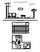
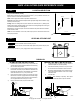
STEP 1 LOCATION SELECTION
GFCI
OUTLET
WATER
SUPPLY
DISCHARGE
PIPE
VENT
PIPE
LEVEL FLOOR
BALL OR GATE VALVE
SOLD SEPARATELY.
SK2588
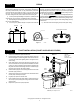
STEP 2 LEVELING OF PUMP UNIT
SK2614
SK2615
STEP 3-1
STEP 3-3, 3-4
STEP 3-2
1/8" (3 mm)
Plan your new installation carefully.
Floor: The oor should be structurally sound and level within
1
/
8
" (3 mm). If the oor is not level, use
hydraulic cement or similar material to level the oor.
Water: A water supply will be needed to operate the shower and lav.
Electrical: A GFCI (RCD) protected receptacle of the appropriate voltage will be needed to supply
electrical power to the pump.
Sewage: Access to a sewage line is required. The Qwik Jon
®
Ultima requires a 1" (DN25) [or 3/4"
(DN20) if codes permit] sewage discharge line to connect to an existing sewage line. A ball or gate
valve should be installed in the discharge line.
Vent: Access to a vent pipe is required. The use of a mechanical vent system is NOT recommended.,
as the toilet will not ush.
NOTE: If a built-in installation is to be used, locate the pump unit in an area that will allow access
to the pump and switch.
CAUTION
Do not use wooden shims to level the pump unit!
CAUTION
Ensure that nails, screws or other sharp objects do not puncture the pump unit!
Level the pump unit within
1
/
8
" (3 mm) using hydraulic cement or similar material.
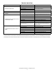
STEP 3 ROUGH-IN
1) Position the pump unit a minimum of 1/8" (3 mm) from the wall
with the inlet facing forward. Attach the bellows to the inlet using
the worm drive clamp provided.
2) Place the toilet in front of pump unit aligning the discharge of the
toilet with the inlet of the pump unit. Make sure the bellows will
bridge the gap adequately for nal installation. The toilet tank
should be a minimum of 1/2" (13 mm) from the wall.
3) Lightly mark the locations of the pump unit, toilet and closet
bolt locations on the oor. Lightly mark the wall with the height
of the pump unit and the bottom and sides of the toilet tank to
ensure against interference from pipe runs later.
4) Remove the toilet from the pump unit and set it aside.
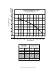
(STAND-ALONE INSTALLATION) (BEHIND THE WALL INSTALLATION)
1) Installing the grinder unit behind a wall will require an
extension kit (P/N 10-2123) sold separately.
2) Place the toilet assembly a minimum of 1/2" (13 mm) from
the wall and mark the closet bolt locations on the oor.
3) Measure the appropriate length of 3½" Schedule 40 PVC
pipe provided with the extension kit and cut it to length.
See sketch below.
4) Set toilet aside.
CAUTION
Toilet assembly is top-heavy. Take special
precautions to ensure that toilet does not tip over and break.
STEP 4-4
STEP 4-3
STEP 4-2
STEP 4-1
SK2616