
Install Instructions


8
© Copyright 2010 Zoeller Co. All rights reserved.
1) Install the closet bolts at the points marked earlier.
2) Place the toilet assembly over the closet bolts. Install
the anchoring hardware and tighten in an alternating
pattern. Check for level and shim as required. Be
careful when tightening bolts or nuts against china
to avoid cracking the china.
3) Install rubber bellows onto the toilet discharge and
grinder tank hub and secure with the worm clamps
provided for stand alone installation. See sketch
in Step 4. For built-in installation, install the rubber
couplings to both the grinder tank and the toilet
discharge and secure to extension pipe with worm
clamps provided. See sketch in Step 5.
4) Install the water supply line from the existing water
shut-off valve to the toilet water supply connection.
5) Open the water supply valve and check for leaks.
The toilet tank should fi ll to the proper level. Adjust
if required.
6) Plug the pump's power cord into the piggyback switch
receptacle and then plug the piggyback switch into
the GFCI outlet.
7) Flush the toilet and watch for proper operation. Listen
for the pump to start. The pump unit requires proper
venting in order for toilet to fl ush. Check for leaks.
8) Repeat fl ush cycles to assure proper operation.
9) Install an elongated toilet seat (supplied by
others).
10) Install the lid on the toilet tank.
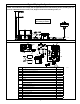
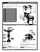
FLOOR LEVEL TO WITHIN 1/8"
PUMP UNIT
AUX. INLET
WATER
SUPPLY
GFCI
OUTLET
DISCHARGE
PIPE
VENT PIPE
(PER ALL CODES.
DO NOT USE
MECHANICAL VENT.)
SK2595
STEP 7 Toilet Installation
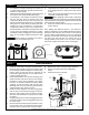
STEP 6 Piping
1) Cut and dry-fi t the pipe and fi ttings as required for
1" diameter discharge pipe (may be reduced to 3/4"
diameter if codes permit).
2) While dry-fi tting the discharge pipe, position and mark
the location of the pump unit discharge fi tting.
3) Cut and dry-fi t 1-1/2" vent pipe as required to ensure
that the vent pipe does not interfere with other
components. Make the connection to the pump unit
with the provided street elbow. A 2" x 1" 90° discharge
fi tting and a 1½" street elbow vent fi tting have been
provided for space constraints in a stand alone
confi guration. However, these are not required for a
built in installation. It will reduce Total Dynamic Head
on the system and simplify assembly on a built in
installation to utilize straight pipe. For the discharge
pipe, use a 2" straight coupling and reduce it down
to 1".
Proper venting is required for the toilet to
fl ush. Do not use a mechanical type vent.
4) Temporarily set the toilet in place to check that there
is no piping interference. Remove the toilet and set
it aside.
5) Clean, prime and solvent weld the discharge piping
and pump unit discharge fi tting.
When applying solvent weld to discharge
fi tting, ensure that none gets into the check valve assembly.
Pay close attention to the proper alignment of the discharge
fi tting previously marked above.
6) Clean and solvent weld vent piping as required for
proper venting.
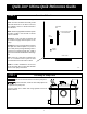
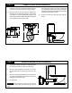
Note: Adding other bathroom fi xtures - The Qwik Jon
®
Ultima is designed to accept additional bathroom fi xtures
utilizing the two side inlets. These inlets can be attached
via the 2" MPT (outside diameter) or the 1½" slip (inside
diameter). These inlets must have the inner portion drilled
out using a 1¾" hole saw. This is to ensure there is no
leakage problems from inlets not in use. When utilizing
side inlets, install a check valve on the incoming line.
SK2591
DRILL POINT
1-1/2" SLIP INSIDE
2" MPT OUTSIDE
SK2586
SK2589