User Manual H.264 Standalone DVR ZMD-DT-SFN6 For further help, please visit www.zmodo.
Contents Chapter One Product Description...............................................................................................................3 1.1 General.........................................................................................................................................3 1.2 Technical Parameters....................................................................................................................3 1.3 Open Case And Connect Cable....................................
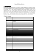
Chapter One Product Description 1.1 General Description This equipment is designed specifically for the field of a number of digital security surveillance products, which uses an Embedded Processor Init (MPU) and operating systems, combined with the field of the latest IT technologies, such as video and audio encode/decode, high-capacity hard disk recorder, TCP / IP network technology, code in FLASH, making system operation more stable.
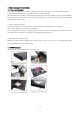
1.3 Open Case and Connect Cables 1.3.1 open-case inspection First of all, plz check if there is apperant damage of the packing as soon as you received the products. The material can protect from the damage very well in the transportation. Secondly, take out the product, and take away the protection film from the DVR to check if there is damage. Thirdly, open case, check if there is any loose of data cable of front panel, power cable, connection between fan power and mother board 1.
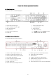
Chapter Two: Structure Appearance Description 2.1 Panel Description 16 channel DVR Front Panel Description: 7.MULTI: Multi-picture Key 1.PW: Power Indicator Light 2.HDD: Hard Disk Indicator Light 8.0-9 Number Key 3.REC: Recording Key 9.ESC: ESC Key 4.FN: Reserved 10.MENU: Menu Key 5.PLAY: Video Playback Key 11. 6.Power Key 12.USB: Standard USB Interface Direction Key Enter Key 2.
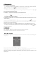
2.3 Remote Control Description POWER Power switch Device button: after press "DEV", input the same number as device DEV number and press “ENTER” to save the setting.
3.3.2 Menu composition Menu component units as following: (1) Check box: two kinds of status available, "√" means valid, "□" means invalid , direction key:【↑】 【↓】【←】【--->】,enter key【 】. Also, click the left mouse button to choose. For example: "channel" and "video mode" check box in the video research. (2) Selection box: Select the target content according to the drop-down box options. Use 【↑】, 【↓】 key or click the left mouse button to select.
3.5 Video Playback Click "setup" menu and turn into "video playback" interface. 3.5.1 Video Search Channel: Choose the target channel by clicking the check box. means selected, means means selected, means non-selected Record mode: Choose the recode mode by clicking the check box. non-selected. Search time:Input the Starting and finishing time into edit box Search:After setup the above search condition, click "search" to begin the corresponding video file searching and show the files.
3.6 Manual record In the shortcut menu, click manual record or click 【REC】 to enter the setup the manual record interface. Manual record menu illustration Manual record menu include several parts: Channel: “☑”means open; “□”means close. All on: start all channels. All off: close all channels. OK: confirm and exit Cancel: click cancel can exit the manual record interface and back to main menu.
3.8.2 Video back up Choose the channel, and record mode; setup the search time, then begin search the file. After choosing the needed file from list box, click backup and ok, wait for process bar until 100% and show backup success. Note:USB driver pen must be FAT32 format when backup the file. 3.8.3 System setup In the setup menu, Choose “system setup” and turn into its sub menu. It includes: General setup, Encode setup, Record setup, Network setup, Screen setup, Video detection, PTZ setup, Sensor setup.
3.8.3.1 General setup Choose the "General setup" and turn into its setup interface. Time: DVR preview time. Click “refreshes” after setting, it will pop out “the recording will stop once you modify the time", and save the setting. Date Format:: Y/M/D”, “D/M/Y”, “M/D/Y”. Auto Logout: : DVR will log off if there is no operation within 10 minutes, it needs login again. Key Buzzer: Enable: there is sound with the controller or pressing key on front panel; Disable: without sound.
"AV combined" means encoding for both video and audio. Bitrate mode: choose the right bitrate mode you need: "constant bitrate” means system encoding video as user-defined bitrate and frame rate. "Variable bitrate" means system encoding according to user-defined image quality and video frame rate, but bit rate is automatically adjusted by the system depending on the video screen. "Average birtrate" means system automatically adjusted fluctuation as user- defined bitrate.
3.8.3.4 Network setup Select “network setup” from “system setup” menu. MAC address: device's MAC address. DHCP: select DHCP to get IP automatically. “☑”means works ;“□” means non-work IP address: the IP address must be unique and cannot be in conflict with the host or work station which on the same network segment. Subnet Mask: use for distinguish the network segment. Gateway: need to set the gateway address to achieve communication between the different network segments.
3.8.3.5 Screen setup Select “screen setup” from “system setup” menu Channel: chose the target channel by clicking select box. Camera title: user can edit the channel title from the edit box. “☑” means display channel title, “□”means non-display. OSD Alpha: user can adjusted the OSD menu transparency as needed. OSD time: “☑”display system time,“□” non- display; Auto Switch: user can setup the time of auto switching for preview image, it switches in single screen or 4 Channels screen.
Alarm duration: the alarm duration for after chose the trigger video detection. Area edit: setup the motion detection area by dragging left of mouse. Alarm: “☑”means start, “□”means stop. Buzzer: “☑”means start, “□”means stop. E-Mail notice: “☑” means E-Mail valid, “□” means E-Mail invalid. Copy to: select the channel and click "copy to" & ''ok " to copy the same setting to other channel. Or user can choose copy to "all" to make all channel in same stetting .
3.8.3 8 Sensor setup In "system setup" menu, choose "PTZ setup" to enter its setting interface. Channel: chose the target channel by clicking select box. Work mode: select disable or able to stop the alarm or start the alarm. Alarm duration: set up alarm duration time. Recording channel: select the target channel to make recording after alarm is triggered. Alarm: “☑” enable alarm, “□” close alarm. Buzzer: “☑”start buzzer, “□” close buzzer.
3.8.4.1 User Management Click" user management ". Add user: input a new user name in the edit box and set up the operational authority. Choose in the right check box, “☑” means the users can use it, “□” users can not use it. Click the "set password” to set the new password, or it can be the default password.
3.8.4.3 System maintenance In “management tool", click "system maintenance", enter setting interface. Auto reboot: setting automatic reboot time, it can set" Saturday to Sunday”. "Never" means do not reboot automatically. Firmware upgrade: copy firmware to the root USB disk, insert USB, select the USB storage device, and then click "start" to upgrade. When upgrade is completed, clicks “OK” then system automatically reboot. Note: 1. Firmware name should be: FWHI1504A_***. Rom (4ch), FWHI1508A_***.
In main menu, click "system info" to enter setting interface. It includes HDD info, system info and log info 3.9.1 HDD information The listbox shows current HDD status info 3.9.2 System version Device name, device model, H/W version, S/W version could be checked here 3.9.3 System log Choose log type which need to check from listbox, and input log time in the editbox, then click "search", log detail will showed below, you can turn the page by click " previous" and "next", or input target page to turn.
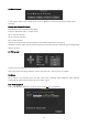
3.10 system logout In main menu, click "system logout", popup setting interface. User logout: Logout current user. After logout, if you want to use the device again, need to login. System reboot: It will reboot when click "OK". Chapter Four Esee User Manual 1. Connect DVR with network, make sure network working fine 2. Enter router to enable UPNP.As below picture, It is TP-LINK router. But for different router, UPNP might in different place, pls find and enable it. 3.
IP address: Default 192.168.1.114(User input correct IP according IP actual situation, if in 1 network segment, input 192.168.1.114,if in 0 network segment, input 192.168.0.114 ).If no IP conflict, do not need to change 114 to other IP Subnet mask: In order to distinguish subnet segment, default 255.255.255.0 Default gateway: Default 192.168.1.1(Change according to actual situation) In router running status can see gateway DNS address: Default 192.168.1.1, change your network segment DNS.
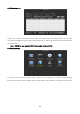
1.1 Remote Video Viewer After connecting, remote video viewer includes: preview window, PTZ control, preview mode, stream option, channel on/off, setting, configuration, playback, user logout, as below: 1-1 Open preview: In preview window, click left mouse, choose target channel, (If channel frame is red, means select).
on; off Preview mode: In preview mode switch table, can click to choose mode, or double click channel to single channel preview mode, or switch to multi-channel mode.
Lifetime Customer Support Informative Knowledge Base at kb.zmodo.com 24/7 Live Support on www.zmodo.