Installation Guide AL30 & AL40 Series Smart Lock Version: 2.
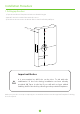
Important Notes v Please go through this Installation Guide carefully or call Customer Care before returning the product to the store. v The contents of this installation guide may vary without any prior notices to improve the performance of our product. v We highly recommend professional installation, in order to avoid any additional service charges that may be caused due to the improper installation of the product.
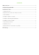
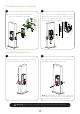
Contents What’s in the box.........................................................................................................................1 Installation Diagram(AL30B)......................................................................................................1 Installation Procedure.................................................................................................................2 1. Setting up the door.........................................................................
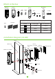
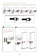
What’s in the box Outdoor assembly Indoor assembly Mounting plate Gasket Latch Strike plate Strike box Keys Screw B Screw A Stud 3M tapes Note: Please use the appropriate set of C screws as per your door's thickness, to assure the proper functioning of the locks. Screw C Screw length For door thickness 16.
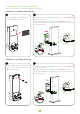
Installation Procedure 1. Setting up the door 1) Tape the Installation Template at the desired handle height. 2) Mark for the holes and drill the marked location. 3) The hole A doesn’t need to be drilled if the lock will be fixed by 3M Tapes. 35mm - 53m m A 60mm /70mm Important Notice It is not required to drill hole on the door. To aid with the stabilization of the lock during installation we have already provided 3M Tapes in the kit.
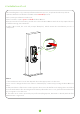
2. Adjust the backset of the lock to 70mm (if needed) Backset is the distance from the edge of the door to the center of the hole drilled on the door. The default Backset is 60mm, but if you want to change the Backset to 70mm, grasp body and twist the Faceplate as shown below: Press the Bolt inside the Latch Rotate the Faceplate Pull-out the Faceplate Rotate it back 70mm backset 60mm backset By default, the metal shaft twists over the center as shown: 3.
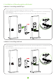
4. Installation of Outdoor assembly There are two methods to install the Outdoor assembly. v Method 1: Installing with 3M Tapes 1 Paste a 3M Tape on the Mounting plate of Outdoor assembly. 2 1) Make sure the highlighted Spindle is in the horizontal position, as shown. 2) Route the cable through the opening below the bolt. 3) Attach the Outdoor assembly to the door by inserting it through the Latch.
5. Installation of Mounting plate with Gasket v Method 1: Installing with 3M Tapes 1) Paste a 3M Tape on the Mounting plate of Indoor assembly. 2) Attach the Mounting plate to the Gasket and route the cable through the hole on the Mounting plate and Gasket. 3) Place the Gasket and Mounting plate on to the door and use 2 C screws to secure them. v Method 2: Installing with Stud 1) Attach the Mounting plate to the Gasket and route the cable through the hole on the Mounting plate and Gasket.
6. Installation of Indoor assembly 2 1 Connect the male cable to the female connector on the Indoor assembly. Place the Indoor assembly properly on the Mounting plate. Then use A screws to secure Indoor assembly. The Knob dot must be positioned in direction of Bolt. 7. Verify Mechanical Unlock 2 1 Rotate the Knob to check that Latch Bolt can be extended correctly or not. Insert the Key and rotate to check that Latch Bolt can be extended correctly or not.
8. Initialization of Lock After installing the Lock, you must perform Initialization process, as explained in the steps below: 1) Rotate the Knob to make the Latch Bolt in the extended position. 2) First, insert just 3 batteries in the Lock. 3) Use a needle or a pin to press and hold the Reset Button. 4) Now, insert the last one battery, and do not release the Reset Button until the Lock prompts “Restore to default settings, wait a moment.
9. Mark and drill holes for the Strike box and Plate 2 1 Make sure that the Strike box is in the level of Latch Bolt, then use Installation Template to drill holes. Align the Strike box and Plate with the drilled hole and use B screws to secure them. 14MM (70/127 “) 58(MM) (2-36/127 “) 21.
Warning: Any Changes or modifications not expressly approved by the party responsible for compliance could void the user's authority to operate the equipment. Note: This equipment has been tested and found to comply with the limits for a Class B digital device, pursuant to part 15 of the FCC Rules. These limits are designed to provide reasonable protection against harmful interference in a residential installation.