
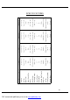
Specifications


6
ASSEMBLY AND DISASSEBLY
Figure 1.
Figure2.
Figure 3.
Figure 4.
Figure 5.
The following are the steps required to assemble
your Zip’r. Disassembly can be achieved by
following all of the steps in the reverse order.
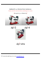
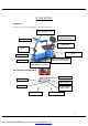
Figure 1. There are five main sections that need to
be assembled: Front frame, rear frame, battery box,
seat post, and folding seat.
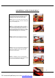
Figure 2. To begin assembly, tilt the rear frame
back so it is freely standing on the rear bumper. Lift
the front frame up and set it down onto the rear
frame by connecting (setting down) the front frame
curved locking brackets (one on each side) onto the
rear frame bracket pegs (one on each side).
Figure 3. After the steps in Figure 2 have been
completed, the scooter should be in this position.
Figure 4. Take note of the latch in the middle of the
rear frame. This latch must be pressed together
during disassembly in order to release the rear
frame from the front frame.
Figure 5. Holding the seat post, slowly pivot the
rear frame forward and down until the latch in Figure
4. locks onto the front frame locking peg.
PDF created with pdfFactory trial version www.pdffactory.com