PRODUCTS MANUAL R1V2 SERIES High Density Redundant Power Supply For 1U Chassis Rev.
INDEX 1.1 1.2 1.3 1.4 1.5 1.6 1.7 1.8 1.9 1.10 1.
1.1 INTRODUCTION First of all, thank you for purchasing R1V2 Series – High-Density Micro Redundant power supply for 1U chassis. The R1V2 is a 1+1, Hot-swappable/Hot-pluggable, High-Density Micro Redundant power supply set, it consists of: (1) complete metal frame (nickel-plated) (2) compact size 1+1 power modules (3) backplane board The R1V2 Series of hot swappable high-density micro redundant power supply offer a maximum 275 watts of output power.
1.2 PACKING Your R1V2 box package should consist of the following: (A) R1V2 *1 (B) Accessory pack (included 1 holding bracket for shipment)*1 (C) Products’ manual *1 1.3 MODEL DESIGNATION Model number identification: R1V2 – 5ZZZV4H R1V2 5 ZZZ V 4H --- Model name (AC Input) --- For 5 DC outputs (5V/12V/-12V/3.3V/5VSB) for ATX12V / EPS12V Spec. --- Total output power, ZZZ -> 275 etc. (unit: watt) --- High efficiency. --- Suit for 1U chassis (1U = 44.
1.4 FEATURES R1V2 Series --- High-Density Redundant power supply with Active Power Factor correction 1+1, Hot swappable, Hot pluggable, AC Input for 1U chassis Easy fit into 1U , 275W+275W , ATX12V / EPS12V outputs Dimension :R1V2 - 295mm(D)×106mm(W)×41.
.
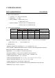
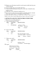
1.7 SPECIFICATIONS INPUT CHARACTERISTICS: R1V2-5275V4H A、INPUT CHARACTERISTICS: 1、VOLTAGE: 90∼264VAC FULL RANGE 2、FREQUENCY: 47∼63HZ 3、INPUT CURRENT:4A (RMS) FOR 115 VAC 2A (RMS) FOR 230 VAC 4、INRUSH CURRENT:35A MAX. FOR 115 VAC PER MODULE 70A MAX. FOR 230 VAC PER MODULE B、OUTPUT CHARACTERISTICS: OUTPUT VOLTAGE OUTPUT CURRENT MIN. MAX. +5V +12V -12V +3.3V +5Vsb 0 0.1 0 0 0.1 20 22 0.3 20 2.5 REGULATION LOAD LINE ±5% ±5% ±10% ±5% ±5% REMARK: +5V AND +3.
1.8 INSTALLATION & TESTING Turn off (Remote off) the on/off switch. Mount the power supply in the system chassis using the proper mounting tool, the mounting holes in the power supply should match those in the case. Attach the connectors to the M/B by following the M/B instructions, there are various connectors / pin-outs on both power supply and M/B. They should match each other; otherwise the connection will cause undetectable harms.
If everything works out fine, then turn off (remote off) the power system. Now put back the cover of the case and tighten with the screws that you have retained earlier. Now you have completed the installation of the R1V2 redundant power supply system. 1.9 HOT-SWAP PROCEDURES Please refer to the following when either power module or the fan found defective. A) Locate the defective power module by examining the individual LED (if LED without light, it indicates the power module is defective).
D) Replace a new Good power module, insert the power module into the power system to the end. E) Check the LED of the power module light Green. F) Check the LED indicating the total power system status. It should be from twinkle to Green. G) Tighten the screws of the power module to fix it. H) If you want to test this new power module in simulating defective situation. Please refer to the Section 1.8 Installation & Testing Section.
1.11 TROUBLE SHOOTING If you have followed these directions correctly, there should be no problem occurred. Some common symptoms are: the system doesn’t work, buzzer sounds, work for a very short period, etc., please try the following steps to verify and correct it: 1. Check all the connections (correct pinouts, loose connections, wrong direction, etc). 2. Check for short-circuits or defective peripherals by unhooking each peripheral once at a time.
The “RELIABILITY “ solution to E-application 新巨企業股份有限公司 ZIPPY TECHNOLOGY CORP. POWER DIVISION HEADQUARTERS 10F, NO. 50, MIN CHYUAN RD., SHIN-TIEN CITY, TAIPEI HSIEN, TAIWAN, R.O.C. TEL: 886-2-29188512 FAX: 886-2-29134969 WEB SITE: http://www.zippy.com.tw EMAIL: power@zippy.com.tw USA OFFICE 961 CALLE NEGOCIO, SAN CLEMENTE CA 92673, USA TEL: 1-949 366 9525 FAX: 1- 949 366 9526 EMAIL: powerusa@zippy.com Note: *The description stated herein is subject to change without prior notice.