
Owner's manual

Special Procedures For Certain Year Installations
2000 and Early Model 2001 Motorcycles – Page 7
1995-1996 Model Motorcycles – Page 8
2000 and Early Model 2001 Motorcycles
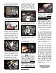
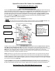
For the year 2000 and some early 2001 FL models, the Vehicle Speed Sensor (VSS) signal output wire from the
speedo terminates at the 8-pin main harness connector (see illustration below), #8A, pin 5. There is no connection
from there to the ECM and therefore no VSS signal to the ECM. This lack of data renders the ThunderMax’s
Automatic Idle Air Control Correction features inoperable and must be corrected. For late-year 2001 FL models,
this same VSS signal output is continued to the ECM from connector #8- pin 5 to ECM pin 8 (White/Green color
wire, no modification required). Simply view the Main Harness Connector to verify if the wire is needed.
The VSS wire is added to the harness as follows;
1. Remove the ECM relay and unbolt the ECM bracket from the bike.
2. Disconnect the main harness from the ECM and pull the rubber boot back to expose the ECM connector. Clip
any wire ties and remove the screw that secures the plastic terminal cover and remove the cover.
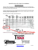
3. Slide a common plastic wire tie through the plastic main harness cover toward the ECM connector. (See Fig.
A-32, Main harness to ECM harness [8]) Using a piece of tape, attach 2” of the new wire to the wire tie and
carefully pull it through the plastic wire cover. From there it can easily be routed with the existing wires to connector
#8B, pin 5. Use a magnifying glass if necessary to identify terminal location (numbers are on connector).
Terminals 72326-95 (ECM) and 72191-94 (Main Harness Connector) are included; identify the correct terminals
and use the correct tool to crimp the terminals on the wire.
NOTE: Alternately, the new wire may be routed outside of the plastic harness cover and wire tied to the harness.
4. Separate connector #8 and remove the plastic retainer and rubber seal from side B where the terminal will be
installed (carefully pry out with a small screwdriver). Use care to insert the new wire terminal into the pin 5 opening
so that it’s positioned correctly. Replace the plastic retainer then re-install the seal last so as not to twist or damage
it. Re-connect connector ends 8A to 8B.
5. Insert the ECM end of the new wire into the ECM connector pin 8 and replace the cover. Use wire ties as
needed. Use care when inserting the new terminal so that it’s positioned the same as the existing terminals. Note
the tabs on the terminal which lock into the connector. Make sure they are tapering outward and not flattened.
See Next Page For 1995-1996 Model Instructions
Page 7
Main Harness
Connector #8
Main Harness
View from 2000 FLT
shop manual.
2001 year view is
similar with connector
#8 near the center of
the ECM and a relay
bank present.
ECM
Connector