
Owner's manual

9. Remove the remaining ring
from the rubber hose. Repeat
this process on the 2
nd
hose.
10. Attach the fuel supply and
return hoses to the manifold
using the supplied EFI clamps.
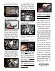
11. Place the manifold in
location under the stabilizing
link; align with supplied 3/8-16
hex bolt. Route EFI hose from
fuel rail to fitting (arrow) on
manifold block (trim for best fit;
allow gentle loop without
permitting hose to kink or touch
cylinder fins). Attach with
provided EFI hose clamps.
12. Re-install top engine mount
with link using provided 3/8-16
hex bolt and existing nut and
washers on left side (tighten to
40 ft/lbs); use supplied
buttonhead bolt and 12pt nut for
the right side link (nut on top).
13. Install throttle cables and
throttle body assembly. Attach
harnesses for TPS, MAT sensor
and IAC motor. Adjust throttle
cables for proper closed free-
play and idle to wide-open
operation.
14. Verify clearance between
buttonhead stabilizing link bolt
and IAC motor plug.
15. Install air cleaner (follow
instructions included with air
cleaner kit).
16. Install fuel tank. Re-attach
fuel hoses to tank.
17. For steps 17 & 18 the
battery positive cable should
still be disconnected. There
are several relays in the wiring
system. Locate and remove the
“ECM Power Relay” usually
under seat. This will be replaced
with supplied relay AFTER the
battery cable is reconnected.
This specially modified relay is
configured with a “stay alive”
circuit, required for your new
ECM. 2000-2001 models, see
special instructions on page 7
before proceeding.
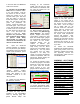
18. Remove factory ECM and
replace with supplied
ThunderMax ECM (1995-1996
model years, perform ground
wire addition explained on page
8 before installing ECM). Route
communication cable plug to
allow for easy access. After the
ECM is plugged in, connect the
battery positive cable, then
install the new ECM Power
Relay. If the lights come on or
the fuel pump runs upon relay
connection, the wrong relay was
replaced in step 17 (correct this).
Installing With AutoTune
19. If the exhaust system you
are using is not equipped with
oxygen sensor bungs, bungs will
need to be added to the exhaust
pipes. Bungs must be located
within 3”-6” from the cylinder
head. Install supplied wide band
oxygen sensors in the front and
rear exhaust pipes. Route and
tie down the sensor harnesses
away from the engine.
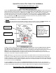
20. To mount the closed loop
module, pick a suitable location
that will allow the power/data
plug to easily reach the bike’s
diagnostic port plug, and allow
the oxygen sensor harnesses to
reach the sensor plugs. Secure
with wire ties or 2-sided foam
tape (orientation of the module is
not important). Connect the
sensors to the closed loop
module. The sensor wiring
harness for the rear cylinder
sensor is shorter and can be
easily identified by black
tracers on all of its wires. It is
very important to install this
correctly or the engine will
perform poorly!
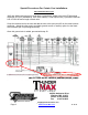
Special Procedure
for AutoTune Wiring
on Marelli Bikes: