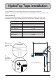
HydroTap Taps Installation For new installations, It is recommended to fit the tap prior to installing the undersink unit. Note: This book must be read in conjunction with the undersink installation manual and the user manual Hole positioning: Position the tap such that it dispenses into the sink bowl with ample clearance for a cup or tea pot. Alternatively, the tap could be mounted away from the sink using a font, available as an accessory.
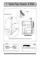
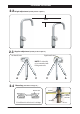
1 - HydroTap Classic & Elite EliteTap Min 300mm HydroTap Classic ALL THREAD ROD BLACK PLASTIC SPACER 335mm STAINLESS STEEL SPACER SPIDER CLAMP 470mm NUT Tap assembly exploded view and kitchen layout side view. 1.1 BENCH TOP Ø35mm 1.2 Apply a light smearing of silicon sealant on the underside of the spacer to ensure a watertight fit. Cut a 35mm hole in the bench / sink top. Page 2 of 20 803341 - Tap Installation Instructions - 02.17 - v2.
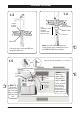
Installation Instructions 1.4 1.3 BLACK PLASTIC SPACER Fit the STAINLESS STEEL WASHER, SPIDER CLAMP, AND 6mm NUT. STAINLESS STEEL WASHER SPIDER CLAMP 6mm NUT 35mm hole Pass all the hoses, tubes and USB lead through the 35mm hole. 1.5 Note feed each of the three tubes and Note: electrical cable evenly in between the legs of the SPIDER CLAMP when installing.
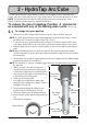
2 - HydroTap Arc/Cube The HydroTap Arc/Cube has a spout that may be fixed in one of 6 angular positions (depending on the position of the rotary control) and fixed in one of two height positions. The spout is fixed and does not swivel. NOTE: The tube kit must be fitted after the HydroTap has been mounted on the benchtop or sink. Refer to the tube kit assembly instructions, supplied with the tap kit. To reduce the risk of scalding, Position A should not be selected with any of the Boiling water units.
Installation Instructions 2.2 Height adjustment (Fixed position options) 50mm 2.3 Angular adjustment (Fixed position options) Left Hand Control Right Hand Control NOTE: Position A is not recommended with Boiling water units A 2.4 B C C B A Mounting (See table on Page 11 ) BENCH TOP O-RING LOWER RUBBER WASHER Ø35mm WASHER Cut a 35mm hole in the bench / sink top. 803341 - Tap Installation Instructions - 02.17 - v2.
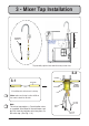
Min 300mm 3 - Mixer Tap Installation BRAIDED HOSE x 3 Tap assembly exploded view and kitchen layout side view. 3.2 O-RING 3.1 SINK TOP 35mm Cut a 35mm hole in the bench / sink top. WASHER LOWER RUBBER WASHER NUT Note: make sure the tap location will allow the nozzle to drain into the sink. Note Note: The mixer tap requires a Restrictaflow valve, as supplied, to be fitted in the cold water supply line, from the isolation valve tee piece, to the mixer tap. (See Fig. 1.
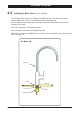
Installation Instructions 3.3 Installing the Mixer Tap (Classic, Arc and Cube) • Fit the O-ring into the recess on the underside of the Mixer tap. (Note: If mounting on an uneven surface, a light smear of silicone on the O-ring will ensure a water tight seal) • Pass the tap tubes and threaded extension through the 35mm hole and position the tap so that it discharges into the sink. • Fit the lower rubber seal to the threaded extension. • Secure the tap in position with the metal washer and Nut.
Installation Instructions Typical HydroTap 4-in-1 Installation (see section 5) 3.4 POWER CORD USB CHILLED OUTLET MAINS IN CLEAR RED WHITE BLUE Note: All silicon tubes must be cut to size. They must have a constant fall back to the unit.
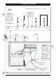
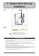
4 - Classic All-In-One Tap Installation 335mm Min 300mm 4.1 470mm 4.2 SINK TOP 50mm Cut a 50mm hole in the bench / sink top. Note: make sure the tap location will allow the Note nozzle to drain into the sink.
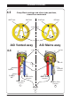
Installation Instructions 4.3 Clamp Block markings and silicon tube positions, viewed from underneath BLUE mark WHITE mark BLUE mark RED mark SILICON TUBES R B B R C C USB CABLE AIO Vented assy AIO Mains assy CLAMP BLOCK 4.
Installation Instructions Typical Vented assembly 4.5 • Screw the braided hoses into the extension tubes. Ensure the o-rings are lubricated prior to assembly and that the braided hoses, with coloured markings, are correctly matched with the colours on the extension tubes and on the clamp block (as indicated). Vented braided hose positions WHITE Mains IN CLAMP BLOCK Extension tubes • Make sure all tubes and hoses are firmly secured.
Installation Instructions Typical All-In-One Vented assembly with Booster heater 4.7 Note: All silicon tubes must be cut to size. They must have a constant fall back to the unit.
5 - Celsius All-In-One Tap Installation 5.1 Special Tools Required: In addition to normal tools, the following will be required: • 50mm diameter hole saw for timber bench tops. (Not supplied) Min 300mm • 50mm diameter sheet metal hole punch for sink tops. (Not supplied) Clearance 335mm • 54mm AF tube spanner or wrench (Not supplied) for fixing tap assembly. 464 5.2 BENCH TOP 5.3 Ø 50mm Cut a 50mm hole in the bench / sink top.
Installation Instructions 5.4 220mm (Hot & Cold Outlet) 439.5 Swi ng 255 258 ng Swi 42.9 +RW &ROG :DWHU 2XWOHW 85 151 %RLOLQJ :DWHU 2XWOHW 6WHDP 9HQW 2XWOHW &KLOOHG :DWHU 2XWOHW Underside of spout of Celisus AIO tap. 5.5 Note: Trim all plastic tubes to minimise any dead leg of water. O-RING SEAL BLACK RUBBER SEAL STEEL WASHER BRASS NUT HOT & COLD BRAIDED HOSES USB PLUG Page 14 of 20 803341 - Tap Installation Instructions - 02.17 - v2.
Installation Instructions 5.
Installation Instructions Typical All-In-One Mains Installation 5.7 Note: All silicon tubes must be cut to size. They must have a constant fall back to the unit. RED Boiling BLUE Chilled Tee piece (Supplied) Note: - Mains hose length is 750mm - Plug and Cord length is 1800mm Position the under sink unit close to the outlet tap, within reach of the hose and cord lengths supplied External HOT & COLD isolation valves (Not supplied) Page 16 of 20 803341 - Tap Installation Instructions - 02.17 - v2.
6 - Celsius Tap Installation Special Tools Required: In addition to normal tools, the following will be required: • 35mm diameter sheet metal hole punch for sink tops. (Not supplied) • 35mm diameter hole saw for timber bench tops. (Not supplied) • 42mm AF tube spanner or wrench (Not supplied) for fixing tap assembly. NOTE: Taps are available with ARC or CUBE neck options. Hole positioning: Position the tap such that it dispenses into the sink bowl.
CSHA Tap connections 6.1 BENCH TOP Ø35mm Cut a 35mm hole in the bench / sink top. Chilled Sparkling Tap components 6.2 Note: Trim all plastic tubes to minimise any dead leg of water. BLACK RUBBER Seal RUBBER Washer BRASS WASHER BRASS NUT USB PLUG HOT & COLD BRAIDED HOSES Page 18 of 20 JG Y-PIECE CHILLED TUBE SPARKLING TUBE 803341 - Tap Installation Instructions - 02.17 - v2.
BHA and CHA Tap connections 6.3 Boiling model Vent outlet BLACK RUBBER SEAL BRASS WASHER RUBBER Washer USB PLUG BRASS NUT VENT TUBE BOILING or CHILLED TUBE HOT & COLD BRAIDED HOSES 803341 - Tap Installation Instructions - 02.17 - v2.
Tap Installation 6.4 • Pass all the hoses, tubes and USB lead through the 35mm hole. • Ensure the black rubber seal is correctly positioned to give a water tight seal • Secure the rubber & brass washers and large nut from inside the cupboard space, as shown. Boiling model Vent outlet BLACK RUBBER SEAL RUBBER WASHER 35mm HOLE IN BENCH TOP FIT THE RUBBER WASHER, BRASS WASHER, AND LARGE NUT Head Office Zip Heaters (Aust) Pty. Ltd.