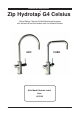
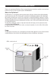
Installation Instructions ® Zip Hydrotap G4 Celsius Filtered, Boiling, Chilled and Chilled Sparkling drinking water with unfiltered Hot and Cold ambient water, for residential kitchens ARC CUBE Affix Model Number Label Here 802149 802149 - BHA; CHA; CSHA -Installation Instructions - 09.2016 - v2.
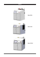
Models Model BHA Model CHA Model CSHA Page 2 of 28 802149 - BHA; CHA; CSHA -Installation Instructions - 09.2016 - V2.
Index Specifications Installation check list .................................................................................................................... 4 General Product Features ............................................................................................................ 5 Important Safety Instructions ....................................................................................................... 6 Warnings and Regulatory Information........................................
Installation checklist Before Installation: A. Read the instructions and check if there is adequate space to mount all of the components. B. Note: Not all fittings are supplied with the appliance kit. Isolation valves are not supplied. C. Check the mains water pressure is between 172-700kPa for BHA & CHA or 250-700kPa for CSHA units D. Check the water quality to determine if extra filtration will be required. NOTE: This product must be fitted to a potable water supply E.
General Product Features Thank you for purchasing a Zip Celsius. Please read and follow these instructions carefully to ensure safe and trouble free service. If service is required, please call 1800 638 633 What is the Zip Celsius ? The Zip Celsius is a conventional flick mixer tap that dispenses, Boiling or Chilled still and Chilled Sparkling water from the same outlet. The Celsius units are under bench drinking water appliances with a dispensing tap mounted on a kitchen sink or bench.
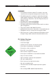
Important Safety Instructions This manual contains important safety, Installation instructions for the Zip Celsius. Safety This appliance is not intended for use by persons (including children) with reduced physical, sensory or mental capabilities, or lack of experience and knowledge, unless they have been given supervision or instruction concerning use of the appliance by a person responsible for their safety. Children should be supervised to ensure that they do not play with the appliance.
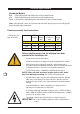
Important Safety Instructions WARNINGS 1. 2. 3. 4. 5. 6. 7. 8. 9. The Zip Celsius unit must be earthed. The resistance of the earth connection from each exposed metal part must be less than 1 ohm. All Installation and service work must be completed by trained and suitably qualified Tradespeople. Faulty operation due to unqualified persons working on this product, or any other Zip product may void warranty coverage. All Plumbing must comply with AS/NZS3500.
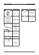
Major components and accessories Parts supplied Description Accessories Description 1 off Tap with hoses Replacement CO2 Gas Cylinder 1 off Undersink Unit with air and water filters Replacement Filter 1 off Mains water connection hose Vent Kit 1 x Inlet vent 1 x Outlet vent 9 x Screws 1 x Tee piece for ambient water supply Guide 1 x User guide and 1 x Quick start guide 1 off CO2 gas cylinder and regulator assy Page 8 of 28 802149 - BHA; CHA; CSHA -Installation Instructions - 09.2016 - V2.
Technical Specifications Residential Models: BHA = Filtered Boiling water with unfiltered Hot and Cold Ambient water CHA = Filtered Chilled water with unfiltered Hot and Cold Ambient water CSHA = Filtered Chilled and Sparkling water with unfiltered Hot and Cold Ambient water Note: chilled water will continue to be dispensed after the rated capacity has been used, although this may be at slightly higher temperature.
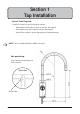
Section 1 Tap Installation Special Tools Required: In addition to normal tools, the following will be required: • 35mm diameter sheet metal hole punch for sink tops. (Not supplied) • 35mm diameter hole saw for timber bench tops. (Not supplied) • 42mm AF tube spanner or wrench (Not supplied) for fixing tap assembly. NOTE: Taps are available with ARC or CUBE neck options. Hole positioning: Position the tap such that it dispenses into the sink bowl.
CSHA Tap connections 1.1 BENCH TOP Ø35mm Cut a 35mm hole in the bench / sink top. Chilled Sparkling Tap components 1.2 Note: Trim all plastic tubes to minimise any dead leg of water. BLACK RUBBER Seal RUBBER Washer BRASS WASHER BRASS NUT USB PLUG HOT & COLD BRAIDED HOSES JG Y-PIECE CHILLED TUBE SPARKLING TUBE 802149 - BHA; CHA; CSHA -Installation Instructions - 09.2016 - v2.
BHA and CHA Tap connections 1.3 Boiling model Vent outlet BLACK RUBBER SEAL BRASS WASHER RUBBER Washer USB PLUG BRASS NUT VENT TUBE BOILING or CHILLED TUBE HOT & COLD BRAIDED HOSES Page 12 of 28 802149 - BHA; CHA; CSHA -Installation Instructions - 09.2016 - V2.
Tap Installation 1.4 • Pass all the hoses, tubes and USB lead through the 35mm hole. • Ensure the black rubber seal is correctly positioned to give a water tight seal BLACK RUBBER SEAL Boiling model Vent outlet RUBBER WASHER 35mm HOLE IN BENCH TOP FIT THE RUBBER WASHER, BRASS WASHER, AND LARGE NUT Secure the rubber & brass washers and large nut from inside the cupboard space, as shown above. 802149 - BHA; CHA; CSHA -Installation Instructions - 09.2016 - v2.
Section 2 Ventilation When installing air flow ducts, the following tools will be required: • Jigsaw and • Keyhole or Wall Board saw. 2.1 Ventilation for All Models Proper air circulation must be provided for all Boiling and Chilled models. The system will operate correctly only if the recommended air gaps are achieved during Installation. The minimum requirement is for a 50mm air gap either side and 300mm above of the undersink unit.
Ventilation 2.2 The following instructions are critical if there is insufficient cupboard air circulation. If the air flow, using the silicon door buffers, is insufficient, it will be necessary to fit a standard vent kit, which ensures heat dissipation through natural convection via installed vents. For high use applications, where the cupboard space temperature is near 35°C, or higher, the inlet vent (See Item B below) and silicon buffers, need to be fitted.
Ventilation 2.3 Typical Cut out procedure for B D Mark out and cut the air inlet and door outlet holes as shown 2. Ensure the air inlet vent and air outlet vent are positioned at opposite ends of the same cupboard space. 3. Fit the inlet vent, as shown and secure with 5 screws 4. If required, fit the outlet vent, as shown in the hottest part (top) of the cupboard and secure with 4 screws 1. Air inlet vent B Cutout deatils Page 16 of 28 802149 - BHA; CHA; CSHA -Installation Instructions - 09.2016 - V2.
Section 3 CSHA - CO2 Cylinder 3.1 Secure the cylinder mounting Secure the gas bottle supplied to a suitable wall, within 1 metre of the unit, in an upright position. This is done by screwing the metal plate holding the Hook-and-loop strap to a cupboard wall, 200mm above the floor or base of the cupboard. Make sure the gas bottle can stand before securing to the wall. Due to regulatory requirements the gas bottle must be stored securely and in an upright position. 3.
CO2 Connections CO2 pressure set zone -2.7-3.0 bar After replacing a bottle or after making a gas connection: Stage1: Turn the gas OFF 2. Using soapy water applied with a sponge, or with a brush, cover all of the gas joints with a liberal amount of soap suds. 1. Stage 2: Turn ON the gas 2. Inspect the joint for leaks 3. If any bubbles appear, the joint will need to be resealed. 1. Faulty seal joint Page 18 of 28 802149 - BHA; CHA; CSHA -Installation Instructions - 09.2016 - V2.
Section 4 Undersink Unit Installation 4.1 Hose fitting Install the mains water braided hose to the undersink unit before locating the unit in place. Note: The connection hoses supplied with the tap head assembly and cold inlet CANNOT be lengthened. Note: Insulate the Blue and White tubes after trimming to length John Guest fittings (Insertion and removal) Be careful when cutting the poly tube so that there are no rough edges and that the tube is not distorted. 1. 2. 3. 4. 5.
BHA Installation Note: Before you install a unit, determine whether a water softener or an external filter is required. 4.3 External Bypass Valve The diverter bypass valve allows the user to choose to have the boiling feed water bypass the internal filter and only be filtered by the external filtration. This diverter valve is located at the rear panel of the Zip HydroTap undersink unit, see the image below.
Installation Instructions Note: All silicon tubes must be cut to size. They must have a constant fall back to the unit. CLEAR RED Model BHA BRAIDED 4.
Installation Instructions Model CHA BLUE Note: All silicon tubes must be cut to size. They must have a constant fall back to the unit. BRAIDED 4.
Installation Instructions 4.
Section 5 Commissioning The Celsius is now ready to be commissioned. • Turn ON the water and check for any leaks. • Turn the power ON at the GPO and at the side of the undersink unit. • Familiarise yourself with the operation of the Tap, in preparation for use (See User Guide). • Select the language option from the view screen. • Follow the Installation instructions below (and review Section C of the User Guide).
Commissioning 1. 2. 3. 4. 5. Press [Start] [Stop] buttons to start and stop the filter flush. Turn the flush line stop cock ON (See diagram). Press [Start] and allow at least 10 litres of water (1 x Std Bucket) to flush through the filter. For convenience, the product details will be displayed in the screen. Once the filter flush is finished, Turn the stop cock OFF then press [Stop] to end filter flush mode.
Trouble Shooting System Fault Message Power board fault Interface fault Level board fault Condenser screen blocked Water leak, Isolate mains Compressor over-run Water supply failed Hot sensor Open Hot sensor Closed Cold sensor Open Cold sensor Closed Flood sensor Open Condenser sensor Closed Condenser sensor Open Heater fuse / driver fault Heater driver fault Compressor driver fault Hot sensor degraded Condenser overtemp.
Notes 802149 - BHA; CHA; CSHA -Installation Instructions - 09.2016 - v2.
Contact Details Head Office Zip Heaters (Aust) Pty. Ltd. ABN: 46 000 578 727 67 Allingham Street Condell Park NSW 2200 Postal: Locked Bag 80 Bankstown 1885 Australia Website: www.zipindustries.com Facsimile: (02) 9796 3858 Telephone: (02) 9796 3100 Sales & Service. Free Call: 1 800 63 86 33 Customer Care. Free Call: 1 800 42 43 44 WMK25927 AS/NZS 3718 As Zip policy is one of continuous product improvement, changes to specifications may be made without prior notice.