Quick Start Installation Guide Zenith HydroTap G5 Command Centre Boiling, Boiling / Ambient models AFFIX PRODUCT LABEL HERE Visit our website to download the manuals Quick Start Installation Guide 806836NZ v1.00 01.
Table of contents SECTION 1: Using these instructions...................................................................3 SECTION 2: IMPORTANT SAFETY INSTRUCTIONS.............................................. 4 SECTION 3: WARNINGS & REGULATORY INFORMATION................................... 6 SECTION 4: Technical data................................................................................. 8 SECTION 5: Parts supplied..................................................................................
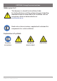
SECTION 1: Using these instructions Before you start ! This document is a Quick Start Installation Guide. For further details on installing and operating your HydroTap, download & read the Command Centre installation and user instructions, which can be found online at: zenithwater.co.nz Read and use the instructions supplied with individual kit components for a safe installation. Explanation of symbols ! !! ! Read the instructions WARNING Quick Start Installation Guide 806836NZ v1.00 01.
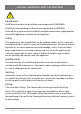
SECTION 2: IMPORTANT SAFETY INSTRUCTIONS ! Compliance In NZ/Australia electrical installation must comply with AS/NZS3000. In NZ/Australia plumbing installation must comply with AS/NZS3500. In the UK the system must be installed in accordance with water supply byelaws, current IEE regulations and local authority byelaws.
SECTION 2: IMPORTANT SAFETY INSTRUCTIONS Airflow The Zenith HydroTap operates within the ambient temperature range 5ºC - 35ºC. Proper air circulation must be provided. The system will operate satisfactorily only if the recommended air gaps are provided. The vent kit supplied must be fitted. Altitude Water boils at varying temperatures at different altitudes. The HydroTap adjusts for this during startup calibration and will recalibrate itself on a regular basis.
SECTION 3: WARNINGS & REGULATORY INFORMATION ! • For continued safety of this appliance it must be installed, operated and maintained in accordance with the manufacturer’s instructions. • This appliance may deliver water at high temperature. Refer to the Plumbing Code of Australia (PCA), local requirements and installation instructions to determine if additional delivery temperature control is required. ! • • • • • • • • The Zenith HydroTap must be earthed.
SECTION 3: WARNINGS & REGULATORY INFORMATION • Valve and fitting threads must be sealed appropriately with PTFE tape where compression seals are not provided. • Always flush new filter before use. • Do not connect Booster to electrical supply until commissioning. • Do not over tighten plumbing and hose connections. • Braided hoses supplied cannot be lengthened. • The power cord and general power outlet must be in a safe and accessible position after installation.
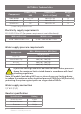
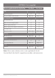
SECTION 4: Technical data Component Power rating kW Dimensions W x D x H (mm) Weight (kg) 280 x 313 x 333 280 x 313 x 335 280 x 313 x 335 13 13 13 B100, BA100 1.8 + 2.2* B60, BA60 1.8 B, BA Home 1.35 * power rating of the booster Electricity supply requirements 220-240V 50Hz AC (for power requirement see table above).
SECTION 5: Parts supplied Parts supplied with the HydroTap For Work For Home Optional Optional Command Centre Mains electrical supply cable Water supply inlet hose Water supply inlet adaptor and strainer Ventilation kit Water block kit (UK only) (UK only) Optional Optional Optional Optional Optional Tap HydroTap tap kit Separate Mains mixer Tap kit Command Centre Booster Booster & hoses Filters Water filter & instructions Limescale filter kit F
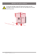
SECTION 6: Set up the ventilation 200mm ! A clearance envelope around all Command Centres must be provided to allow ventilation for the safe and effective use of the HydroTap system. Comm 50mm and Ce 10 ntre w idth Quick Start Installation Guide 806836NZ v1.00 01.
SECTION 6: Set up the ventilation B20, BA20, B Home, BA Home models • Cold air is drawn in through the inlet vent and lower gap provided by the door buffers. • Inlet vent is mounted over cupboard side, door or floor cut-out. • Warm air is exhausted through the upper gap provided by the door buffers. Air outlet 4mm door buffers (supplied) Air inlet Inlet vent All models If cupboard temperature exceeds 35°C, additional ventilation is required.
SECTION 7: Connect the water supply ! Valves and fittings must be sealed with PTFE tape if compression seals are not included. Note Mixer tap installations also use a ‘Tee piece’ as part of the water supply plumbing connections, see the Tap installation instructions supplied with the Mixer Tap to connect the water supply if using the mixer tap option. Note correct strainer orientation.
SECTION 8: Set the bypass & install the Limescale filter Available as optional accessory - UK only. For filter head installation use the guide supplied with the filter head. For Limescale filter installation use the guide supplied with the filter. ! Flush filter before use. Water out Bypass in see page 17,18 Water in Bypass out see page 17,18 Insert Remove Insert Bypass valve (Rear of the Command Centre) Remove Quick Start Installation Guide 806836NZ v1.00 01.
SECTION 9: Fit the Booster • Supplied with selected models, or available as an optional accessory. Booster c 10⁰ a b 15⁰ d f e Note Take care not to break the clips when removing or installing the Booster. 14 Quick Start Installation Guide 806836NZ v1.00 01.
SECTION 10: Connect the Booster Booster ! ! Do not connect to electrical power until commissioning. Do not over tighten hose connections. Braided hoses supplied cannot be lengthened. Cold water into Booster, connect to Command Centre BYPASS OUT see page 17,18 Strainer Hot water out of Booster, connect to Command Centre BYPASS IN see page 17,18 3/8" BSP connections Booster Quick Start Installation Guide 806836NZ v1.00 01.
SECTION 11: Connect the Command Centre Generic installation instructions For HydroTap, mixer tap and any optional accessories, use instructions supplied with individual kit components. Mains power cable USB Tap Braided hose HydroTap Do not connect to the mains socket until commissioning ! Command Centre Installation diagrams are for illustrative purposes only. Hoses are not shown to scale and cannot be lengthened.
USB CHILLED OUTLET BYPASS OUT MAINS IN MIXER OUT MIXER BOILING BYPASS VENT IN OUT IN BYPASS OUT SECTION 11: Connect the Command Centre B60, B100, B Home models USB AINS N AINS IN Booster (selected models) and limescale filter (optional) BC res RED USB VENT BYPASS OUT Limescale Filter Booster Zenith Vented ! Mixer Tap Mains connections MAINS MIXER MIXER BOILING BYPASS Water (ifOUT supplied) IN IN OUT IN CHILLED OUTLET check positi CLEAR B res comm USB MAINS IN MIXER OUT B Res Comm MI
USB CHILLED SPARKLING OUTLET OUTLET CO2 IN MAINS IN MIXER OUT MIXER BOILING BYPASS VENT IN OUT IN B Res Comm SECTION 11: Connect the Command Centre BA60, BA100, BA Home models BCS res Booster (selected models) and limescale filter (optional) Zenith Vented !MAINS Mixer MIXER Tap MIXER Mains IN OUT IN connections Water (if supplied) USB Booster BOILING BYPASS VENT OUT IN RED BYPASS OUT Limescale Filter USB CHILLED OUTLET SPARKLING OUTLET CLEAR CO2 IN BLUE BA res comm AINS N USB MAINS I
SECTION 12: Commissioning ! ! 1 See User Guide 5 7 Unpack, moisten o-rings & fit filter Boiling calibration 2 8 Filter flush Boost enable if Booster fitted Connect electricity 3 9 Monitor display screen Flush 10 Litres through 4 6 TANK FLUSH 12:12 PM Follow the prompts to flush fresh water through the tank/s 3 times as shown by the cycle counter/s. Power off Pull levers forward Power on The tank/s will fill automatically but when prompted use the tap to dispense and empty.
Refer to User Guide for operation and maintenance. Zenith Heaters Limited IRD/GST No. 95 640 729 18 Kawakawa Place, Westgate, Auckland 0814 New Zealand Ph: +(64 9) 838 8612 | Free Call 0800 558 055 zenithwater.co.nz AU02691 20 Quick Start Installation Guide 806836NZ v1.00 01.