Installation and Operating Instructions ® Zip Hydroboil Filtered instant boiling water 01552 01551 03552 03551 05552 05551 07552 07551 Zip Hydroboil 1.5 Litre White Zip Hydroboil 1.5 Litre Stainless Steel Zip Hydroboil 3 Litre White Zip Hydroboil 3 Litre Stainless Steel Zip Hydroboil 5 Litre White Zip Hydroboil 5 Litre Stainless Steel Zip Hydroboil 7.5 Litre White Zip Hydroboil 7.
Page 2 of 12 Zip Hydroboil - Installation & Operating Instructions - 85264 - June 2004
Contents Read These Warnings First . . . . . . . . . . . . . .4 Installation Requirements . . . . . . . . . . . . . . .4 Installation Procedures . . . . . . . . . . . . . . . . .5 Step 1 – Positioning . . . . . . .5 Step 2 – Fastening . . . . . . . .5 Step 3 – Connecting . . . . . . .6 a) Plumbing . . . . . . .6 b) Venting . . . . . . . . .6 c ) Electrical . . . . . . .6 Step 4 – Assembling . . . . . . .6 Step 5 – Commissioning . . .6 Wall Mounting Template Dimensions & Electrical Diagram . . . . . . . . .
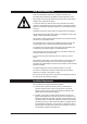
Read These Warnings First Please read all installation requirements, installation procedures and precautions before installing any Zip Hydroboil instant boiling water heater. Never attempt to install any Zip Hydroboil instant boiling water heater without reading all of the applicable instructions. In some hard water areas where mineral scale accumulation in the boiling chamber of the Zip Hydroboil may become a problem, consideration should be given to the maintenance required.
Installation Requirements continued c) Cold water supply with a minimum working pressure of 1 bar (100 kPa) and a maximum working pressure of 7 bar (700 kPa) connected via an isolation valve. d) Outlet drainage to a sink draining board or to a drip tray. e) Access to drainage from a vent situated at the base of the heater. If the water pressure is likely to exceed 7 bar (700 kPa), a 3.5 bar (350 kPa) pressure reducing valve must be installed in the cold water supply line.
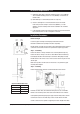
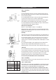
Installation Procedures Continued Step 3 – Connecting a) Plumbing 250mm Wring For exposed plumbing connection, connect the cold water inlet pipe from the base of the heater directly to the 15 mm or half-inch compression fittings with the nuts and olives provided. 45 mm For concealed plumbing connections, connect the cold water pipe through the rear of the chassis using a 15 mm or half-inch capillary elbow. Concealed Vent Concealed Inlet Cold water pipes must be flushed before connection to the inlet.
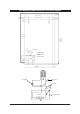
Wall Mounting Template Dimensions & Electrical Diagram 150 CLEAR 274 (1.5 L & 3.O L) 38 (1.5 L & 3.0 OL) 53 (5.0 L & 7.5 L) 38 (1.5 L & 3.O L) 304 (5.0 L & 7.5 L) 53 (5.0 L & 7.5 L) 19 65 CLEAR 318 5.O L 416 3.O L 448 5.O L 561 7.5 L 56 POSITIONING PIN COLD INLET VENT EXTERNAL PLUMBING ELECTRICAL WIRING POSITION INTERNAL PLUMBING 72 15 25 35 42 20 BENCH TOP reset t.o.l. fascia lights thermostat tº t.o.l.
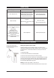
Problem Solving Sympton Possible Cause Solution Fails to dispense water. Water isolating valve turned off. Blocked filter, blocked meter tube, blocked strainer, jammed ball valve assy, airlock in transfer tube. Check water supply valve. Contact Zip authorised agent. No power. Water not boiling. Runs out of boiling water and fails to refill. Outlet tap drips. Overflow from vent. Excessive steam from vent. Power “on” but no heat. Overload repeatedly tripping with excessive steam.
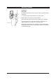
Operating Procedures Tap Operation Boiling water Zip Hydroboil is fitted with a two-way cool-touch safety tap for filtered instant boiling water. For instant boiling water, gently pull the top of the tap forward. Boiling water will flow until the tap handle is released. This operation gives fingertip flow control for safe filling of cups and mugs. To fill larger vessels such as teapots and saucepans, rotate the tap 180 degrees and depress it until it locks into a horizontal position.
Spare Parts Page 10 of 12 Key Part No Description 1 90487 Cistern Lid Clamp kit 2000B 2 90488 Cistern Lid and Gasket kit 2000B 3 90490 Gasket kit Hydroboil 2000B 4 90083 Float valve kit w/ seals 2000B 5 90069 Jumper valve kit w/ seals 2000B 6 90102 Cistern float kit w/ nut and screw 7 90493 Metering tube kit 1500w 2000B 7 90494 Metering tube kit 2400w 2000B 8 90495 Banjo screw Hydroboil 2000B Version 2 9 90496 O-Ring kit Hydroboil 2000B 10 90574 Fascia lens kit 2000B 11
3 7 12 19 8 22 9 3 20 21 17 9 18 16 11 10 24 13 3 5 4 6 1 2 9 23 26 25 14 15 Spare Parts Zip Hydroboil - Installation & Operating Instructions - 85264 - June 2004 Page 11 of 12
Warranty Information The Zip appliance you have chosen is precision-built from the finest materials available and should give many years of trouble free service. Certain warranties may be implied by law into your contract with Zip. The warranty provided below is additional to these implied warranties and nothing set out below shall limit your statutory rights or rights at law.