
Operating instructions


Page 9 of 12 Zip Hydroboil - Installation & Operating Instructions - 85264 - May 2013 v1.01
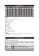
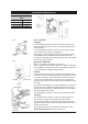
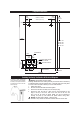
Template Dimensions
38mm
1.5-3.0L
53mm
5.0-7.5L
65mm
Clearance
56mm
POSITIONING PIN
ELECTRICAL WIRING POSITION
COLD INLET POSITION
CONCEALEDVENTPOSITION
72mm
15
25
35mm 42mm
COLD
INLET
VENT
BENCH TOP
38mm
1.5-3.OL
53mm
5.0-7.5L
19mm
20mmClearance
200mmClearance
150mm
Clearance
274mm(1.5&3.0L)
304mm(5.0&7.5L)
318mm1.5L
416mm3.0L
448mm5.0L
561mm7.5L
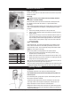
Warning:Thisappliancemustbeearthed.
Followingremedialservicetheearthingcontinuityoftheheatermustbecheckedby
aqualifiedtechnicianusinganappliancetester,orcontinuitytesterofaccuracyClass
5 or better. Class 5 denotes an accuracy of 5% full scale deflection.
1. Isolatepowersupply.
2. Setmeterto0ohmwithleadsconnectedtogether.
3. Connect one test lead to the earth pin on the three pin plug.
4. Connect the other test lead to a bare patch of metal (preferably on the
edge) of the top of the cover, then to the front cover of the unit, and
then to the tap top under the plastic paddle. This can be achieved by
inserting the probe up from behind the paddle without losing water.
Warning:Thewatermaybeboiling-showextracare.
5. Testthatineveryinstancetheelectricalresistancedoesnotexceed1ohm.
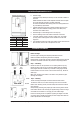
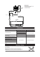
Earthing Continuity Verification & Electrical Diagram
If required, an earth continuity test
canbeperformedbytestingbetween
the earth pin on the products lead and
aexposedpieceofmetalonthecase
and the tap body.