
Operating instructions

Page 7 of 12 Zip Hydroboil - Installation & Operating Instructions - 85264 - May 2013 v1.01
Installation Procedures Continued
Step 3 – Connecting
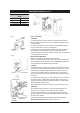
a) Plumbing
Forexposedplumbingconnection,connectthecoldwaterinletpipefromthe
baseoftheheaterdirectlytothe15mm(”)compressionfittingswiththenuts
and olives provided.
Forconcealedplumbingconnections,connectthecoldwaterpipethroughthe
rearofthechassisusinga15mm(”)capillaryelbow.
Coldwaterpipesmustbeflushedbeforeconnectiontotheinlet.Anyclogging
duetosedimentorfineswilladverselyaffecttheoperationoftheheater.
Theheatermustbeinstalledwithanisolatingvalvewhichallowsittobeisolated
fromthemainssupplyforservicing.
Water pressure requirements:
Minimum-0.07MPa(0.7bar)Maximum-0.7MPa(7bar).
Caution:Ifpressureislikelytoexceed0.7MPa(7bar),apressurelimitingvalve
mustbeinstalledinthecoldwatersupplyline.Ziprecommendsavalveratedat
3.5bar(0.35MPa)forthisapplication(ZippartNo.AQ3).
b) Venting
Aventatthebaseoftheheatermustbeplumbedtoasafevisiblelocationas,
undercertainconditions,itmaydischargecoldorboilingwaterand/orsteam.
Forexposedventplumbing,connectventoutletfromthebaseofheatertoa
15mmorhalfinchODpipewhichhasacontinuousfall,isnomorethan3
metreslong,hasnomorethan3rightanglebends,anddischargestoawaste
waterdrain.
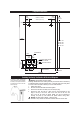
Forconcealedventplumbing(Fig.a),connectplumbingtotheventoutletfrom
theheaterrearusingacapillaryelbowprotruding45mmfromthewall.The
plumbingmustthenbedirectedtoatundishthatmustbeinavisiblelocation
beforebeingplumbedawaytowaste.
Alternativelyattachthetundishtothewall(Fig.b)andplumbawaytowaste.
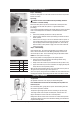
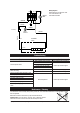
c) Electrical
Forconcealedelectricalconnection,runthepowercablethroughtherear
accessopeningoftheheatertotheterminalblockwithintheheater.
Forsurfacemountinstallationrunthepowercablethroughthecableentry
glandatthebottomoftheunittotheterminalblockwithintheheater.Ensure
thecableisfirmlysecured.
Isolationswitchesmusthaveacontactseparationofatleast3mminallpoles.
Do not turn the power ONuntilwaterflowsfromthetap.
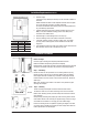
250mm
Wiring
Fig. a
Concealed
Vent
Concealed
Inlet
45mm
Fig. b
VisibleTundishVentline
Surfacemount
cable entry
TerminalBlock
Concealed
cable entry
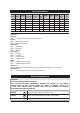
Approximate Weights When
Filled
1.5Litremodels 10kg
3.0Litremodels 12.5kg
5.0Litremodels 16.5kg
7.5Litremodels 20.5kg