
Operating instructions

Zip Hydroboil - Installation & Operating Instructions - 85264 - May 2013 v1.01 Page 6 of 12
Before You Begin
Locatethepapermounting-holetemplatepackedwiththeheater.
Readtheinstallationandoperatinginstructionscompletely.
Decidewhethertoinstallwithconcealedorexposedplumbingand/orelectrical
connections. Concealed connections are preferred for superior appearance.
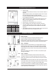
Step 1 – Positioning
Positiontheheatersothetapwilldrainontoadrainingboardordriptray.
Positionthebaseofthetaptobenotlessthan200mmabovethedraining
board(heightshouldbeincreasedonlyifessentialforfillinglargervessels).
Provideclearanceforserviceaccessofnotlessthan150mmtop,65mmleft,
20mmright.
Markcornerpositionsfortheheateronthewallsoastopositionthepaper
mounting-holetemplate.
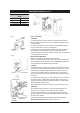
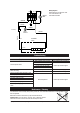
Step 2 – Fastening
Positionmounting-holetemplateonwallanddrillholeswhereshown.
Drillholesforwaterinlet,ventoutletandwiringifrearaccessisintended.
Removecoverfasteningscrews(asshownbelow)fromheaterandliftwhole
cover off heater.
Installplumbingandwiringandpreparepipeendsandwiringendsasshown.
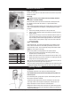
Screwheaterchassistothewallusingthesuppliedfixings,ensurethefixings
aresuitableforthesubstrate.Ifnotsupplyyourownsuitablefixings.
Ensurethemountingsurfaceiscapableofsupportingtheweightofthefilled
unit,fixingsmustbecapableofsupportingtheheaterweightwhenfilled.See
Productspecificationsforfilledweights.
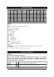
Installation Procedures
COLD
INLET
VENT
OUTLET
INLET
POSITION
VENT
POSITION
MinimumClearanceinmm
b. Electrical supply.
Astandard13ampdoublepolefusedspuronthewallwithin1500mmof
the heater.
Isolationswitchesmusthaveacontactseparationofatleast3mminallpoles.
The circuit should be protected by a suitably rated RCD.
TheelectricalinstallationshouldcomplywithcurrentIEEregulationsand
anyLocalAuthorityrequirements.
c. Apotablecoldwatersupplywithaminimumworkingpressureof0.07
MPa(0.7bar)andamaximumworkingpressureof0.7MPa(7bar)
connected via an isolation valve.
d. Outletdrainagetoasinkdrainingboardortoadriptray.
e. Accesstodrainagefromaventsituatedatthebaseoftheheater.
f. Ifthewaterpressureislikelytoexceed0.7MPa(7bar),a0.35MPa
(3.5bar)pressurereducingvalvemustbeinstalledinthecoldwater
supply line.
g. Inallinstallationinstancesthewallsoftheheatermustbeverticalandthe
basehorizontal,therecanbenoexceptionstothisrule.
Installation Requirements Continued
Size Kw Amps
1.5 Ltr 1.5kW 13 A
3.0 Ltr 2.4kW 13 A
5.0 Ltr 2.4kW 13 A
7.5 Ltr 2.4kW 13 A
Concealed
Services
Exposed
Services
Front View