Installation and Operating Instructions Zip Hydroboil ® Instant boiling water HS001 HS003 HS005 HS105 HS007 HS107 Zip Hydroboil 1.5 Litre White Zip Hydroboil 3.0 Litre White Zip Hydroboil 5.0 Litre White Zip Hydroboil 5.0 Litre Stainless Steel Zip Hydroboil 7.5 Litre White Zip Hydroboil 7.5 Litre Stainless Steel 03552 05552 05551 07552 07551 Zip Hydroboil - Installation & Operating Instructions - 85264 - May 2013 v1.
Description Wall mounted Over-sink appliance for instant boiling water. Features: • Designed to operate within 1°C of boiling point. • Temperature controls automatically cut off the power in the event of temperature control failure, boil dry cutout or a blocked vent pipe. • Incorporating a pull down tap for precision filling of cups, it also locks ‘ON’ for filling pots. • Separates the cold water supply from the boiling chamber and the internal condensing system retains steam within the heater.
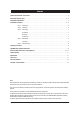
Contents Product Specifications / Accessories............................................................................................................................4 Read These Warnings First...................................................................................................................................... 4 - 5 Installation Requirements..............................................................................................................................................
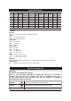
Product Specifications Delivery Recovery Capacity Cups @ any Cups per Litres one time hour Rating kW @ 230V Width mm Depth mm Height mm Weight Empty Kg Weight Filled Kg 100 1.5 289 180 335 7.0 10.0 18 100 1.5 289 180 431 8.0 12.5 5.0 30 140 2.4 318 198 465 9.5 16.5 5.0 30 140 2.4 318 198 465 9.5 16.5 White 7.5 45 180 2.4 318 198 578 11.0 20.5 s/steel 7.5 45 180 2.4 318 198 578 11.0 20.5 Model Finish HS001 White 1.5 9 HS003 White 3.
Read These Warnings First Continued Safety This appliance is not intended for use by persons (including children) with reduced physical sensory or mental capabilities, or lack of experience and knowledge unless they have been given supervision or instruction concerning use of the appliance by a person responsible for their safety. Children should be supervised to ensure that they do not play with the appliance.
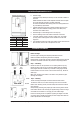
Installation Requirements Continued Minimum Clearance in mm b. c. Size 1.5 Ltr 3.0 Ltr 5.0 Ltr 7.5 Ltr Kw 1.5 kW 2.4 kW 2.4 kW 2.4 kW Amps 13 A 13 A 13 A 13 A d. e. f. g. Electrical supply. A standard 13 amp double pole fused spur on the wall within 1500mm of the heater. Isolation switches must have a contact separation of at least 3mm in all poles. The circuit should be protected by a suitably rated RCD.
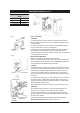
Installation Procedures Continued Approximate Weights When Filled 1.5 Litre models 10 kg 3.0 Litre models 12.5 kg 5.0 Litre models 16.5 kg 7.5 Litre models 20.5 kg Fig. a Wiring 250mm 45 mm Concealed Inlet Concealed Vent Fig.
Installation Procedures Continued Step 4 – Assembling Position the casing back on to the heater and secure with the two top and two bottom Torx screws. Tap Fitting Caution! To ensure correct fitment of the tap assembly, follow the instruction a to c below carefully. o-ring Inlet water temperature 15°C 10°C 1.5 Litre models 10 min 11 min 3.0 Litre models 16 min 17 min 5.0 Litre models 16 min 17 min 7.5 Litre models 23 min 24 min Remove the black plastic cap from the hot outlet tube.
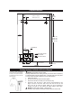
Template Dimensions 38mm 1.5-3.0L 53mm 5.0-7.5L 274mm (1.5 & 3.0 L) 304mm (5.0 & 7.5 L) 38mm 1.5-3.OL 53mm 5.0-7.5L 150mm Clearance 19mm 65mm Clearance 318mm 1.5L 416mm 3.0L 448mm 5.0L 561mm 7.
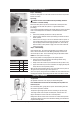
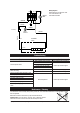
WITH 1 POLE THERMAL O/LOAD THERMOSTAT CONTROLLED N N Wiring Diagram Single Element up to 3kW with 1 Pole. T.O/L: Thermal Over Load. Thermostat Controlled BLUE L BLUE RESET T.O/L T.O.L. BROWN WHITE WHITE T. STAT. BLACK BLACK LIGHT FASCIA T.O/L ELEMENT ASSY. T.O.L. Problem Solving Symptom 85741 Possible Cause Solution Water isolating valve turned off. Check isolation valve is turned on. Blocked filter or meter tube. Blocked strainer. Contact Zip authorised agent. Jammed ball valve assembly.
Spare Parts Key Part No Description Key Part No Description 1 Cistern lid clamp kit 16 SP90504 Strap & key kit 5 & 7.5 litres 2 SP90488 Cistern lid gasket kit 17 SP90505 Tap nut kit 3 SP90490 Gasket kit 18 SP90506 Tap extension 4 SP90083 Float valve kit, with float 19 SP80563 Element kit 1.5kW 110v 1.5 & 3 litres 5 SP90069 Jumper valve kit, with seals 19 SP90485 Element kit 1.5kW 240v 1.5 & 3 litres 6 SP90102 Cistern float 19 SP90486 Element kit 2.4kW 240v 5.0 & 7.
End of life disposal The use of this crossed out wheeled bin logo indicates that this product needs to be disposed of separately to any other household waste. Within each of the European Union member countries, provisions have been made for the collection and recycling of unwanted electrical and electronic equipment. In order to preserve our environment we ask that you dispose of this product correctly. Please contact Zip Customer Service for advice on 0845 6 005 005.