
Operating instructions

Zip Hydroboil - Installation & Operating Instructions - 81447 - April 2013 v1.03 Page 6 of 12
Before you begin
Locatethepapermounting-holetemplatepackedwiththeheater.
Readtheinstallationandoperatinginstructionscompletely.
Decidewhethertoinstallwithconcealedorexposedplumbingand/or
electrical connections. Concealed connections are preferred for a superior
appearance.
Iftheheaterisusedforfillingcups,theninserttheflowrestrictorintotheoutlet
pipebeforesecuringtapassembly.
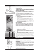
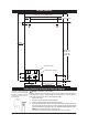
Step 1 - Positioning
Positiontheheatersothetapwilldrainontothedrainingboardordriptray.
Positionthebaseofthetaptobenotlessthan200mmabovethedraining
board.(Heightshouldbeincreasedonlyifitisessentialtoaccommodate
largervessels.)
Minimumclearancesforserviceare150mmtop,65mmleftand20mmright.
Markcornerpositiononwallsotopositionmounting-holetemplate.
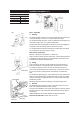
Step 2 - Fastening
Positionmounting-holetemplateonthewallanddrillmountingholeswhere
shown.
Drillholesforwaterinlet,ventoutletandwiringifitisintendedtoinstallthe
heaterwithconcealedelectricalandplumbingconnections.
Removecoverfasteningscrewsandliftcoverawayfromchassis.
Installplumbingandwiring,andpreparepipeendsforconnectionasshownin
step 3.
Screwheaterchassistothewallusingthesuppliedfixings, ensurethefixings
aresuitableforthesubstrate.Ifnotsupplyyourownsuitablefixings.
Ensurethemountingsurfaceiscapableofsupportingtheweightofthefilled
unit,fixingsmustbecapableofsupportingtheheaterweightwhenfilled.
See chart on page 7.
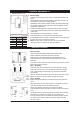
Installation Procedures
COLD
INLET
VENT
OUTLET
INLET
POSITION
VENT
POSITION
Front View
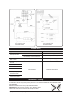
b. Electrical supply.
Astandard13ampdoublepolefusedspuronthewallwithin1500mmofthe
heater.
Isolationswitchesmusthaveacontactseparationofatleast3mminallpoles.The
circuit should be protected by a suitably rated RCD.
HS140/HS040(40ltr)shouldbeprovidedwiththeirowndedicated30Asupply.
TheelectricalinstallationshouldcomplywithcurrentIEEregulationsandany
LocalAuthorityrequirements.
c. Apotablecoldwatersupplywithaminimumworkingpressureof0.07MPa
(0.7bar)andamaximumworkingpressureof0.7MPa(7bar)connectedviaan
isolation valve.
d. Outletdrainagetoasinkdrainingboardortoadriptray.
e. Accesstodrainagefromaventsituatedatthebaseoftheheater.
f. Inallinstallationinstancesthewallsoftheheatermustbeverticalandthebase
horizontal,therecanbenoexceptionstothisrule.
g. Note: Ifthewaterpressureislikelytoexceed7bar,a3.5barpressure
reducingvalvemustbeinstalledinthecoldwatersupplyline.
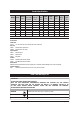
Size Kw Amps
10 Ltr 3.0kW 13 A
15 Ltr 3.0kW 13 A
25 Ltr 3.0kW 13 A
40 Ltr 6.0kW 30 A
Installation Requirements Cont.
Concealed
Services
Exposed
Services
MinimumClearanceinmm